CSI is a handful of indicators, several report formats, and a table behind every choice. The parameter count is what makes it hard rather than any single idea in it. This page collects the tables the choices come from. It then sets seventeen conformance test configurations beside them.
CSI stands for Channel State Information and it is pretty confusing concept. First, it confused me because of too many parameters for configuration and then it became even more confusing with introduction of CA (Carrier Aggregation). It would be very hard to understand every details without having some hands-on (e.g, testing or developing on your own). My recommendation is to go through the basic defintions and additional pages linked in < What is CSI > section and then go through the test procedures briefly described in this page in order to get better sense on the concept.
- What is CSI ?
- Why So Complicated
- Important Tables - Transmission Mode and Codebooks
- Important Tables - CSI RS and Periodicity
- CSI Configuration Example
- Example 1 : 36.521 9.2.1.1 FDD CQI Reporting under AWGN conditions with PUCCH 1-0
- Example 2 : 36.521 9.2.1.2 TDD CQI Reporting under AWGN conditions with PUCCH 1-0
- Example 3 : 36.521 9.2.2.1 FDD CQI Reporting under AWGN conditions with PUCCH 1-1
- Example 4 : 36.521 9.2.3.1_D FDD CQI Reporting under AWGN conditions with PUCCH 1-1 for eDL-MIMO
- Example 5 : 36.521 9.2.3.2_D TDD CQI Reporting under AWGN conditions with PUCCH 1-1 for eDL-MIMO
- Example 6 : 36.521 9.3.1.1.1 FDD CQI Reporting under fading conditions with PUSCH 3-0
- Example 7 : 36.521 9.3.1.1.2 TDD CQI Reporting under fading conditions with PUSCH 3-0
- Example 8 : 36.521 9.3.1.2.1_D FDD CQI Reporting under fading conditions with PUSCH 3-1 for eDL MIMO
- Example 9 : 36.521 9.3.1.2.2_D - TDD CQI Reporting under fading conditions with PUSCH 3-1 for eDL MIMO
- Example 10 : 36.521 9.3.4.1.1 FDD CQI Reporting under fading conditions with PUSCH 2-0
- Example 11 : 36.521 9.3.4.1.2 TDD CQI Reporting under fading conditions with PUSCH 2-0
- Example 12 : 36.521 9.3.4.2.1 FDD CQI Reporting under fading conditions with PUCCH 2-0
- Example 13 : 36.521 9.3.4.2.2 TDD CQI Reporting under fading conditions with PUCCH 2-0
- Example 14 : 36.521 9.4.1.1.1 FDD PMI Reporting with PUSCH 3-1, Single PMI
- Example 15 : 36.521 9.4.1.1.2 TDD PMI Reporting with PUSCH 3-1, Single PMI
- Example 16 : 36.521 9.4.1.2.1 FDD PMI Reporting with PUCCH 2-1, Single PMI
- Example 17 : 36.521 9.4.1.2.2 TDD PMI Reporting with PUCCH 2-1, Single PMI
- Reference
What is CSI ?
The name covers several separate reports, and a UE rarely sends all of them. Which ones travel, how often, and on which channel are three different questions. The list below names them, and the links after it take each one on its own.
CSI is a kind of collective name of several different type of indicators (UE report) as listed below.
- Channel Quality Indicator(CQI)
- precoding matrix indicator (PMI)
- precoding type indicator (PTI)
- rank indication (RI)
For the overall meaning of these CSI elements and reporting cycles and RRC elements, refer to following links. In this page, I would mostly focus on MAC/PHY layer issues.
- CQI
- CQI, PMI, RI Reporting Configuation-Details on Periodic Report
- CQI, PMI, RI Reporting Configuration - Details for Aperiodic Report
- CQI/RI Feedback type
Base framework of CSI is described in 36.213 7.2 UE procedure for reporting Channel State Information (CSI). It is around 30 pages as of Rel 11 specification, but can be one of the most complicated part of whole 36.213. By concept this is difficult and in addition most of these are very tightly related to 36.211 (L1 procedure) and 36.331 (RRC Procedure). Inter-relations amongh these multiple standards would be another factors making your head spin. So don't get disappointed if you don't understand those details when you first read this page or 3GPP documents.
36.213 clause 7.2 now names five components rather than four. Its opening sentence lists Channel Quality Indicator, precoding matrix indicator, precoding type indicator, CSI-RS resource indicator and rank indication. Says the eNB controls the time and frequency resources used to report them.
CQI answers how good the channel is : it is the only component every reporting mode on this page carries.PMI answers which precoder to use : the index it carries points into one of the codebooks in the next section.RI answers how many layers the channel will take : it is reported only in the transmission modes that can use more than one.PTI belongs to the two stage codebooks : 36.213 lists it beside CQI and PMI in the periodic reporting rules.CRI is the one the list above predates : the CSI-RS resource indicator names which CSI-RS resource a report refers to.The eNB owns the schedule : 36.213 gives it control of the time and frequency resources for every one of them.
Why So Complicated
I think the proper question for this subsection should be "Why I think it is so complicated ?". It may not be that comlicated for others.. but it is complicated to me.. very much !
- First thing that confused me is that there are many different types of CSIs and depending on which CSI is reported, UE should use different PUCCH Format. (So you need to understand the details of each PUCCH format)
- Second thing is that what kind of CSI is required is largely influenced by what kind of Transmission Mode is being applied. (So you need to know the details of Transmission Mode)
- And then we have another thing to think about. it is about DCI format. In many cases, DCI carries some special field that is requesting specific CSI report (e.g, CQI request, CSI request field) or some fields which influence CSI measurement process (e.g, Precoding Matrix info). For each transmission mode, there is one or a couple of specific DCI formats that can be applied for a specific transmission mode. So you need to understand the details of each DCI formats and how each of those DCI formats are used for each specific Transmission Mode.
- Last.. most complicated/confusing things .. there are a lot of IEs in RRC messages (e.g, RRC Connection Setup or RRC Connection Recofigurations) that defines on 'what kind of CSI a UE need to report', 'when (in what cycle) to send the report' and 'how the physical layer parameters for PUCCH format is configured'.
- Even on top of these, I got more complicated situation now with introduction of Carrier Aggregation, because you have to think of "Does UE need to report CSI for only PCC or only SCC or Both ?" "Can UE report CSI for PCC and SCC simultaneously ?" etc
Each of those four is answered somewhere on this page or on one linked from it. Taking them in the order given above turns the list of complaints into a reading order.
Which CSI and which PUCCH format : the reporting mode tables settle both. The CQI/PMI Feedback type page holds them.Which transmission mode : the codebook section below gives the bitmap width for every mode and antenna count.Which DCI format : the CSI request field travels in the uplink grant. The aperiodic report page follows it back to the RRC lists.Which RRC fields : those same fields carry real values in the seventeen configurations at the end of this page.Carrier aggregation multiplies all four : one grant can reach more than one cell. So every question above gains a per cell answer.
Important Tables - Transmission Mode and Codebooks
One of the most important purpose of CSI on UE side is to estimate the channel quality and recommend a proper precoding matrix to network. So large part of CSI estimation and report is tightly related to various precoding matrix. There are several different sets of precoding matrix and different precoding matrix set (this set is called 'Codebook') is used for different transmission condition (more specifically different transmission mode). Therefore, in order to understand the overal mechanism of CSI estimation/report, the first step would be to get familiar with all of these precoding matrix set and how to represent each specific matrix from the selected set.
The purpose of this sub section is to put all the possible sets of precoding matrix together for easy future reference and give you overall understanding.
Since there are a lot of different sets of matrix and it is impossible to notify the values of matrix itself, there should be some other efficient way to indicate each matrix. The way to be used in LTE is to assign a number (index) to each of the precoding matrix and use that index number to communicate between network and UE about the specific precoding matrix.
First table I want to introduce you is the table shown below. It shows the how many bits that can be used for each of the transmission mode and number of transmission antenna. This number of bits reprented here indicate (imply) how many different precoding matrix can be used for each cases. For example, if you see 'Transmission Mode 3' and '2 antenna ports' case, you see the number '2'. It means that there is total two matrix that can be used as precoding matrix. As an other example, if you see 'Transmission Mode 4' and '4 antenna ports' case, you see the number '64'. It means that there is total 64 matrix that can be used as precoding matrix.
Actually the explicit meaning of this table is to indicate 'how many bits are used to indicate each precoding matrix'. It is represented as binary number, but the index number in decimal is not as you learn in math course. This number is a 'bit mapped' number in which the position in the bit string represent a decimal index number. For example, if you look into 'Transmission Mode 4' and '2 Antenna ports', you would see 6. It means a binary number with 6 bit number is used to indicate each index of 6 different precoding matrix.
000001 --> index number 0
000010 --> index number 1
000100 --> index number 2
001000 --> index number 3
010000 --> index number 4
100000 --> index number 5
36.213 Table 7.2-1b: Number of bits in codebook subset restriction bitmap for applicable transmission modes
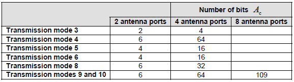
The table gives one number per transmission mode and antenna count. That number is the width of the bitmap. The width is what limits how many precoders a mode can choose between.
Two antenna ports never need more than 6 bits : transmission modes 4, 8, 9 and 10 take 6, and modes 5 and 6 take 4.Transmission mode 3 takes the fewest : 2 bits at two antenna ports and 4 bits at four.Four antenna ports raise the count sharply : 64 bits for modes 4, 9 and 10, and 16 for modes 5 and 6.Only modes 9 and 10 reach eight antenna ports : the bitmap there is 109 bits. No other row has an entry in that column.The blank cells are not zeros : they mark combinations the table does not define at all.
The numbers shown in the above table (36.213 Table 7.2-1b) shows only the index precoding matrix that can be used and it does not let you know exactly which sets of precoding matrix. For the specific precoding matrix sets (we call this set as Codebook), you need to refer to other tables.
The first set of precoding matrix (CodeBook) is shown in the following table. This set is used in the case where Tx antenna ports {0,1} and CSI antenna port {15, 16} is used. Each of these antenna ports is using corresponding reference signal 0,1 and 15,16 introduced in downlink reference signal page
36.211 Table 6.3.4.2.3-1: Codebook for transmission on antenna ports {0,1} and for CSI reporting based on antenna ports {0,1} or {15,16}
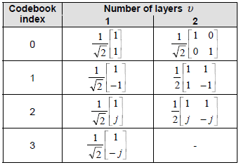
This is the shortest codebook on the page. Four indices cover one layer and three cover two, which is the whole choice a two port transmitter has.
The column heading is the number of layers : the spec writes it as a Greek upsilon. The page writes it as v in the text beside the tables.Every one layer entry is a two element vector : the four of them are 1 over root 2 times 1 with 1, -1, j and -j.The two layer entries are matrices : index 0 is the identity over root 2. Indices 1 and 2 are half times a two by two.Index 3 has no two layer entry : the cell carries a dash. That is why the two layer choice is three wide and not four.Six bits cover seven entries : 36.213 Table 7.2-1c gives a0 to a3 to the one layer column and a4 and a5 to two of the three two layer entries.One entry has no bit at all : the two layer precoder at codebook index 0 carries a dash in that table, so a restriction bitmap cannot exclude it.
The index of each matrix in this codebook is represented by the location of 6 bit binary number as indicated as below. The order of the 6 bit number is a5 a4 a3 a2 a1 a0. For example, if you set 0 1 0 0 0 0, it means the index 4. If you compare 36.213 Table 7.2-1c and 36.211 Table 6.3.4.2.3-1. You will now the matrix indicated by 010000 is as follows (the matrix marked in yellow cell).
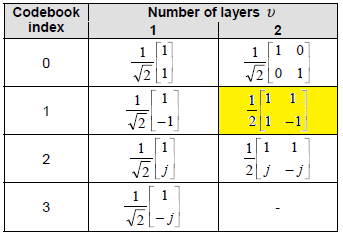
The same codebook again, with one cell filled in yellow. The highlight is the author's, and it marks the entry the bit position above it selects.
36.213 Table 7.2-1c: Association of bits in codebookSubSetRestriction bitmap to precoders in the 2 antenna port codebook of Table 6.3.4.2.3-1 in 36.211
|
Codebook index i_c |
number of layers |
|
|
1 |
2 |
|
|
0 |
a0 |
- |
|
1 |
a1 |
a4 |
|
2 |
a2 |
a5 |
|
3 |
a3 |
- |
Following table shows a more complicated type of matrix set (Codebook) for the case where you use transmission antenna ports {0,1,2,3} or CSI reference antenna ports {15,16,17,18}. It can represent total 64 different matrix. Just from the table, it would not be easy to know each element values of a matrix. To figure out each matrix element value, you need to go through a couple of additional steps shown in "Codebook selection for Precoding - 4 Antenna Ports" section in precoding page.
36.211 Table 6.3.4.2.3-2: Codebook for transmission on antenna ports {0,1,2,3} and for CSI reporting based on antenna ports {0,1,2,3} or {15,16,17,18}

The four port codebook is the one that needs 64 bits. Sixteen indices each carry a vector and four precoders, one per layer count.
Sixteen rows and four layer columns give 64 entries : that is exactly the bit count the table further up gives for four antenna ports.Each row starts from one vector : un is written out in the second column. Every precoder in the row is built from it.The superscripts name which columns are taken : W0(14) uses columns 1 and 4, and W0(124) uses 1, 2 and 4.The scaling follows the layer count : divided by root 2 for two layers, root 3 for three and 2 for four.The vectors are not all the same shape : indices 4 to 7 carry entries built from 1 plus or minus j over root 2. The rest carry 1, -1, j and -j.
Each of the matrix index of the 64 different matrix shown in above table is represented in the location in 64 bitmap binary number as shown below.
Association of bits in codebookSubSetRestriction bitmap to precoders in the 4 antenna port codebook of Table 6.3.4.2.3-2 in 36.211
|
Codebook index i_c |
number of layers |
|||
|
1 |
2 |
3 |
4 |
|
|
0 |
a0 |
a16 |
a32 |
a48 |
|
1 |
a1 |
a17 |
a33 |
a49 |
|
2 |
a2 |
a18 |
a34 |
a50 |
|
3 |
a3 |
a19 |
a35 |
a51 |
|
4 |
a4 |
a20 |
a36 |
a52 |
|
5 |
a5 |
a21 |
a37 |
a53 |
|
6 |
a6 |
a22 |
a38 |
a54 |
|
7 |
a7 |
a23 |
a39 |
a55 |
|
8 |
a8 |
a24 |
a40 |
a56 |
|
9 |
a9 |
a25 |
a41 |
a57 |
|
10 |
a10 |
a26 |
a42 |
a58 |
|
11 |
a11 |
a27 |
a43 |
a59 |
|
12 |
a12 |
a28 |
a44 |
a60 |
|
13 |
a13 |
a29 |
a45 |
a61 |
|
14 |
a14 |
a30 |
a46 |
a62 |
|
15 |
a15 |
a31 |
a47 |
a63 |
Now, we have to figure out which specific bits indicated in 36.213 Table 7.2-1b maps to one specific matrix in 36.211 Table 6.3.4.2.3-1,36.211 Table 6.3.4.2.3-2 or 36.213Table 7.2.4-1, 7.2.4-2, 7.2.4-3, 7.2.4-4, 7.2.4-5, 7.2.4-6, 7.2.4-7, or 7.2.4-8. These mapping is described in 36.213 section 7.2 as shown below. Some of the mapping is obvious, but some of mapping is still confusing to me. When the all matrix in a code book is used for example Transmission Mode 4,6,8 the mapping looks obvious, but when only some of the matrices in the code book(e.g, Transmission Mode 3) is used, the mapping looks confusing.
Most complicated and confusing mapping is for TM9.. and I still need more study to clearly describe this mapping.
Transmission mode 3
a. 2 antenna ports: bit a_(v-1), v = 2 is associated with the precoder in Table 6.3.4.2.3-1 of 36.211 corresponding to v layers and codebook index 0 while bit a_0 is associated with the precoder for 2 antenna ports in clause 6.3.4.3 of 36.211.
b. 4 antenna ports: bit a_(v-1), v = 2,3,4 is associated with the precoders in Table 6.3.4.2.3-2 of 36.211 corresponding to v layers and codebook indices 12, 13, 14, and 15 while bit 0 a is associated with the precoder for 4 antenna ports in clause 6.3.4.3 of 36.211.
Transmission mode 4
Mode 4 is the first one whose bitmap has to cover more than one layer count. At two antenna ports the mapping is a table of its own, and at four it becomes an arithmetic rule.
a. 2 antenna ports: see Table 7.2-1c
b. 4 antenna ports: bit a_16(v-1)+i_c is associated with the precoder for v layers and with codebook index i_c in Table 6.3.4.2.3-2 of 36.211
Transmission mode 5 and 6
a. 2 antenna ports: bit a_ic is associated with the precoder for v = 1 layer with codebook index i_c in Table 6.3.4.2.3-1 of 36.211
b. 4 antenna ports: bit a_ic is associated with the precoder for v = 1 layer with codebook index i_c in Table 6.3.4.2.3-2 of 36.211
Transmission mode 8
Mode 8 uses the same two rules as mode 4, with one limit added. Its layer count stops at two, which is why the four port bitmap is half the width that mode 4 needs.
a. 2 antenna ports: see Table 7.2-1c
b. 4 antenna ports: bit a_16(v-1)+i_c is associated with the precoder for v layers and with codebook index i_c in Table 6.3.4.2.3-2 of 36.211, v = 1,2
Transmission mode 9 and 10
These two are the only modes with an eight antenna port rule, and that rule is why their bitmap runs to 109 bits. The layer count reaches eight, and a function rather than a multiplier places each bit.
a. 2 antenna ports: see Table 7.2-1c
b. 4 antenna ports: bit a_16(v-1)+i_c associated with the precoder for v layers and with codebook index ic in Table 6.3.4.2.3-2 of 36.211.
c. 8 antenna ports: bit a_f1(v-1)+i_c is associated with the precoder for v layers (v ∈{1,2,3,4,5,6,7,8}) and codebook index ic1 where f 1(⋅) = {0,16,32,36,40,44,48,52 } and bit a_(53+g1(v-1)+i_c2) is associated with the precoder for v layers (v ∈{1,2,3,4} ) and codebook index ic2 where g1(⋅) = {0,16,32,48 }. Codebook indices ic1 and ic2 are given in Table 7.2.4-1, 7.2.4-2, 7.2.4-3, 7.2.4-4, 7.2.4-5, 7.2.4-6, 7.2.4-7, or 7.2.4-8, for v =1,2,3,4,5,6,7, or 8 respectively.
Important Tables - CSI RS and Periodicity
A CSI-RS is only useful if the UE knows where to look for it. Two tables settle that, and one RRC field points into each. The first fixes the position inside a resource block, and the second fixes which subframes carry it.
< 36.211 Table 6.10.5.2-1: Mapping from CSI reference signal configuration to (k', l' ) for normal cyclic prefix. >
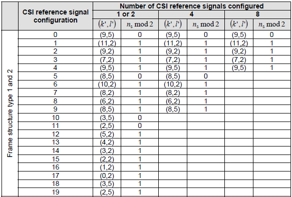

The configuration number on the left is a position, not a count. Reading across gives the subcarrier and symbol the CSI-RS sits on, and which half of the frame it falls in.
The pair in each cell is k' and l' : a subcarrier offset and a symbol offset inside the resource block.The column beside it is ns mod 2 : 0 puts the resource in the even slot and 1 in the odd one.The three column groups are antenna counts : 1 or 2, 4, and 8 configured CSI reference signals.More antenna ports means fewer configurations : 1 or 2 ports reach configuration 19, four ports reach 9, and eight ports reach 4.Configurations 20 to 31 are TDD only : the left margin of the second part reads frame structure type 2 only.That is why the RRC range runs to 31 : resourceConfig-r10 is an INTEGER from 0 to 31. The table has exactly that many rows.
< 36.211 Table 6.10.5.3-1: CSI reference signal subframe configuration. >
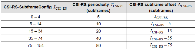
This table is the timing half, and it is short enough to memorise. One index carries both the period and the offset, which is the same trick the CQI reporting index uses.
Five bands cover the whole range : 0 to 4, 5 to 14, 15 to 34, 35 to 74 and 75 to 154.Each band is one periodicity : 5, 10, 20, 40 and 80 subframes in that order.The offset is the index less the first value of its band : ICSI-RS minus 5, minus 15, minus 35 and minus 75.The band width is the periodicity : the 5 to 14 band holds ten indices and gives a period of 10. So the offset covers every subframe of the cycle.Index 154 is the last one defined : it gives a period of 80 and an offset of 79, which is why the RRC range stops there.A worked example reads off in one step : subframeConfig-r10 of 20 falls in the 15 to 34 band. So the period is 20 subframes and the offset is 5.

The picture below is the RRC field itself rather than a specification table. It is worth reading beside the two tables above, because each of its integer ranges is the height of one of them.
resourceConfig-r10 runs from 0 to 31 : that is the row count of the configuration table further up.subframeConfig-r10 runs from 0 to 154 : that is the last index of the periodicity table.antennaPortsCount-r10 has four values : an1, an2, an4 and an8. That is why the configuration table has three column groups and not more.p-C-r10 is a power offset : an INTEGER from -8 to 15. It is the only field here that is not a table index.The zero power branch repeats the timing field : it carries its own subframe config alongside a 16 bit resource list.One part of this screenshot has moved since : 36.331 v19.3.0 types the zero power branch as ZeroTxPowerCSI-RS-Conf-r12 rather than spelling the CHOICE out in place.The fields inside it are unchanged : the same 16 bit list and the same 0 to 154 subframe config, with an -r12 suffix instead of -r10.
CSI Configuration Example
Even though you think you understood all the details of each items convered here, you are not sure if you understand what's going on when all those items are put together and interworking each other. As in other case, the best way is Practice, Practice, Practice. If you have chance to create a test case for the CSI operation, you will have pretty deep/clear knowledge. If not, at least try to get some protocol log for CSI report and look into it. If you don't have chance to create the test case nor you don't have access to protocol log, a good alternative is to look into conformance test condition and imagine what would happen at each subframe according to the condition set in each test case.
I would write down RRC message part of CSI related conformance test case and see how much you understand these RRC settings based on what you learned in this page (including all related pages hyperlinked from this page).
The seventeen clause numbers were checked against 36.521-1 v19.2.0. All of them still exist. Every title still matches, except that the specification uses a dash where this page uses the word with.
The blocks are transcriptions, not captures : each one is the RRC configuration a test case prescribes, with the author's own comments beside the values.None of the values has been changed : a test configuration is only meaningful as the test wrote it.The DEFAULT suffix is not an RRC field name : it marks the default version of an information element that a conformance test starts from.Read cqi-pmi-ConfigIndex first in each one : the author's comment beside it already gives the period and the offset it decodes to.The examples divide into three groups : clause 9.2 for CQI under AWGN, clause 9.3 for CQI under fading, and clause 9.4 for PMI.FDD and TDD come in pairs : almost every clause number has a sibling that differs only in the duplex mode.
Example 1 : 36.521 9.2.1.1 FDD CQI Reporting under AWGN conditions with PUCCH 1-0
The simplest configuration on the page. One information element carries the whole of it. Aperiodic reporting is absent and no RI is configured, so what is left is a wideband CQI on a fixed period.
Condition : PDSCH via DCI Format 1A
RRC Configuration :
RRC configuration for
CQI-ReportConfig-DEFAULT ::= SEQUENCE {
    cqi-ReportModeAperiodic            Not present  // No Aperiodic CQI
    nomPDSCH-RS-EPRE-Offset        0
    cqi-ReportPeriodic CHOICE {
    setup SEQUENCE {
        cqi-PUCCH-ResourceIndex      0
        cqi-pmi-ConfigIndex              6     // Period = 5, Offset = 4
        cqi-FormatIndicatorPeriodic CHOICE {
            widebandCQI NULL                  // Wideband CQI
        }
    ri-ConfigIndex                          NULL       // NO RI
    simultaneousAckNackAndCQI      FALSE
    }
    }
}
Example 2 : 36.521 9.2.1.2 TDD CQI Reporting under AWGN conditions with PUCCH 1-0
The same test in TDD, and the difference is one extra block. TDD-Config-DEFAULT sets the uplink downlink pattern, and the reporting index changes with it because TDD reads its own table.
Condition :
i) PDSCH via DCI Format 1A
ii) Physical channel for CQI reporting : PUCCH Format 2
RRC Configuration :
RRC configuration for
TDD-Config-DEFAULT ::= SEQUENCE {
    subframeAssignment                 sa2         //DSUDDDSUDD
    specialSubframePatterns           ssp4
}

CQI-ReportConfig-DEFAULT ::= SEQUENCE {
    cqi-ReportModeAperiodic            Not present    // No Aperiodic CQI
    nomPDSCH-RS-EPRE-Offset        0
    cqi-ReportPeriodic CHOICE {
    setup SEQUENCE {
        cqi-PUCCH-ResourceIndex      0
        cqi-pmi-ConfigIndex              3    // Period = 5, Offset = 2
        cqi-FormatIndicatorPeriodic CHOICE {
            widebandCQI NULL
        }
    ri-ConfigIndex                           NULL
    simultaneousAckNackAndCQI       FALSE
    }
    }
}
Example 3 : 36.521 9.2.2.1 FDD CQI Reporting under AWGN conditions with PUCCH 1-1
PUCCH 1-1 adds a PMI, so this configuration has to say which precoders are allowed. Transmission mode 4 appears here for the first time, and a six bit codebook subset restriction comes with it. RI is configured as well.
Condition :
i) PDSCH via DCI Format 2
ii) Physical channel for CQI reporting : PUCCH Format 2
iii) It is intended to have UL collisions between RI reports and HARQ-ACK, since the RI reports shall not be used by the eNB in this test.
RRC Configuration :
RRC configuration for
PhysicalConfigDedicated-DEFAULT ::=
SEQUENCE {
    cqi-ReportConfig CQI-ReportConfig-DEFAULT
    antennaInfo CHOICE {
    antennaInfoDedicated ::= SEQUENCE {
        transmissionMode               tm4
    }
    codebookSubsetRestriction CHOICE {
        n2TxAntenna-tm4               010000
    ue-TransmitAntennaSelection CHOICE {
        release                              NULL
    }
    }
}

PDSCH-ConfigDedicated-DEFAULT ::=
SEQUENCE {
     p-a dB-3
}

CQI-ReportConfig-DEFAULT ::= SEQUENCE {
    cqi-ReportModeAperiodic            Not present     // No Aperiodic CQI
    nomPDSCH-RS-EPRE-Offset        0
    cqi-ReportPeriodic CHOICE {
    setup SEQUENCE {
        cqi-PUCCH-ResourceIndex      0
        cqi-pmi-ConfigIndex              6                // Period = 5, Offset = 4
        cqi-FormatIndicatorPeriodic CHOICE {
            widebandCQI NULL
        }
    ri-ConfigIndex                          1               // Same Period as CQI, 1 subframe before CQI
    simultaneousAckNackAndCQI FALSE
    }
    }
}
Example 4 : 36.521 9.2.3.1_D FDD CQI Reporting under AWGN conditions with PUCCH 1-1 for eDL-MIMO
The first eight block configuration on the page. Transmission mode 9 brings a CSI-RS of its own, so a 64 bit codebook restriction replaces the six bit one and four CSI-RS antenna ports are configured.
Condition :
i) PDSCH via DCI Format 2C
ii) Physical channel for CQI/PMI reporting : PUSCH
iii) Physical channel for RI reporting : PUCCH
iv) To avoid collisions between CQI/PMI reports and HARQ-ACK it is necessary to report both on PUSCH instead of PUCCH. PDCCH DCI format 0 shall be transmitted in downlink SF#1 and #6 to allow periodic CQI/PMI to multiplex with the HARQ-ACK on PUSCH in uplink SF#0 and #5.
v) CSI reference signals = Antenna ports 15,?18
RRC Configuration :
RRC configuration for
RadioResourceConfigDedicated-SRB2-DRB(n, m) ::=
SEQUENCE {
    physicalConfigDedicated     CQI-ReportConfig-r10-DEFAULT usingcondition RBC
    antennaInfo CHOICE {
        explicitValue             AntennaInfoDedicated
    }
}

PDSCH-ConfigDedicated-DEFAULT ::=
SEQUENCE {
     p-a           dB0
}

AntennaInfoDedicated-r10 ::= SEQUENCE {
    transmissionMode-r10                tm9-v1020
    codebookSubsetRestriction-r10   0x0000 0000 0100 0000     // 64 bits since this is for TM9 / 4 Antenna
    }
    ue-TransmitAntennaSelection CHOICE {
        release         NULL
}

CQI-ReportConfig-r10 ::= SEQUENCE {
    cqi-ReportModeAperiodic-r10     Not Present      // No Aperiodic CQI
    nomPDSCH-RS-EPRE-Offset       0
    cqi-ReportPeriodic-r10              CQI-ReportPeriodic-r10-DEFAULT
}

CQI-ReportPeriodic-r10 ::= CHOICE {
    setup SEQUENCE {
        cqi-PUCCH-ResourceIndex-r10            0
        cqi-PUCCH-ResourceIndexP1-r10         Not present
        cqi-pmi-ConfigIndex                          2  // Period = 5, Offset = 0
        cqi-FormatIndicatorPeriodic-r10 CHOICE {
            widebandCQI-r10 SEQUENCE {
                csi-ReportMode-r10                  Not present
        }
        ri-ConfigIndex                                 1   // Same Period as CQI, 1 subframe before CQI
        simultaneousAckNackAndCQI              FALSE
    }
    }
}

CSI-RS-Config-r10 ::= SEQUENCE {
    csi-RS-r10 CHOICE{
        release NULL
        setup SEQUENCE {
            antennaPortsCount-r10                 an4
            resourceConfig-r10                       0
            subframeConfig-r10                      1
            p-C-r10                                    -3
        }+
    }
}
Example 5 : 36.521 9.2.3.2_D TDD CQI Reporting under AWGN conditions with PUCCH 1-1 for eDL-MIMO
The TDD twin of the case above, and the longest block list in the group. Eight CSI-RS antenna ports replace four. The RI index jumps to 805, because the rank is reported far less often than the CQI.
Condition :
i) PDSCH via DCI Format 2C
ii) Physical channel for CQI/PMI reporting : PUSCH
iii) Physical channel for RI reporting : PUSCH
iv) To avoid collisions between CQI/PMI reports and HARQ-ACK it is necessary to report both on PUSCH instead of PUCCH. PDCCH DCI format 0 shall be transmitted in downlink SF#3 and #8 to allow periodic CQI/PMI to multiplex with the HARQ-ACK on PUSCH in uplink SF#7 and #2.
v) RI reporting interval is set to the maximum allowable length of 160ms to minimise collisions between RI, CQI/PMI and HARQ-ACK reports. In the case when all three reports collide, it is expected that CQI/PMI reports will be dropped, while RI and HARQ-ACK will be multiplexed. At eNB, CQI report collection shall be skipped every 160ms during performance verification.
v) CSI reference signals = Antenna ports 15,?18
RRC Configuration :
RRC configuration for
RadioResourceConfigDedicated-SRB2-DRB(n, m) ::=
SEQUENCE {
    physicalConfigDedicated     CQI-ReportConfig-r10-DEFAULT usingcondition RBC
    antennaInfo CHOICE {
        explicitValue             AntennaInfoDedicated
    }
}

PDSCH-ConfigDedicated-DEFAULT ::=
SEQUENCE {
     p-a           dB0
}

AntennaInfoDedicated-r10 ::= SEQUENCE {
    transmissionMode-r10                tm9-v1020
    codebookSubsetRestriction-r10   0x0000 0000 0020 0000 0000 0001 0000
    }
    ue-TransmitAntennaSelection CHOICE {
        release         NULL
}

CQI-ReportConfig-r10 ::= SEQUENCE {
    cqi-ReportModeAperiodic-r10     Not Present             // No Aperiodic CQI
    nomPDSCH-RS-EPRE-Offset       0
    cqi-ReportPeriodic-r10              CQI-ReportPeriodic-r10-DEFAULT
}

CQI-ReportPeriodic-r10 ::= CHOICE {
    setup SEQUENCE {
        cqi-PUCCH-ResourceIndex-r10            0
        cqi-PUCCH-ResourceIndexP1-r10         Not present
        cqi-pmi-ConfigIndex                          3           // Period = 5, Offset = 2
        cqi-FormatIndicatorPeriodic-r10 CHOICE {
            widebandCQI-r10 SEQUENCE {
                csi-ReportMode-r10                  Not present
        }
        ri-ConfigIndex                                 805      // Period = 32 x CQI Period, Offset = Same as CQI
        simultaneousAckNackAndCQI              FALSE
    }
    }
}

TDD-Config-DEFAULT ::= SEQUENCE {
    subframeAssignment                           sa2
    specialSubframePatterns                     ssp4
}

PUCCH-ConfigDedicated-DEFAULT ::= SEQUENCE
{
    ackNackRepetition CHOICE {
        release                                       NULL
    }
    tddAckNackFeedbackMode                 Multiplexing
}

CSI-RS-Config-r10 ::= SEQUENCE {
    csi-RS-r10 CHOICE{
        release NULL
        setup SEQUENCE {
            antennaPortsCount-r10                 an8
            resourceConfig-r10                       0
            subframeConfig-r10                      3
            p-C-r10                                    -6
        }
    }
}
Example 6 : 36.521 9.3.1.1.1 FDD CQI Reporting under fading conditions with PUSCH 3-0
Fading conditions and a PUSCH mode, so the periodic settings disappear entirely. One field carries the whole configuration, and rm30 is what makes the report aperiodic.
Condition :
i) PDSCH via DCI Format 1A
ii) Physical channel for CQI/PMI reporting : PUSCH
UL transmission every 5 ms to carry the PUSCH CQI feedback via PDCCH DCI format 0 with CQI request bit set to 1 and I_MCS=29 and N_PRB allocated to be less or equal to 4
RRC Configuration :
RRC configuration for
CQI-ReportConfig-DEFAULT ::= SEQUENCE {
    cqi-ReportModeAperiodic            rm30
    nomPDSCH-RS-EPRE-Offset        0
    cqi-ReportPeriodic                     Not Present
}
Example 7 : 36.521 9.3.1.1.2 TDD CQI Reporting under fading conditions with PUSCH 3-0
The same single field in TDD, with the uplink downlink pattern added beside it. Nothing about the reporting mode itself changes, which is the point of running the pair.
Condition :
i) PDSCH via DCI Format 1A
ii) Physical channel for CQI/PMI reporting : PUSCH
UL transmission in subframe #2 and #7 to carry the PUSCH CQI feedback via PDCCH DCI format 0 with CQI request bit set to 1 and I_MCS=29 and N_PRB allocated to be less or equal to 4
RRC Configuration :
RRC configuration for
CQI-ReportConfig-DEFAULT ::= SEQUENCE {
    cqi-ReportModeAperiodic            rm30
    nomPDSCH-RS-EPRE-Offset        0
    cqi-ReportPeriodic                     Not Present
}
TDD-Config-DEFAULT ::= SEQUENCE {
    subframeAssignment                 sa2         //DSUDDDSUDD
    specialSubframePatterns           ssp4
}
Example 8 : 36.521 9.3.1.2.1_D FDD CQI Reporting under fading conditions with PUSCH 3-1 for eDL MIMO
Mode 3-1 carries a single PMI, so the codebook restriction returns. Two CSI-RS antenna ports are configured here, and the author's comments on the last two fields say what each of them is for.
Condition :
i) PDSCH via DCI Format 2C
ii) Physical channel for CQI/PMI reporting : PUSCH
UL transmission in subframe #0 and #5 to carry the PUSCH CQI feedback via PDCCH DCI format 0 with CQI request bit set to 1 and I_MCS=29 and N_PRB allocated to be less or equal to 4
RRC Configuration :
RRC configuration for
RadioResourceConfigDedicated-SRB2-DRB(n, m) ::=
SEQUENCE {
    physicalConfigDedicated     CQI-ReportConfig-r10-DEFAULT
    antennaInfo CHOICE {
        explicitValue             AntennaInfoDedicated
    }
}

PDSCH-ConfigDedicated-DEFAULT ::=
SEQUENCE {
     p-a           dB0
}

AntennaInfoDedicated-r10 ::= SEQUENCE {
    transmissionMode-r10                tm9-v1020
    codebookSubsetRestriction-r10   0x0000 0000 0000 0001
    }
    ue-TransmitAntennaSelection CHOICE {
        release         NULL
}

CQI-ReportConfig-r10 ::= SEQUENCE {
    cqi-ReportModeAperiodic-r10     rm31
    nomPDSCH-RS-EPRE-Offset       0
    cqi-ReportPeriodic-r10              Not Present
}

CSI-RS-Config-r10 ::= SEQUENCE {
    csi-RS-r10 CHOICE{
        release NULL
        setup SEQUENCE {
            antennaPortsCount-r10                 an2
            resourceConfig-r10                       4
            subframeConfig-r10                      1    // Delta_CSI_RS = I_CSI_RS
            p-C-r10                                     0    // the assumed ratio of PDSCH EPRE to CSI-RS EPRE
                                                                 // when UE derives CSI feedback
        }+
    }
}
Example 9 : 36.521 9.3.1.2.2_D - TDD CQI Reporting under fading conditions with PUSCH 3-1 for eDL MIMO
The TDD twin again. Only the CSI-RS subframe configuration moves, from 1 to 3, and the extra TDD and PUCCH blocks arrive with the duplex change.
Condition :
i) PDSCH via DCI Format 2C
ii) Physical channel for CQI/PMI reporting : PUSCH
UL transmission in subframe #2 and #7 to carry the PUSCH CQI feedback via PDCCH DCI format 0 with CQI request bit set to 1 and I_MCS=29 and N_PRB allocated to be less or equal to 4
RRC Configuration :
RRC configuration for
RadioResourceConfigDedicated-SRB2-DRB(n, m) ::=
SEQUENCE {
    physicalConfigDedicated     CQI-ReportConfig-r10-DEFAULT
    antennaInfo CHOICE {
        explicitValue             AntennaInfoDedicated
    }
}

PDSCH-ConfigDedicated-DEFAULT ::=
SEQUENCE {
     p-a           dB0
}

AntennaInfoDedicated-r10 ::= SEQUENCE {
    transmissionMode-r10                tm9-v1020
    codebookSubsetRestriction-r10   0x0000 0000 0000 0001
    }
    ue-TransmitAntennaSelection CHOICE {
        release         NULL
}

CQI-ReportConfig-r10 ::= SEQUENCE {
    cqi-ReportModeAperiodic-r10     rm31
    nomPDSCH-RS-EPRE-Offset       0
    cqi-ReportPeriodic-r10              Not Present
}

CSI-RS-Config-r10 ::= SEQUENCE {
    csi-RS-r10 CHOICE{
        release NULL
        setup SEQUENCE {
            antennaPortsCount-r10                 an2
            resourceConfig-r10                       4
            subframeConfig-r10                      3    // Delta_CSI_RS = I_CSI_RS
            p-C-r10                                     0    // the assumed ratio of PDSCH EPRE to CSI-RS EPRE
                                                                 // when UE derives CSI feedback
        }
    }
}

TDD-Config-DEFAULT ::= SEQUENCE {
    subframeAssignment                 sa2         //DSUDDDSUDD
    specialSubframePatterns           ssp4
}

PUCCH-ConfigDedicated-DEFAULT ::= SEQUENCE
{
    ackNackRepetition CHOICE {
        release                                       NULL
    }
    tddAckNackFeedbackMode                 Multiplexing
}
Example 10 : 36.521 9.3.4.1.1 FDD CQI Reporting under fading conditions with PUSCH 2-0
Mode 2-0 is the UE selected subband case without a PMI. The configuration is one field again, which shows how much of the work the mode number does on its own.
Condition :
i) PDSCH via DCI Format 1A
ii) Physical channel for CQI/PMI reporting : PUSCH
UL transmission every 5 ms to carry the PUSCH CQI feedback via PDCCH DCI format 0 with CQI request bit set to 1 and I_MCS=29 and N_PRB allocated to be less or equal to 4
RRC Configuration :
RRC configuration for
CQI-ReportConfig-DEFAULT ::= SEQUENCE {
    cqi-ReportModeAperiodic            rm20
    nomPDSCH-RS-EPRE-Offset        0
    cqi-ReportPeriodic                     Not Present
}
Example 11 : 36.521 9.3.4.1.2 TDD CQI Reporting under fading conditions with PUSCH 2-0
The TDD twin of the one above, and the only addition is the uplink downlink pattern. A pair like this is the quickest way to see what a duplex mode costs in configuration.
Condition :
i) PDSCH via DCI Format 1A
ii) Physical channel for CQI/PMI reporting : PUSCH
UL transmission at subframe #2 and #7 to carry the PUSCH CQI feedback via PDCCH DCI format 0 with CQI request bit set to 1 and I_MCS=29 and N_PRB allocated to be less or equal to 4
RRC Configuration :
RRC configuration for
CQI-ReportConfig-DEFAULT ::= SEQUENCE {
    cqi-ReportModeAperiodic            rm20
    nomPDSCH-RS-EPRE-Offset        0
    cqi-ReportPeriodic                     Not Present
}

TDD-Config-DEFAULT ::= SEQUENCE {
    subframeAssignment                 sa2         //DSUDDDSUDD
    specialSubframePatterns           ssp4
}
Example 12 : 36.521 9.3.4.2.1 FDD CQI Reporting under fading conditions with PUCCH 2-0
The first subband report on PUCCH. The field cqi-FormatIndicatorPeriodic takes its subband arm rather than the wideband one, and k is 1. An RI index appears beside it for the first time in this group.
Condition :
i) PDSCH via DCI Format 1A
ii) Physical channel for CQI/PMI reporting : PUSCH
UL transmission in subframe #1, #3, #5 and subframe #7 to carry the PUSCH CQI feedback via PDCCH DCI format 0 with CQI request bit set to 0. The UE will send ACK/NACK and periodic CQI report using PUSCH. In this process the SS collects wideband CQI reports and also cases where UE transmits nothing in its wideband CQI timing are counted as wideband CQI reports.
RRC Configuration :
RRC configuration for
CQI-ReportConfig-DEFAULT ::= SEQUENCE {
cqi-ReportModeAperiodic                        Not present
nomPDSCH-RS-EPRE-Offset                    0
cqi-ReportPeriodic CHOICE {
setup SEQUENCE {
cqi-PUCCH-ResourceIndex      0
cqi-pmi-ConfigIndex              1
cqi-FormatIndicatorPeriodic CHOICE {
subbandCQI                 1
}
ri-ConfigIndex                                      483
simultaneousAckNackAndCQI                  FALSE
}
  }
}
Example 13 : 36.521 9.3.4.2.2 TDD CQI Reporting under fading conditions with PUCCH 2-0
The TDD twin, and two values move rather than one. The reporting index goes from 1 to 3 and the RI index from 483 to 484, both because TDD reads its own table.
Condition :
i) PDSCH via DCI Format 1A
ii) Physical channel for CQI/PMI reporting : PUSCH
UL transmission in subframe #2 and #7 to carry the PUSCH CQI feedback via PDCCH DCI format 0 with CQI request bit set to 0. The UE will send ACK/NACK and periodic CQI report using PUSCH. In this process the SS collects wideband CQI reports and also cases where UE transmits nothing in its wideband CQI timing are counted as wideband CQI reports.
RRC Configuration :
RRC configuration for
CQI-ReportConfig-DEFAULT ::= SEQUENCE {
cqi-ReportModeAperiodic                        Not present
nomPDSCH-RS-EPRE-Offset                    0
cqi-ReportPeriodic CHOICE {
setup SEQUENCE {
cqi-PUCCH-ResourceIndex      0
cqi-pmi-ConfigIndex              3
cqi-FormatIndicatorPeriodic CHOICE {
subbandCQI                 1
}
ri-ConfigIndex                                      484
simultaneousAckNackAndCQI                  FALSE
}
  }
}

TDD-Config-DEFAULT ::= SEQUENCE {
    subframeAssignment                 sa2         //DSUDDDSUDD
    specialSubframePatterns           ssp4
}
Example 14 : 36.521 9.4.1.1.1 FDD PMI Reporting with PUSCH 3-1, Single PMI
The PMI tests start here, and the transmission mode changes to 6. Its codebook restriction is four bits wide and every one of them is set, so the UE may choose any precoder in the two port codebook.
Condition :
i) PDSCH via DCI Format 1B with randomly selected precoding matrix from codebook (Table 6.3.4.2.3-1 in TS 36.211)
ii) Physical channel for CQI/PMI reporting : PUSCH
SS schedules the UL transmission to carry the PUSCH CQI feedback via PDCCH DCI format 0 with CQI request bit set to 1 and I_MCS=29 and N_PRB allocated to be less or equal to 4.
RRC Configuration :
RRC configuration for
PhysicalConfigDedicated-DEFAULT ::= SEQUENCE {
cqi-ReportConfig CQI-ReportConfig-DEFAULT
antennaInfo CHOICE {
explicitValue                            AntennaInfoDedicated
}
}

AntennaInfoDedicated ::= SEQUENCE {
transmissionMode                                    tm6
codebookSubsetRestriction CHOICE{
n2TxAntenna-tm6                           1111
}
ue-TransmitAntennaSelection CHOICE{
release                                          NULL
}

CQI-ReportConfig-DEFAULT ::= SEQUENCE {
cqi-ReportModeAperiodic                           rm31
nomPDSCH-RS-EPRE-Offset                       0
cqi-ReportPeriodic                                    Not present
}
Example 15 : 36.521 9.4.1.1.2 TDD PMI Reporting with PUSCH 3-1, Single PMI
The TDD twin of the PMI test above. The transcription shows the same three blocks and the same values, so the duplex mode is the only thing that separates the two.
Condition :
i) PDSCH via DCI Format 1B with randomly selected precoding matrix from codebook (Table 6.3.4.2.3-1 in TS 36.211)
ii) Physical channel for CQI/PMI reporting : PUSCH
SS schedules the UL transmission to carry the PUSCH CQI feedback via PDCCH DCI format 0 with CQI request bit set to 1 and I_MCS=29 and N_PRB allocated to be less or equal to 4.
RRC Configuration :
RRC configuration for
PhysicalConfigDedicated-DEFAULT ::= SEQUENCE {
cqi-ReportConfig CQI-ReportConfig-DEFAULT
antennaInfo CHOICE {
explicitValue                            AntennaInfoDedicated
}
}

AntennaInfoDedicated ::= SEQUENCE {
transmissionMode                                    tm6
codebookSubsetRestriction CHOICE{
n2TxAntenna-tm6                           1111
}
ue-TransmitAntennaSelection CHOICE{
release                                          NULL
}

CQI-ReportConfig-DEFAULT ::= SEQUENCE {
cqi-ReportModeAperiodic                           rm31
nomPDSCH-RS-EPRE-Offset                       0
cqi-ReportPeriodic                                    Not present
}
Example 16 : 36.521 9.4.1.2.1 FDD PMI Reporting with PUCCH 2-1, Single PMI
Four transmit antennas arrive with mode 2-1. The codebook restriction is sixteen bits wide and all of them are set, and the report goes back to PUCCH with a subband format.
Condition :
i) PDSCH via DCI Format 1B a randomly selected full-size subband with randomly selected precoding matrix from codebook (Table 6.3.4.2.3-2 in TS 36.211)
ii) Physical channel for CQI/PMI reporting : PUSCH
The SS sends downlink MAC padding bits on the DL RMC. The SS shall transmit PDCCH DCI format 0 in downlink SF#1, #3, #7 and #9 to schedule UL transmission in uplink subframes #5, #7, #1 and #3.
RRC Configuration :
RRC configuration for
PhysicalConfigDedicated-DEFAULT ::= SEQUENCE {
cqi-ReportConfig CQI-ReportConfig-DEFAULT
antennaInfo CHOICE {
explicitValue                            AntennaInfoDedicated
}
}

AntennaInfoDedicated ::= SEQUENCE {
transmissionMode                                    tm6
codebookSubsetRestriction CHOICE{
n4TxAntenna-tm6                           1111111111111111
}
ue-TransmitAntennaSelection CHOICE{
release                                          NULL
}

CQI-ReportConfig-DEFAULT ::= SEQUENCE {
cqi-ReportModeAperiodic                         Not present
nomPDSCH-RS-EPRE-Offset 0
cqi-ReportPeriodic CHOICE {
setup SEQUENCE {
cqi-PUCCH-ResourceIndex                 0
cqi-pmi-ConfigIndex                         1
cqi-FormatIndicatorPeriodic CHOICE {
subbandCQI                           1
}
ri-ConfigIndex                                                        483
simultaneousAckNackAndCQI FALSE
}
     }
}
Example 17 : 36.521 9.4.1.2.2 TDD PMI Reporting with PUCCH 2-1, Single PMI
The last pair closes the same way as the others. Only the RI index moves, from 483 to 484, and every other field matches the configuration above it.
Condition :
i) PDSCH via DCI Format 1B a randomly selected full-size subband with randomly selected precoding matrix from codebook (Table 6.3.4.2.3-2 in TS 36.211)
ii) Physical channel for CQI/PMI reporting : PUSCH
The SS shall transmit PDCCH DCI format 0 in downlink SF#4 and #9 to schedule UL transmission in uplink subframes #8 and #3.
RRC Configuration :
RRC configuration for
PhysicalConfigDedicated-DEFAULT ::= SEQUENCE {
cqi-ReportConfig CQI-ReportConfig-DEFAULT
antennaInfo CHOICE {
explicitValue                            AntennaInfoDedicated
}
}

AntennaInfoDedicated ::= SEQUENCE {
transmissionMode                                    tm6
codebookSubsetRestriction CHOICE{
n4TxAntenna-tm6                           1111111111111111
}
ue-TransmitAntennaSelection CHOICE{
release                                          NULL
}

CQI-ReportConfig-DEFAULT ::= SEQUENCE {
cqi-ReportModeAperiodic                         Not present
nomPDSCH-RS-EPRE-Offset 0
cqi-ReportPeriodic CHOICE {
setup SEQUENCE {
cqi-PUCCH-ResourceIndex                 0
cqi-pmi-ConfigIndex                         1
cqi-FormatIndicatorPeriodic CHOICE {
subbandCQI                           1
}
ri-ConfigIndex                                                        484
simultaneousAckNackAndCQI                                     FALSE
}
     }
}
Reference
The four specifications below are the ones this page was checked against, in the versions named. The screenshots keep the release they were taken from.
- 36.211 : 3GPP - E-UTRA; Physical channels and modulation. The source of the two codebook tables and of the two CSI reference signal tables reproduced here.
- 36.213 : 3GPP - E-UTRA; Physical layer procedures, v19.4.0. Clause 7.2 is the UE procedure for reporting CSI, and Table 7.2-1b gives the codebook subset restriction bitmap widths.
- 36.331 : 3GPP - E-UTRA; Radio Resource Control (RRC); Protocol specification, v19.3.0. The source of CSI-RS-Config-r10 and of the zero power branch it now points at.
- 36.521-1 : 3GPP - E-UTRA; User Equipment (UE) conformance specification; Radio transmission and reception; Part 1, v19.2.0. Only its table of contents was read, which is where the seventeen clause numbers and titles were checked.