|
|
||||||||||||||||||||||||||||||||||||||||||||||||||||||||||||||||||||||||||||||||||||||||||||||||||||||||||||||||||||||||||||||||||||||||||||||||
|
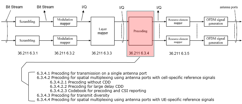
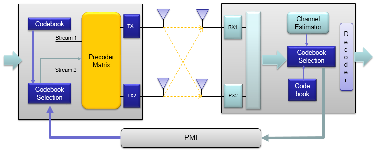
PrecodingUnfortunately I don't know how to explain this part in plain language without using any mathematical tools. As you see in the following diagram, Precoding is the process that is between Layer Mapper and Resource mapper. In practice, this precoding is the process in which the incoming data (=output of layer mapper) are distributed to each antenna ports. Then the question is "How each of the data (layered data) get distributed to each of antenna ports ?". Is it as simple like "data on layer 0 goes blindly to antenna port 1 and data on layer 1 goes blindly to antenna port 1". Unfortunately it is not that simple. In reality, the data from all the layers gets combined in specify way and then those combined data gets distributed to each of the antenna port. so we can roughly say "Each antenna ports carries at least some portions of data from all the layers". Then the question is "How (in what kind of rule) the data from all the layers get combined ?". The rule is defined by a precoding matrix that we will look into, in this page. Followings are the topics to be covered in this page.
Overall ProcessFirst I would suggest you to get a big picture on the role of the Procoding on the overal downlink physical layer process as highlighted below. One thing very tricky about Precoding in LTE is that there are so many variations and is very hard to figure out which one to be applied to which case. Just taking a look at the list of sub titles listed below whenever you have chance. If you go through this list more than 10 or 20 times, you would have some image on several different cases where different variations of precoding is used.
Precoding vs Transmission ModeEach of those variants of the precoding can be mapped to each of Transmission Mode and the number of Antenna also influence on which type of procoding will be used in a specific situation of Transmission Mode. Also, go through the following table whenever you have chance.
Precoding for Transmit DiversityFollowing is the case where a single layer data stream gets transmitted by two antenna. Overall procedure is as follows. (TM2, TM6 is using this configuration) If we apply the Layer 1 code book to a sequence of data, we will get the constellation as follows. If you briefly see the constellation, you don't find any differences in terms of constellation except overall amplitude gets smaller after going through the precoding block. But if you following through the precoding process for each one (single) constellation, you will understand the differences. The Octave code is here. (I create this code in Octave which is a Matlab like GNU program,but I guess it will run in Matlab without any modification. I tried to write the code so that I can run on both program but I haven't tested it in Matlab myself). In addition, I posted another type of tutorials that may help you with intuitive understandings on this kind of complex number operation. See my visual note [Matrix Complex] (this, this, this, this) to build up intuition. Precoding for Spatial Multiplexing - Precoding with large delay CDD
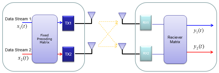
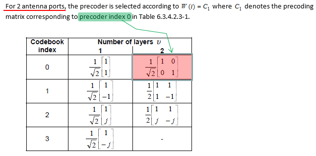
To make the process and understanding simpler, let's assume that we are only focusing on two antenna case. If it is two antenna case, the block diagram around the Precoding looks as follows. (TM3 is using this configuration) In case of Procoding with Large Delay CDD, two additional matrix are multiplied before it is multiplied by Procoding matrix as shown below. Please keep in mind the role of each matrix in the equation. (Refer to CDD page if you want to know further details of CDD concept itself) Then a question would come up. Where is W(i) matrix defined ? One or a couple of specially selected matrix from the codebook are used. Which matrix (which index) of the codebook is used are defined in the 36.211 as shown below.
The only way to understand this concept to the skin would be to try this yourself and play with all these parameters like your toys. To help this, I created a small octave code and attached here. (I create this code in Octave which is a Matlab like GNU program, but I guess it will run in Matlab without any modification. I tried to write the code so that I can run on both program but I haven't tested it in Matlab myself). I posted another type of tutorials that may help you with intuitive understandings on this kind of complex number operation. See my visual note [Matrix Complex] (this, this, this, this) to build up intuition.
Note : If I expand the transformation shown above into a 2 x 2 case to give you more concrete idea, it can be illustration as follows. Since all of the data used here are complex numbers (Real = I, Imaginary = Q), the result of operation may not be so intuitive to you. If you are really interested in understanding the result of transformation, try this transformation with your own program or pen-paper calculation on your own. At least, play with the matlab code that I created and linked here. Following is the real Downlink signal coming out of a LTE network emulator. I capture the signal and analyzed it with a vector spectrum analyzer with LTE analysis functionality. Now let try apply the CDD. I would recommend you to try investigate on what's is CDD in practical sense and what would be the advantage of applying CDD. Here I would only show you the result of the CDD application. The Octave code is here. (I create this code in Octave which is a Matlab like GNU program, but I guess it will run in Matlab without any modification. I tried to write the code so that I can run on both program but I haven't tested it in Matlab myself). I posted another type of tutorials that may help you with intuitive understandings on this kind of complex number operation. See my visual note [Matrix Complex] (this, this, this, this) to build up intuition. Precoding for Spatial Multiplexing - Precoding with the selected Codebook
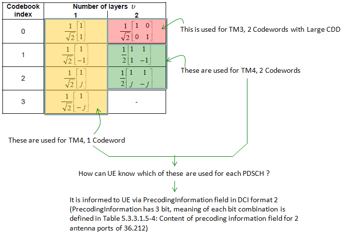
< Codebook selection for Precoding - 2 Antenna Ports >Getting one step deeper into the procedure, you may have a question asking "Which code book matrix (W(i)) do we have to use for each DL transmission ?". I think following table (Table 6.3.4.2.3-1 from 36.211) and the comments would answer the question.
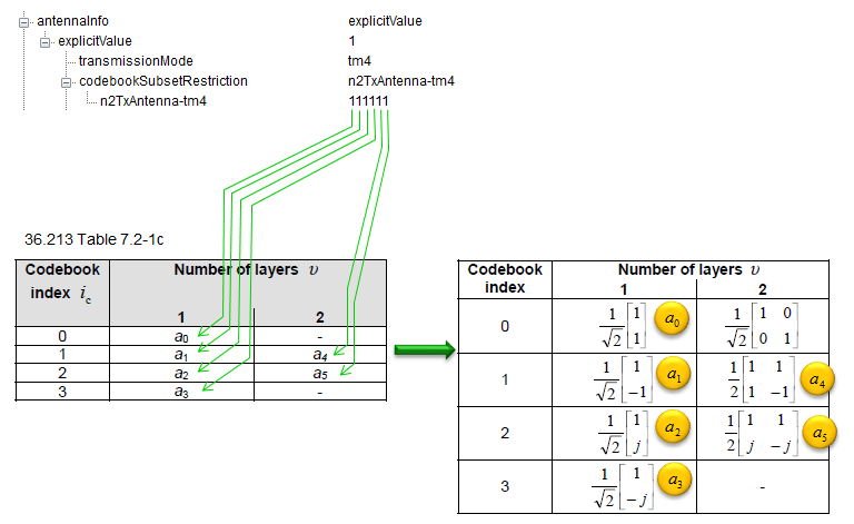
Even though we can use any of the items in this table, NW can specify which of the items will be used for each user(each connection) by defining codebookSubsetRestriction IE in .radioResourceConfigDedicated.physicalConfigDedicated.antennaInfo.
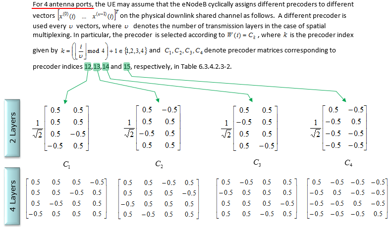
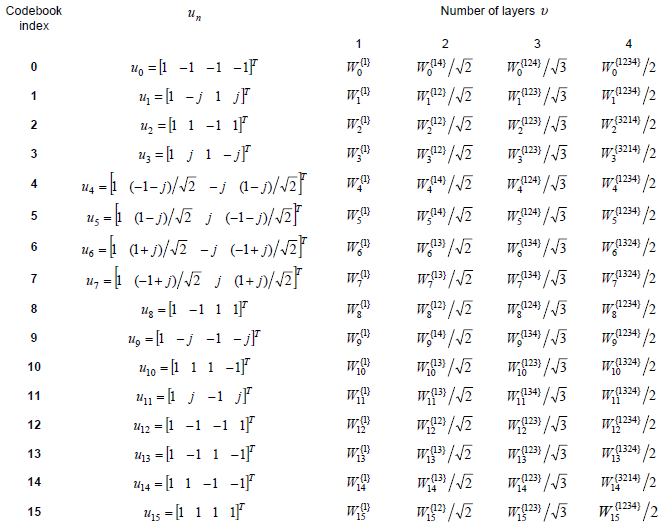
< Codebook selection for Precoding - 4 Antenna Ports >Following is from Table 6.3.4.2.3-2 of 36.211 (Table 6.3.4.2.3-2 Codebook for transmission on antenna ports {0,1,2,3}).
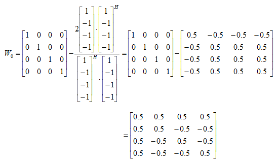
How to interpret this table ? I took me pretty long time to figure it out. You would not get the Precoding Matrix directly from this table. You need to go through a couple of intermediate steps before you get the matrix. First, you have to use following equation to calculate Wn. (Here you see a special symbol called 'Hermitian'. If you are not familiar with this, refere to Hermitian Matrix page)
Let's take u0 case as an example. u0 is defined as follows according to Table 6.3.4.2.3-2 of 36.211.
By plugging this into the Wn expression, you would get the result as follows.
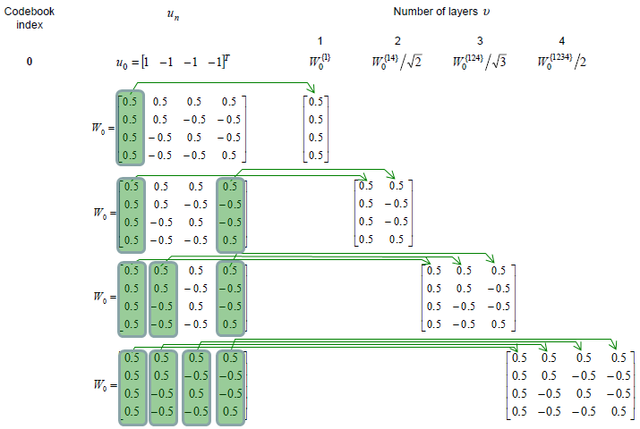
Once you get the Wn, getting W matrix for one, two, three, four antenna case is almost automatic. I think just following illustration would be self-explanatory (I hope -:)).
Following is Wn that I calculated for all the codebook index. (You can get the Octave code that I used here. I haven't tried with Matlab.. it is up to you checking it with Matlab). I will leave it up to you to figure out all the W matrix for one, two, three, four antenna on your own. You would never know what you don't know until you try on your own.
< Codebook for 4 x 2 MIMO >
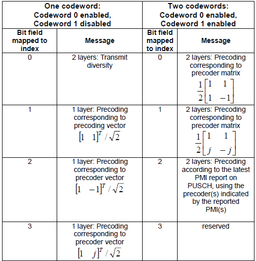
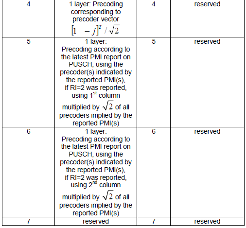
Precoding Information FieldIn previous sections, you have seen so many different precoding matrix. Then you may have ask "How eNB can inform of which matrix it used ?" or "How a UE can figure out which precoding matrix is used ?". eNodeB can inform UE of which codebook index is used by setting the PrecodingInformation field in DCI format 2 or 2A. < 36.212 Table 5.3.3.1.5-4: Content of precoding information field for 2 antenna ports >
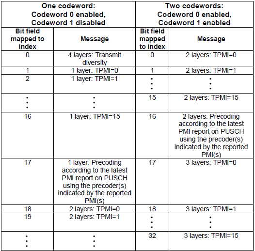
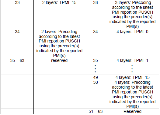
< 36.211 Table 5.3.3.1.5-5: Content of precoding information field for 4 antenna ports >
Tutorials on complex transformationAs I mentioned above, if you just see the overall constellation, you don't find any differences in terms of constellation except overall amplitude gets smaller after going through the precoding block. But if you following through the precoding process for each one (single) constellation, you will understand the differences. Following sequences of plots shows you 'Precoding' result of each points with each precoding (transformation) vector. Colored spots represents the constellation (I/Q data) coming(I/Q data) out of Layer Mapping block and coming into Precoding block. Black spots represents the constellation coming out of the Precoding block. You would notice that each of the colored spots creates two black spots. Even for the plot with only one black spots, it is the superimposed result of two black spots. Each of the black spots gets transmitted by each of the antenna. The Octave code is here. (I create this code in Octave which is a Matlab like GNU program, but I guess it will run in Matlab without any modification. I tried to write the code so that I can run on both program but I haven't tested it in Matlab myself). I posted another type of tutorials that may help you with intuitive understandings on this kind of complex number operation. See my visual note [Matrix Complex] (this, this, this, this) to build up intuition Followings are short description for each of dots (v) and vectors(tv).
|
||||||||||||||||||||||||||||||||||||||||||||||||||||||||||||||||||||||||||||||||||||||||||||||||||||||||||||||||||||||||||||||||||||||||||||||||
