A downlink or uplink grant is a handful of bits, and everything about the transmission it schedules follows from them. DCI is the name of those bits. This page takes the formats one at a time, and then decodes six real grants field by field.
When you study the physical frame structure of LTE, you may be impressed by flexibility (meaning complexity in other way) of all the possible ways of resource allocation. It was combination of Time Domain, Frequency Domain and the modulation scheme. Especially in frequency domain, you have so many resource blocks you can use (100 Resource Blocks in case of 20 Mhz Bandwidth) and if you think of all the possible permutation of these variables, the number of possible resource allocation will be very huge. Then you would have this question (At least I had this question).. How can the other party (the recieving side) can figure out exactly where in the slot and in which modulation scheme that the sender (transmitter) transmit the data(subframe)? I just captured the physical signal but how can I (the reciever) decode this signal. This is where the term called 'DCI(Downlink Control Indicator)' comes in.
It is DCI which carries those detailed information like "which resource block carries your data ?" and "what kind of demodulation scheme you have to use to decode data ?" and some other additional information. It means you (the reciever) first have to decode DCI and based on the information you got from the DCI you can decode the real data. It means without DCI, decodingthe data delivered to you is impossible.
Not only in LTE, but also in most of wireless communication the reciever requires special information structure like DCI. For example, in WCDMA R99, Slot format and TFCI carries those information and in HSDPA HS-SCCH carried those information and in HSUPA E-TFCI carries it.
Comparing to control channel in other technology (WCDMA, HSPA), LTE DCI has a lot more additional information in it. In addition to resource allocation, it can carry Power Control Command, CSI Report Request or CQI Report Request etc. There are several different DCI format, each of which has different set of intormations it can carry. Then Question would be which DCI format we have to use for a specific situation. This question will be answered in later part in this page.
In terms of protocol implementation with respect to carrying these information, R99 seems to be the most complicated one. You had to define all the possible combination of resource allocation in the form of TFCS (a kind of look-up table for TFCI) and you have to convey those information through L3 message (e.g, Radio Bearer Setup message and RRC Connection Setup message) and the transmitteralso have to configure itself according to the table. A lot of error meaning headache came from the mismatches between the TFCS information you configured in L3 message and the configuration the transmitter applied to itself (transmitter's lower layer configuration). It has been too much headache to me. HSDPA relieved the headache a lot since it carries these information directly on HS-SCCH and this job is done by MAC layer. The resource allocation information carried by HS-SCCH is called 'TFRI'. So I don't have to care much about L3 message.. but still I need to jump around the multiple different 3GPP document to define any meaningful TFRIs. And other complication was that even in HSDPA we still using R99 DPCH for power control and signaling purpose, so I cannot completely remove the headache of handling TFCS.Now in LTE, this information is carried by DCI as I explained above and we only have to care about just a couple of parameters like Number of RBs, the starting point of RBs and the modulation scheme and I don't have to care anything about configuring these things in RRC messages. This is a kind of blessing to me.
As one example showing how/when DCI is used, refer to "Uplink Data Transmission Scheduling - Persistent Scheduling"
- Types of DCIs
- DCI in Action
- What kind of information is carried by each DCI ?
- What determines a DCI Format for the specific situation ?
- Any relations between DCI format and Layer 3 signaling message ?
- RNTI vs DCI Format
- Channel Coding Process for DCI
- Full Details of Each DCI Contents
- Format 0 (Release 8) - C-RNTI, SPS C-RNTI
- Format 1 (Release 13) - C-RNTI, SPS C-RNTI
- Format 1A (Release 13) - C-RNTI, SPS C-RNTI
- Format 1A (Release 13) - C-RNTI : PDCCH Order
- Format 1A (Release 13) - RA-RNTI, P-RNTI, or SI-RNTI
- Format 1B (Release 8) - C-RNTI, SPS C-RNTI
- Format 1C (Release 8) - RA-RNTI, P-RNTI, or SI-RNTI
- Format 1C (Release 8) - M-RNTI
- Format 1D (Release 8) - C-RNTI, SPS C-RNTI
- Format 2 (Release 13) - C-RNTI, SPS C-RNTI
- Format 2A (Release 13) - C-RNTI, SPS C-RNTI
- Format 3 (Release 8) - TPC-RNTI
- Format 3A (Release 8) - TPC-RNTI
- DCI Format for Rel 10 or later
- DCI 0 - Examples
- DCI 1 - Examples
- DCI 2A - Examples
- From DCI to PDCCH
- Reference
Types of DCIs
Downlink Control Information is the message the network sends on the control channel to tell one UE what to do in one subframe. It is short, it is read before anything else in the subframe, and two kinds of instruction fill it.
DCI carries the following information :
i) UL resource allocation (persistent and non-persistent)
ii) Descriptions about DL data transmitted to the UE.
L1 signaling is done by DCI and Up to 8 DCIs can be configured in the PDCCH. These DCIs can have 6 formats : 1 format for UL scheduling, 2 formats for Non-MIMO DL scheduling, 1 format for MIMO DL Scheduling and 2 formats for UL power control.
DCI has various formats for the information sent to define resource allocations. The DCI formats defined in LTE are as follows.
|
DCI Format |
Usage |
Major Contents |
|
UL Grant. Resource Allocation for UL Data |
RB Assignment,TPC,PUSCH Hopping Flag |
|
|
DL Assignment for SISO |
RB Assignment,TPC, HARQ |
|
|
DL Assignment for SISO (compact) |
RB Assignment,TPC, HARQ |
|
|
Triggering RACH in Connected States |
PRACH Sequence Index |
|
|
DL Assignment for MIMO with Rank 1 |
RB Assignment,TPC, HARQ,TPMI, PMI |
|
|
DL Assignment for SISO (minimum size) |
RB Assignment |
|
|
DL Assignment for Multi User MIMO |
RB Assignment,TPC, HARQ,TPMI,DL Power Offset |
|
|
DL Assignment for Closed Loop MIMO |
RB Assignment,TPC, HARQ, Precoding Information |
|
|
DL Assignment for Open Loop MIMO |
RB Assignment,TPC, HARQ, Precoding Information |
|
|
DL Assignment for TM8 (Dual Layer Beamforming) |
RB Assignment,TPC, HARQ, Precoding Information |
|
|
DL Assignment for TM9 |
RB Assignment,TPC, HARQ, Precoding Information |
|
|
TPC Commands for PUCCH and PUSCH with 2 bit power adjustment |
Power Control Only |
|
|
TPC Commands for PUCCH and PUSCH with 1 bit power adjustment |
Power Control Only |
|
|
Format 4 |
UL Assignment for UL MIMO (up to 4 layers) |
RB Assignment,TPC, HARQ, Precoding Information |
L1 signaling is done by DCI and Up to 8 DCIs can be configured in the PDCCH. These DCIs can have 6 formats : 1 format for UL scheduling, 2 formats for Non-MIMO DL scheduling, 1 format for MIMO DL Scheduling and 2 formats for UL power control.
DCI in Action
At early LTE (before Rel 10), the operation mode in DCI (Resource Allocation) was pretty simple and straightforward (at least in FDD) as in < Case 1 >. However, as the technology evolves we started setting different variations of DCI operation. Now we have special types of LTE specially designed for IoT/M2M application and DCI operation has been changed even further. In this section, I will try to visualize several typical types of DCI operations as examples just to give you some big picture on how DCI works for PDSCH and PUSCH scheduling.
Case 1
This is the plain arrangement, and every case after it is a departure from this one. The red block at the front of each downlink subframe is the control region. The DCI sitting in it schedules either a PDSCH in the same subframe or a PUSCH further along the uplink row.

Case 2
A DCI does not have to travel in the control region. Here the legacy control region at the front of the subframe carries none at all, and the grant sits inside the data region instead, which is what the legend calls EPDCCH.

Case 3
Carrier aggregation adds a second carrier, and the first question it raises is where that carrier's grants come from. In this case each carrier answers for itself: the secondary carrier has a control region of its own, and it schedules its own data.

Case 4
This is the same pair of carriers with the secondary carrier's control region taken away. Every grant for that carrier now comes from the primary carrier's control region, and that is what cross carrier scheduling means.

Case 5
Coverage is the problem here rather than capacity. The control region carrying the DCI stretches across two consecutive subframes, so a UE at the edge of the cell collects the same grant twice before it decodes it.

What kind of information is carried by each DCI ?
The best way to understand this in very detail is to take one example of each of DCI bit string and decode manually based on 3GPP specification. But this section can be a good summary for quick reference. And the DCI decode examples at the end of this page would give you a good/detailed picture of DCI strutures.
Type 0 : A bitmap indicating the resource block groups(RBGs) that are allocated to the scheduled UE. (An RBG is a set of consecutive physical resource blocks(PRBs). This type has following informations
- Flag for format 0/format1A differentiation
- Hoping flag
- Resource block assignment and hopping resource allocation
- New data indicator
- TPC command for scheduled PUSCH
- Cyclic shift for DM RS
- CQI request
- Number of appended zeros to format 0
Type 1 : A bitmap indicating PRBs from a set of PRBs from a subset of resource block groups determined by the system bandwidth.
- Resource allocation header (resource allocation type 0/type 1)
- Resource block assignment
- Modulation and coding scheme
- HARQ process number
- New data indicator
- Redundancy version
- TPC command for PUCCH
Type 2 : A set of contiguously allocated physical or virtual resource blocks. The allocations vary from a single PRB upto the maximum number of PRBs spanning the system bandwidth.
What determines a DCI Format for the specific situation ?
A DCI format is not picked freely. It follows from what the grant is for and from how the cell has been configured, and the tables in this section are where 3GPP writes that choice down.
There are two major factors to determine a DCI format for a specific situation as follows :
i) RNTI Type
ii) Transmission Mode
This means that you cannot change only one of these parameters arbitrarily and you always have to think of the relationships among these when you change one of these parameters. Otherwise you will spend a long time for troubleshooting -:)
Those tables from 3GPP 36.213 shows the relationships between RNTI Type, Transmission Mode and DCI format. (You would notice that same information (same RNTI type) can have multiple candidates of DCI format. Then, the question is "How network determine which DCI format it has to use at a specific moment ?". In some case, you can find a clear criteria from following table, but some other case the selection criteria is not clear. For example, if you ask "Do I have to use DCI format 1A or 2A when I am using TM3, C-RNTI ?". You may say "Use DCI format 2A in MIMO configuration and use 1 A in non-MIMO configuration". But the answer would not be clear if you ask "What kind of DCI format (1A or 1C) for Paging message (P-RNTI) ?". At least table 7.1-2 does now show any different selection criteria and I haven't found anywhere else in the spec about this selection criteria. In this case, I just ask to several other people who is working on that specific area and trying to draw conclusion by a kind of 'vote'. For this specific case (DCI format for P-RNTI), I got the response saying "There is no clear criteria, it is just upto network on which one to pick".)
< 36.213-v14.6.0 Table 7.1-1: PDCCH and PDSCH configured by SI-RNTI >
|
DCI format |
Search Space |
Transmission scheme of PDSCH corresponding to PDCCH |
|
DCI format 1C |
Common |
If the number of PBCH antenna ports is one, Single-antenna port, port 0 is used , otherwise Transmit diversity . |
|
DCI format 1A |
Common |
If the number of PBCH antenna ports is one, Single-antenna port, port 0 is used , otherwise Transmit diversity . |
< 36.213-v14.6.0 Table 7.1-2: PDCCH and PDSCH configured by P-RNTI >
|
DCI format |
Search Space |
Transmission scheme of PDSCH corresponding to PDCCH |
|
DCI format 1C |
Common |
If the number of PBCH antenna ports is one, Single-antenna port, port 0 is used, otherwise Transmit diversity |
|
DCI format 1A |
Common |
If the number of PBCH antenna ports is one, Single-antenna port, port 0 is used , otherwise Transmit diversity |
< 36.213-v14.6.0 Table 7.1-3: PDCCH and PDSCH configured by RA-RNTI >
|
DCI format |
Search Space |
Transmission scheme of PDSCH corresponding to PDCCH |
|
DCI format 1C |
Common |
If the number of PBCH antenna ports is one, Single-antenna port, port 0 is used , otherwise Transmit diversity |
|
DCI format 1A |
Common |
If the number of PBCH antenna ports is one, Single-antenna port, port 0 is used , otherwise Transmit diversity |
< 36.213-v14.6.0 Table 7.1-5: PDCCH and PDSCH configured by C-RNTI>
|
Transmission mode |
DCI format |
Search Space |
Transmission scheme of PDSCH corresponding to PDCCH |
|
Mode 1 |
DCI format 1A |
Common and UE specific by C-RNTI |
Single-antenna port, port 0 |
|
DCI format 1 |
UE specific by C-RNTI |
Single-antenna port, port 0 |
|
|
Mode 2 |
DCI format 1A |
Common and UE specific by C-RNTI |
Transmit Diversity |
|
DCI format 1 |
UE specific by C-RNTI |
Transmit Diversity |
|
|
Mode 3 |
DCI format 1A |
Common and UE specific by C-RNTI |
Transmit Diversity |
|
DCI format 2A |
UE specific by C-RNTI |
Large delay CDD or Transmit Diversity |
|
|
Mode 4 |
DCI format 1A |
Common and UE specific by C-RNTI |
Transmit Diversity |
|
DCI format 2 |
UE specific by C-RNTI |
Closed-loop multiplexing or Transmit Diversity |
|
|
Mode 5 |
DCI format 1A |
Common and UE specific by C-RNTI |
Transmit Diversity |
|
DCI format 1D |
UE specific by C-RNTI |
Multi-user MIMO |
|
|
Mode 6 |
DCI format 1A |
Common and UE specific by C-RNTI |
Transmit Diversity |
|
DCI format 1B |
UE specific by C-RNTI |
Closed-loop multiplexing using a single transmission layer |
|
|
Mode 7 |
DCI format 1A |
Common and UE specific by C-RNTI |
If the number of PBCH antenna ports is one, Single-antenna port, port 0 is used , otherwise Transmit diversity |
|
DCI format 1 |
UE specific by C-RNTI |
Single-antenna port, port 5 |
|
|
Mode 8 |
DCI format 1A |
Common and UE specific by C-RNTI |
If the number of PBCH antenna ports is one, Single-antenna port, port 0 is used , otherwise Transmit diversity |
|
DCI format 2B |
UE specific by C-RNTI |
Dual layer transmission, port 7 and 8 or single-antenna port, port 7 or 8 |
|
|
Mode 9 |
DCI format 1A |
Common and UE specific by C-RNTI |
Non-MBSFN
subframe: If the number of PBCH antenna ports is one, Single-antenna port,
port 0 is used, otherwise Transmit diversity |
|
DCI format 2C |
UE specific by C-RNTI |
Transmit diversity, port 7-8, or dual layer transmission port 7-8 , if UE is configured with higher layer parameter semiOpenLoop, up to 8 layer transmission, ports 7-14 otherwise; or single-antenna port, port 7, 8, 11, or 13 if UE is configured with higher layer parameter dmrs-tableAlt, single-antenna port, port 7 or 8 otherwise |
|
|
Mode 10 |
DCI format 1A |
Common and UE specific by C-RNTI |
Non-MBSFN
subframe: If the number of PBCH antenna ports is one, Single-antenna port,
port 0 is used, otherwise Transmit diversity |
|
DCI format 2D |
UE specific by C-RNTI |
Transmit diversity, port 7-8, or dual layer transmission port 7-8 , if UE is configured with higher layer parameter semiOpenLoop, up to 8 layer transmission, ports 7-14 otherwise; or single-antenna port, port 7, 8, 11, or 13 if UE is configured with higher layer parameter dmrs-tableAlt, single-antenna port, port 7 or 8 otherwise |
< 36.213-v14.6.0 Table 7.1-7: PDCCH and PDSCH configured by Temporary C-RNTI>
|
DCI format |
Search Space |
Transmission scheme of PDSCH corresponding to PDCCH |
|
DCI format 1A |
Common and UE specific by C-RNTI |
If the number of PBCH antenna port is one, Single-antenna port, port 0 is used , otherwise Transmit diversity |
|
DCI format 1 |
UE specific by C-RNTI |
If the number of PBCH antenna port is one, Single-antenna port, port 0 is used , otherwise Transmit diversity |
Corner Case Situation
Even though all the tables listed above provide the selection criteria for various situation, there still be some cases which sounds like a corner case or gray area.
Case 1 : Single Transport Block Scheduling with 2, 2A, 2B, 2C and 2D
Q1 > In terms of fields in these DCI format, they all carries the scheduling for two transport blocks. Can I still schedule single transport block PDSCH with these DCI format ? If yes, what should I set for the field of Transport block where are not scheduled ?
A1> Yes, it is possible. Both MCS and RV of unscheduled transport should be set to 0 in this case as per following statement at 36.213-7.1.7.2 :
DCI formats 2, 2A, 2B, 2C and 2D a transport block is disabled if 0 MCS I = and if rvidx = 1 otherwise the transport block is enabled
Q2 > Assuming CQI is not reported, which PUCCH format should be used for this case ? 1a or 1b?
A2> 1a
Any relations between DCI format and Layer 3 signaling message ?
Yes, there is a relationship. You have to know which DCI format is required for which RRC message. Following tables from 3GPP 36.321 shows the relationship between RNTI and logical channel and you would know which RRC message is carried by which logical channel. So with two step induction, you will figure out the link between RRC message and it's corresponding DCI format.

- Each row names one RNTI, the use it is put to, the transport channel that carries it and the logical channel above that.
- P-RNTI sits against PCCH and SI-RNTI against BCCH, which is how a paging message or a system information message is recognised before anything in it is read.
- C-RNTI appears on two rows. The first is dynamically scheduled unicast on DL-SCH and UL-SCH, carrying DCCH and DTCH; the second triggers PDCCH ordered random access and carries no channel at all.
- Semi-Persistent Scheduling C-RNTI appears twice for the same reason, once for activation, reactivation and retransmission and once for deactivation.
- The last two rows, TPC-PUCCH-RNTI and TPC-PUSCH-RNTI, read N/A in both channel columns. A grant addressed to them carries no data, only power control.
For example, if you see the "Security Mode Command" message of section 6.2.2 of 36.331, it says
Signalling radio bearer: SRB1
RLC-SAP: AM
Logical channel: DCCH
Direction: UE to E-UTRAN
If you see the table, you would see this message is using C-RNTI. and you will figure out the possible candiates from table 7.1-5 of 36.213 and if you would have detailed information of the transmission mode, you can pinpoint out exactly which DCI format you have to use for this message for a specific case. Assuming TM mode in this case is TM1 and scheduling is dynamic scheduling, if you see Table 7.1-2 you will figure out that this is using C-RNTI. With this RNTI Type and TM mode, if you see table 7.1-5, this case use DCI Format 1 or DCI Format 1A.
The two steps are worth keeping apart, because each one uses a different table. 36.321 Table 7.1-2 takes you from the logical channel that the RRC message names to the RNTI that carries it. 36.213 Table 7.1-5 then takes you from that RNTI and the transmission mode to the formats that are allowed. Neither table answers the question on its own.
RNTI vs DCI Format
Just for Convenience, I created a table that shows RNTI types and DCI Format that can be used for each RNTI. (You can figure this out by combining the descriptions of various tables in previous section.)
|
RNTI Types |
DCI Format Applicable to the RNTI Type |
|
SI-RNTI, P-RNTI, RA-RNTI |
1A, 1C |
|
C-RNTI, SPS C-RNTI |
0, 1A, 1B, 1D, 2, 2A, 2B, 2C, 4 (2B,2C,4 is for Rel 10 or later) |
|
M-RNTI |
1C |
|
TPC-RNTI |
3, 3A |
- SI-RNTI, P-RNTI and RA-RNTI share one row and one answer. All three use the compact formats, 1A and 1C, and none of them can use a two codeword format, because none of them is addressed to a UE whose transmission mode the network knows.
- C-RNTI is the only row with a long list, and that is the point of it. It is the identity under which a UE has a transmission mode, so the transmission mode is free to select among the formats.
- The TPC-RNTI row stands for two identities. 36.321 Table 7.1-2 splits it into TPC-PUCCH-RNTI and TPC-PUSCH-RNTI, one for each power control loop, and format 3 or 3A is used under either of them.
- The note in the second row is the table's own currency warning: 2B, 2C and 4 belong to Release 10 and later, and the page on DCI for LTE Advanced covers them.
Full Details of Each DCI Contents
A lot of complications resides in the composition (structure) of each DCI Format. This is a huge topic and requires a lot of cross referencess among multiple specification. I would just start with DCI format 0 and I think it would take a couple of weeks to complete this section.
NOTE 1: The structure of each DCI format is defined in 36.212 5.3.3.1 DCI formats but many of the fields in a DCI are defined in many other specifications. I tried to consolidate all the different specifications in this single page, so that you can get all the informations here without opening multiple specifications.
NOTE 2: Most of these tables are based on Release 8 specification. Some of field name might have been changed in later specification.
NOTE 3 : DCI for LTE Advanced is not described here. I wrote a separate pages for DCI for LTE Advanced.
DCI Format 0
Format 0 carries an uplink grant. 36.212 gives it one job, the scheduling of PUSCH in one uplink cell, and every field listed below serves that job.
This is based on 3GPP 36.212 - 5.3.3.1.1 Format 0.
|
Field Name |
Length |
Comment |
|
Flag for format0/format1A differentiation |
1 |
|
|
Hopping flag |
1 |
|
|
N_ULhop |
1 (1.4 Mhz) 1 (3 Mhz) 1 (5 Mhz) 2 (10 Mhz) 2 (15 Mhz) 2 (20 Mhz) |
Applicable only when Hopping flag is set.(Refer to 36.213 Table 8.4-1 and Table 8.4-2)is. |
|
Resource block assignment |
5 (1.4 Mhz) 7 (3 Mhz) 7 (5 Mhz) 11 (10 Mhz) 12 (15 Mhz) 13 (20 Mhz) |
See 36.213 8.1 |
|
MCS and RV |
5 |
|
|
NDI (New Data Indicator) |
1 |
|
|
TPC for PUSCH |
2 |
See Power Control section |
|
Cyclic shift for DM RS |
3 |
See 36.211 Table Table 5.5.2.1.1-1 |
|
UL index (TDD only) |
2 |
This field is present only for TDD operation with uplink-downlink configuration 0 |
|
Downlink Assignment Index (DAI) |
2 |
set only in TDD Operation with uplink-downlink configurations 1-6 |
|
CSI request (1 or 2 bit) |
1,2,3,4,5 (Refer to this table) |
This field is used to trigger Aperiodic CSI report from UE based on 36.213 7.2.1. In case of Aperiodic Report in Carrier Aggregation, Refer to this page. |
< 36.213 Table 8.4-1: Number of Hopping Bits NUL_hop vs. System Bandwidth >

< 36.213 Table 8.4-2: PDCCH DCI Format 0 Hopping Bit Definition >

< 36.213 8.1 Resource Allocation for PDCCH DCI Format 0 >

< 36.211 Table 5.5.2.1.1-1: Mapping of Cyclic Shift Field in DCI format 0 to DMRS(2)_n Values >

< 36.213 Table 7.3-X: Value of Downlink Assignment Index >

The screenshot is an earlier form of this table. In 36.213 v19.4.0 the same Table 7.3-X reads 2 or 6 or 10 in the second row rather than 2 or 6. Its last column now counts subframes or slots, and it names PDCCH, EPDCCH or SPDCCH. A separate table, 7.3.1-1, counts the same field across serving cells instead of across subframes, and there the count runs as far as 32.
< CSI bit length decision table >
NOTE : This table is summary of 36.212 v17.1 - 5.3.3.1.1 Format 0 - CSI request
|
CSI-RS-ConfigNZPAperiodic |
numberActivatedAperiodicCSI-RS-Resources |
Search Space |
No of DL Cell |
CSI process |
CSI measurement setst |
No of CSI bits |
|
Not Configured |
N/A |
uss |
<= 5 |
N/A |
N/A |
2 |
|
Not Configured |
N/A |
uss |
<= 5 |
> 1 |
N/A |
2 |
|
Not Configured |
N/A |
uss |
<= 5 |
> 1 |
2 |
2 |
|
Configured |
1 |
uss |
<= 5 |
N/A |
N/A |
2 |
|
Configured |
1 |
uss |
<= 5 |
> 1 |
N/A |
2 |
|
Configured |
1 |
uss |
<= 5 |
> 1 |
2 |
2 |
|
Configured |
1 |
otherwise |
1 |
|||
|
Not Configured |
N/A |
otherwise |
1 |
|||
|
Not Configured |
N/A |
uss |
>= 6 |
N/A |
N/A |
3 |
|
Configured |
1 |
uss |
>= 6 |
N/A |
N/A |
3 |
|
Configured |
>1 |
uss |
<= 5 |
N/A |
N/A |
4 |
|
Configured |
>1 |
uss |
<= 5 |
> 1 |
N/A |
4 |
|
Configured |
>1 |
uss |
<= 5 |
> 1 |
2 |
4 |
|
Configured |
>1 |
uss |
>= 6 |
N/A |
N/A |
5 |
|
Configured |
>1 |
otherwise |
3 |
|||
DCI Format 1
Format 1 is the general downlink grant. It schedules one PDSCH codeword in one cell, which means a single transport block and no spatial multiplexing to describe.
This is based on 3GPP 36.212 - 5.3.3.1.2 Format 1.
|
Field Name |
Length (Bits) |
Comment |
|
Resource allocation header |
1 |
RA Type 0 or RA Type 1 |
|
Resource block assignment for RA Type 0 |
6 (1.4 Mhz) 8 (3 Mhz) 13 (5 Mhz) 17 (10 Mhz) 19 (15 Mhz) 25 (20 Mhz) |
Applicable only when Resource allocation header = 0 (RA Type 0) Refer to RA Type page |
|
Subset |
N/A (1.4 Mhz) 1 (3 Mhz) 1 (5 Mhz) 2 (10 Mhz) 2 (15 Mhz) 2 (20 Mhz) |
Applicable only when Resource allocation header = 1 (RA Type 1) Refer to RA Type page |
|
Shift |
N/A (1.4 Mhz) 1 (3 Mhz) 1 (5 Mhz) 1 (10 Mhz) 1 (15 Mhz) 1 (20 Mhz) |
Applicable only when Resource allocation header = 1 (RA Type 1) Refer to RA Type page |
|
Resource block assignment for RA Type 1 |
N/A (1.4 Mhz) 6 (3 Mhz) 13 (5 Mhz) 14 (10 Mhz) 16 (15 Mhz) 22 (20 Mhz) |
Applicable only when Resource allocation header = 1 (RA Type 1) Refer to RA Type page |
|
MCS |
5 |
|
|
HARQ Process |
3 (FDD) 4 (TDD) |
|
|
RV |
2 |
|
|
TPC for PUCCH |
2 |
See Power Control section |
|
Downlink Assignment Index |
X |
Set only in TDD See 36.212 - Table 5.3.3.1.2-2 See DAI page for the details of DAI concept |
|
HARQ-ACK resource offset |
2 |
Set only when DCI is carried by EPDCCH |
< 36.212 - Table 5.3.3.1.2-2: Number of bits for Downlink Assignment Index. >
|
No of Bits |
Description |
|
4 |
For UEs configured by higher layers with codebooksizeDetermination-r13 = dai and when a DCI format scheduling PDSCH is mapped onto the UE specific search space given by the C-RNTI as defined in 36.213, the 4-bit DAI consists of a 2-bit counter DAI and a 2-bit total DAI. - Counter DAI – 2 bits as defined in section 7.3 of 36.213 - Total DAI – 2 bits as defined in section 7.3 of 36.213 |
|
2 |
For UEs configured with no more than five DL cells, or for UEs configured by higher layers with codebooksizeDetermination-r13 = cc, or for UEs configured by higher layers with codebooksizeDetermination-r13 = dai and when a DCI format scheduling PDSCH is not mapped onto the UE specific search space given by the C-RNTI as defined in 36.213, this field is present forFDD or TDD operation, for cases with TDD primary cell. If the UL/DL configuration of all TDD serving cells is same and the UE is not configured to decode PDCCH with CRC scrambled by eimta-RNTI, then this field only applies to serving cell with UL/DL configuration 1-6 If at least two TDD serving cells have different UL/DL configurations or the UE is configured to decode PDCCH with CRC scrambled by eimta-RNTI, then this field applies to a serving cell with DL-reference UL/DL configuration 1-6 as defined in section 10.2 of 36.213 |
|
0 |
For UEs configured with no more than five DL cells, or for UEs configured by higher layers with codebooksizeDetermination-r13 = cc, or for UEs configured by higher layers with codebooksizeDetermination-r13 = dai and when a DCI format scheduling PDSCH is not mapped onto the UE specific search space given by the C-RNTI as defined in 36.213, this field is not present for FDD or TDD operation, for cases with FDD primary cell. |
DCI Format 1A
Format 1A is the compact downlink grant. It schedules one PDSCH codeword in one cell, and it also carries the random access procedure that a PDCCH order starts, which is why it appears outside ordinary scheduling.
This is based on 3GPP 36.212 - 5.3.3.1.3 Format 1A.
|
Field Name |
Length (Bits) |
Comment |
|
Flag for format0/format1A differentiation |
1 |
|
|
Localized/Distributed VRB assignment flag |
1 |
|
|
N_Gap |
1 |
Applicable only when Localized/Distributed VRB assignment flag is 1 (Distributed) and BW >= 10 Mhz 0 = N-Gap 1 1 = N-Gap 2 |
|
Resource block assignment for Localized DRB |
5 (1.4 Mhz) 7 (3 Mhz) 9 (5 Mhz) 11 (10 Mhz) 12 (15 Mhz) 13 (20 Mhz) |
See 36.213 8.1 |
|
Resource block assignment for Distributed DRB |
5 (1.4 Mhz) 7 (3 Mhz) 9 (5 Mhz) 10 (10 Mhz) 11 (15 Mhz) 12 (20 Mhz) |
See 36.213 8.1 |
|
MCS |
5 |
|
|
HARQ Process |
3 (FDD) 4 (TDD) |
|
|
RV |
2 |
|
|
TPC for PUCCH |
2 |
See Power Control section |
|
Downlink Assignment Index |
X |
Set only in TDD See 36.212 - Table 5.3.3.1.2-2 See DAI page for the details of DAI concept |
|
SRS Request |
0 or 1 |
only for DCI/PDCCH in UE specific Search space |
|
HARQ-ACK resource offset |
2 |
Set only when DCI is carried by EPDCCH |
|
Field Name |
Length (Bits) |
Comment |
|
Flag for format0/format1A differentiation |
1 |
|
|
Localized/Distributed VRB assignment flag |
0 |
|
|
Resource block assignment for Localized DRB |
5 (1.4 Mhz) 7 (3 Mhz) 9 (5 Mhz) 11 (10 Mhz) 12 (15 Mhz) 13 (20 Mhz) |
All bit should be 1 |
|
Preamble Index |
6 |
|
|
PRACH Mask Index |
4 |
|
|
All the remaining bits |
All 0 |
|
|
Field Name |
Length (Bits) |
Comment |
|
Flag for format0/format1A differentiation |
1 |
|
|
Localized/Distributed VRB assignment flag |
1 |
|
|
N_Gap |
1 |
Applicable only when Localized/Distributed VRB assignment flag is 1 (Distributed) and BW >= 10 Mhz 0 = N-Gap 1 1 = N-Gap 2 |
|
Resource block assignment for Localized DRB |
5 (1.4 Mhz) 7 (3 Mhz) 9 (5 Mhz) 11 (10 Mhz) 12 (15 Mhz) 13 (20 Mhz) |
See 36.213 8.1 |
|
Resource block assignment for Distributed DRB |
5 (1.4 Mhz) 7 (3 Mhz) 9 (5 Mhz) 10 (10 Mhz) 11 (15 Mhz) 12 (20 Mhz) |
|
|
MCS |
5 |
|
|
HARQ Process |
3 (FDD) 4 (TDD) |
|
|
NDI |
1 |
Applicable only if DL BW >≥ 5 Mhz and Localized/Distributed VRB assignment flag is set to 1 |
|
RV |
2 |
|
|
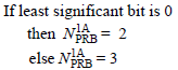
TPC (MSB) |
1 (Reserved) |
|
|
TPC (LSB) |
1 |
 |
|
Downlink Assignment Index |
X |
Set only in TDD See 36.212 - Table 5.3.3.1.2-2 See DAI page for the details of DAI concept |
|
HARQ-ACK resource offset |
2 |
Set only when DCI is carried by EPDCCH |
DCI Format 1B
Format 1B is format 1A with precoding added. It schedules one PDSCH codeword in one cell and names the precoder to use, so it belongs to closed loop transmission on a single layer.
This is based on 3GPP 36.212 - 5.3.3.1.3A Format 1B.
|
Field Name |
Length (Bits) |
Comment |
|
Flag for format0/format1A differentiation |
1 |
|
|
Localized/Distributed VRB assignment flag |
1 |
|
|
N_Gap |
1 |
Applicable only when Localized/Distributed VRB assignment flag is 1 (Distributed) and BW >= 10 Mhz 0 = N-Gap 1 1 = N-Gap 2 |
|
Resource block assignment for Localized DRB |
5 (1.4 Mhz) 7 (3 Mhz) 9 (5 Mhz) 11 (10 Mhz) 12 (15 Mhz) 13 (20 Mhz) |
See 36.213 8.1 |
|
Resource block assignment for Distributed DRB |
5 (1.4 Mhz) 7 (3 Mhz) 9 (5 Mhz) 10 (10 Mhz) 11 (15 Mhz) 12 (20 Mhz) |
See 36.213 8.1 |
|
MCS |
5 |
|
|
HARQ Process |
3 (FDD) 4 (TDD) |
|
|
RV |
2 |
|
|
TPC for PUCCH |
2 |
See Power Control section |
|
TPMI information for precoding |
2 (2 Antenna) 4 (4 Antenna) |
Refer to following pages for details : |
|
PMI confirmation for precoding |
1 |
See 36.212 Table 5.3.3.1.3A-2 for details |
< 36.212 Table 5.3.3.1.3A-2: Content of PMI confirmation >

DCI Format 1C
Format 1C is the smallest downlink grant on this page. It schedules one PDSCH codeword very compactly, and the system uses it for the messages that go to everybody: notifying an MCCH change, direct indication, reconfiguring TDD and carrying LAA common information.
This is based on 3GPP 36.212 - 5.3.3.1.4 Format 1C.
|
Field Name |
Length (Bits) |
Comment |
|
N_Gap |
1 |
Applicable only when Localized/Distributed VRB assignment flag is 1 (Distributed) and BW >= 10 Mhz 0 = N-Gap 1 1 = N-Gap 2 |
|
Resource block assignment |
3 (1.4 Mhz) 5 (3 Mhz) 7 (5 Mhz) 6 (10 Mhz) 8 (15 Mhz) 9 (20 Mhz) |
|
|
MCS |
5 |
|
|
Field Name |
Length (Bits) |
Comment |
|
MCCH Change Notification |
8 |
|
|
Reserve |
N/A (1.4 Mhz) 2 (3 Mhz) 4 (5 Mhz) 5 (10 Mhz) 6 (15 Mhz) 7 (20 Mhz) |
|
DCI Format 1D
Format 1D is format 1B with one more field. It schedules one PDSCH codeword with precoding and with a downlink power offset, and that offset is what multi user MIMO needs when two UEs share the same resource.
This is based on 3GPP 36.212 - 5.3.3.1.4A Format 1D.
|
Field Name |
Length (Bits) |
Comment |
|
Flag for format0/format1A differentiation |
1 |
|
|
Localized/Distributed VRB assignment flag |
1 |
|
|
N_Gap |
1 |
Applicable only when Localized/Distributed VRB assignment flag is 1 (Distributed) and BW >= 10 Mhz 0 = N-Gap 1 1 = N-Gap 2 |
|
Resource block assignment for Localized DRB |
5 (1.4 Mhz) 7 (3 Mhz) 9 (5 Mhz) 11 (10 Mhz) 12 (15 Mhz) 13 (20 Mhz) |
See 36.213 8.1 |
|
Resource block assignment for Distributed DRB |
5 (1.4 Mhz) 7 (3 Mhz) 9 (5 Mhz) 10 (10 Mhz) 11 (15 Mhz) 12 (20 Mhz) |
See 36.213 8.1 |
|
MCS |
5 |
|
|
HARQ Process |
3 (FDD) 4 (TDD) |
|
|
RV |
2 |
|
|
TPC for PUCCH |
2 |
See Power Control section |
|
TPMI information for precoding |
2 (2 Antenna) 4 (4 Antenna) |
Refer to following pages for details : |
|
Downlink power offset |
1 |
See 36.213 Table 7.1.5-1 for details |

DCI Format 2
Format 2 is the two codeword downlink grant for closed loop spatial multiplexing. 36.213 Table 7.1-5 pairs it with transmission mode 4, and its precoding information field names the precoder the eNB applied.
This is based on 3GPP 36.212 - 5.3.3.1.5 Format 2.
|
Field Name |
Length (Bits) |
Comment |
|
Resource allocation header |
1 |
RA Type 0 or RA Type 1 |
|
Resource block assignment for RA Type 0 |
6 (1.4 Mhz) 8 (3 Mhz) 13 (5 Mhz) 17 (10 Mhz) 19 (15 Mhz) 25 (20 Mhz) |
Applicable only when Resource allocation header = 0 (RA Type 0) Refer to RA Type page |
|
Subset |
N/A (1.4 Mhz) 1 (3 Mhz) 1 (5 Mhz) 2 (10 Mhz) 2 (15 Mhz) 2 (20 Mhz) |
Applicable only when Resource allocation header = 1 (RA Type 1) Refer to RA Type page |
|
Shift |
N/A (1.4 Mhz) 1 (3 Mhz) 1 (5 Mhz) 1 (10 Mhz) 1 (15 Mhz) 1 (20 Mhz) |
Applicable only when Resource allocation header = 1 (RA Type 1) Refer to RA Type page |
|
Resource block assignment for RA Type 1 |
N/A (1.4 Mhz) 6 (3 Mhz) 13 (5 Mhz) 14 (10 Mhz) 16 (15 Mhz) 22 (20 Mhz) |
Applicable only when Resource allocation header = 1 (RA Type 1) Refer to RA Type page |
|
TPC for PUCCH |
2 |
See Power Control section |
|
Downlink Assignment Index |
X |
Set only in TDD See 36.212 - Table 5.3.3.1.2-2 See DAI page for the details of DAI concept |
|
HARQ Process |
3 (FDD) 4 (TDD) |
|
|
Transport block to codeword swap flag |
1 |
|
|
MCS for Transport Block 1 |
5 |
|
|
NDI for Transport Block 1 |
1 |
|
|
RV for Transport Block 1 |
2 |
|
|
MCS for Transport Block 1 |
5 |
|
|
NDI for Transport Block 1 |
1 |
|
|
RV for Transport Block 1 |
2 |
|
|
Precoding information |
3 (2 Antenna) 6 (4 Antenna) |
Refer to Precoding Information Field in Precoding Page |
|
HARQ-ACK resource offset |
2 |
Set only when DCI is carried by EPDCCH |
DCI Format 2A
Format 2A carries two codewords as well, but for open loop spatial multiplexing. 36.213 Table 7.1-5 pairs it with transmission mode 3, and 36.212 leaves the precoding information field out altogether when the cell has two antenna ports.
This is based on 3GPP 36.212 - 5.3.3.1.5A Format 2A.
|
Field Name |
Length (Bits) |
Comment |
|
Resource allocation header |
1 |
RA Type 0 or RA Type 1 |
|
Resource block assignment for RA Type 0 |
6 (1.4 Mhz) 8 (3 Mhz) 13 (5 Mhz) 17 (10 Mhz) 19 (15 Mhz) 25 (20 Mhz) |
Applicable only when Resource allocation header = 0 (RA Type 0) Refer to RA Type page |
|
Subset |
N/A (1.4 Mhz) 1 (3 Mhz) 1 (5 Mhz) 2 (10 Mhz) 2 (15 Mhz) 2 (20 Mhz) |
Applicable only when Resource allocation header = 1 (RA Type 1) Refer to RA Type page |
|
Shift |
N/A (1.4 Mhz) 1 (3 Mhz) 1 (5 Mhz) 1 (10 Mhz) 1 (15 Mhz) 1 (20 Mhz) |
Applicable only when Resource allocation header = 1 (RA Type 1) Refer to RA Type page |
|
Resource block assignment for RA Type 1 |
N/A (1.4 Mhz) 6 (3 Mhz) 13 (5 Mhz) 14 (10 Mhz) 16 (15 Mhz) 22 (20 Mhz) |
Applicable only when Resource allocation header = 1 (RA Type 1) Refer to RA Type page |
|
TPC for PUCCH |
2 |
See Power Control section |
|
Downlink Assignment Index |
X |
Set only in TDD See 36.212 - Table 5.3.3.1.2-2 See DAI page for the details of DAI concept |
|
HARQ Process |
3 (FDD) 4 (TDD) |
|
|
Transport block to codeword swap flag |
1 |
|
|
MCS for Transport Block 1 |
5 |
|
|
NDI for Transport Block 1 |
1 |
|
|
RV for Transport Block 1 |
2 |
|
|
MCS for Transport Block 2 |
5 |
|
|
NDI for Transport Block 2 |
1 |
|
|
RV for Transport Block 2 |
2 |
|
|
Precoding information |
0 (2 Antenna) 2 (4 Antenna) |
Refer to 36.212 Table 5.3.3.1.5A-2 for the meaning of value in the field |
|
HARQ-ACK resource offset |
2 |
Set only when DCI is carried by EPDCCH |
< 36.212 Table 5.3.3.1.5A-2: Content of precoding information field for 4 antenna ports >

DCI Format 3
Format 3 carries no scheduling at all. It is a block of transmit power control commands addressed to a group of UEs, each command two bits wide, and a UE reads only the position the network assigned to it.
This is based on 3GPP 36.212 - 5.3.3.1.6 Format 3.
|
Field Name |
Length (Bits) |
Comment |
|
TPC command number 1 |
2 |
|
|
TPC command number 2 |
2 |
|
|
TPC command number 3 |
2 |
|
|
... |
||
|
TPC command number N |
2 |
The size of N is dependent on the payload size of DCI format 0 for the system BW |
Which TPC value out of N values in DCI format 3 is used for a specific UE is specified by the RRC message as shown below.

DCI Format 3A
Format 3A does the same job as format 3 with narrower commands. Each power adjustment is a single bit rather than two, so the same block of bits reaches twice as many UEs.
This is based on 3GPP 36.212 - 5.3.3.1.7 Format 3A.
|
Field Name |
Length (Bits) |
Comment |
|
TPC command number 1 |
1 |
|
|
TPC command number 2 |
1 |
|
|
TPC command number 3 |
1 |
|
|
... |
||
|
TPC command number N |
1 |
The size of N is dependent on the payload size of DCI format 0 for the system BW |
Which TPC value out of N values in DCI format 3A is used for a specific UE is specified by the RRC message as shown below.

DCI Format for Rel 10 or later
Release 10 and the releases after it add formats this section does not cover, among them 2B, 2C and 4. They belong with the carrier aggregation and multi user MIMO features that introduced them, and they have a page of their own.
For this, refer to DCI for LTE Advanced.
DCI 0 - Examples
The three examples below take a real format 0 grant as a hexadecimal value and read it field by field, first as a table and then as a decoder shows it. All three come from a 10 MHz FDD cell, and that is what fixes the length at 27 bits.
Example 1 > DCIFormat 0, value = 0x2584A800 (00100101100001001010100000000000 b)
You can figure out the Start of RB and N_RB (Number of allocated RB) from RIV value.
|
Field |
Bit Length |
Value |
|
Format0-A-Flag |
1 |
0(DciFormat 0) |
|
Frequency Hopping |
1 |
0 (non Hopping) |
|
RIV |
11 |
1200 |
|
MCS |
5 |
18 |
|
NDI |
1 |
1 |
|
TPC |
2 |
01 |
|
Cyclic Shift |
3 |
000 |
|
CQI Request |
1 |
0 |
How can I calcuate Start_RB and N_RB from RIV. The simple calcuation is as follows :
i) N_RB = Floor(RIV/MAX_N_RB) + 1= Floor(1200/50) + 1 = 25, where MAX_N_RB = 50 in this case since this is 10 Mhz System BW.
ii) Start_RB = RIV mod MAX_N_RB = 1200 mod 50 = 0
Following is the decoding result from DCI Decoder

- The decoder reads the cell first. FDD, 10 MHz, which is 50 PRBs, one transmit antenna port and transmission mode 1: that is what fixes the length at 27 bits.
- Frequency hopping is off, and the resource allocation comes out as 25 PRBs starting at PRB 0, which is half the band.
- MCS 18 gives 16QAM and a transport block size of 9144 bits. The decoder notes beside it that the modulation would be QPSK instead if TTI bundling were configured.
- Redundancy version 0 means the block goes out with its first redundancy version, and the CQI request bit is 0, so this grant asks for no aperiodic report.
Example 2 > DCIFormat 0, value = 0x48720800 (01001000011100100000100000000000 b )
This examples shows the case where PUSCH frequency hopping flag is on. Depending on the value for NUL-hop, the detailed hopping pattern is determined.
|
Field |
Bit Length |
Value |
|
Format0-A-Flag |
1 |
0(DciFormat 0) |
|
Frequency Hopping |
1 |
1 (Hopping) |
|
NUL-hop |
2 |
00 |
|
RIV |
9 |
270 |
|
MCS |
5 |
8 |
|
NDI |
1 |
0 |
|
TPC |
2 |
01 |
|
Cyclic Shift |
3 |
000 |
|
CQI Request |
1 |
0 |
When the system band frequency is 1.4M, 3M, 5M, Type PUSCH hopping is decided by below method.
"NUL-hop" = 0 --- Type1
"NUL-hop" = 1 --- Type2
When the system band frequency is 10M, 15M, 20M, Type PUSCH hopping is decided by below method.
"NUL-hop" = 0 --- Type1
"NUL-hop" = 1 --- Type1
"NUL-hop" = 2 --- Type1
"NUL-hop" = 3 --- Type2
Following is the decoding result from DCI Decoder

- The hopping flag is set in this one, and that is the difference from the example above.
- Two hopping bits are present, because the band is 50 PRBs, and they read 0. The decoder resolves that to hopping type 1.
- The allocation is 6 PRBs starting at PRB 20 in the first slot. The decoder leaves the second slot's starting PRB undetermined, because it depends on parameters the grant itself does not carry.
- MCS 8 gives QPSK and a transport block size of 808 bits.
Example 3 > DCIFormat 0, value = 0x07D7E800 (00000111110101111110100000000000 b)
This example shows you a case with UL HARQ retransmission. If you see the MCS value, it says 31 which is set as RVidx 3 in Table 8.6.1-1 of 36.213.
|
Field |
Bit Length |
Value |
|
Format0-A-Flag |
1 |
0(DciFormat 0) |
|
Frequency Hopping |
1 |
0 (non Hopping) |
|
RIV |
11 |
250 |
|
MCS |
5 |
31 |
|
NDI |
1 |
1 |
|
TPC |
2 |
01 |
|
Cyclic Shift |
3 |
000 |
|
CQI Request |
1 |
0 |
Following is the decoding result from DCI Decoder

- MCS 31 is not a modulation order. The decoder shows the modulation type and the transport block size both as reuse previous, so the UE keeps whatever the earlier transmission of this block used.
- Redundancy version 3 goes with that reading. The grant is a retransmission, and the redundancy version is the only part of the coding that changes.
- The new data indicator reads 1. What separates a new block from a retransmission is the toggling of this bit, not its value. One grant read on its own therefore cannot settle that question, while the MCS and the redundancy version can.
DCI 1 - Examples
Both examples below are format 1A rather than format 1, and they are nearly the same grant twice. The first allocates localized virtual resource blocks and the second distributed ones, which is the clearest way to see what that one flag costs. The redundancy version differs between them as well.
Example 1 > DCIFormat 1A, value = 0x84B3C040 (10000100101100111100000001000000 b)
|
Field |
Bit Length |
Value |
|
Format1-A-Flag |
1 |
1(DciFormat 1A) |
|
ResourceAllocation |
1 |
0 (LocalizedVRB) |
|
RIV |
11 |
150 |
|
MCS |
5 |
15 |
|
HARQ Process |
3 |
0 |
|
NDI |
1 |
0 |
|
RV |
2 |
00 |
|
TPC |
2 |
10 |
Following is the decoding result from DCI Decoder

- The virtual resource block flag is 0, localized, so the allocation maps straight onto 4 physical resource blocks starting at PRB 0.
- MCS 15 gives 16QAM and a transport block size of 1128 bits.
- The grant uses HARQ process 0, and redundancy version 0 sends the block with its first redundancy version.
- The decoder labels the TPC field TPC command for PUCCH and reads it as 1. It is a real power control command here, because the grant is addressed by C-RNTI. Under P-RNTI, RA-RNTI or SI-RNTI the same two bits mean something else: a number of resource blocks. The Format 1A section above reproduces that rule.
Example 2 > DCIFormat 1A, value = 0xC4B3C140 (11000100101100111100000101000000 b)
|
Field |
Bit Length |
Value |
|
Format1-A-Flag |
1 |
1(DciFormat 1A) |
|
ResourceAllocation |
1 |
1 (DistributedVRB) |
|
Ngap |
1 |
0 (Ngap-0) |
|
RIV |
11 |
150 |
|
MCS |
5 |
15 |
|
HARQ Process |
3 |
0 |
|
NDI |
1 |
0 |
|
RV |
2 |
1 |
|
TPC |
2 |
01 |
Following is the decoding result from DCI Decoder

- The change that matters here is the virtual resource block flag, now 1 for distributed.
- That brings the gap into play. The table reads the gap field as 0, the decoder names that selection Gap 1, and the gap itself comes out as 27 resource blocks.
- The decoder therefore lists a scattered set of physical resource blocks for each slot, rather than the single contiguous run of the example above, and the two slots do not use the same blocks.
- MCS 15, 16QAM and a transport block size of 1128 bits are unchanged. The redundancy version is 1 here rather than 0.
DCI 2A - Examples
The example below is a two codeword downlink grant, so it carries two of several things: two modulation and coding scheme fields, two new data indicators and two redundancy versions. It also carries the flag that decides which codeword each transport block goes to.
Example 1 > DCIFormat 2A, value = 0x080005C080 (0000100000000000000001011100000010000000 b)
|
Field |
Bit Length |
Value |
|
ResourceAllocation |
1 |
0(RAType0) |
|
RB-Assign |
17 |
00010000000000000 |
|
TPC |
2 |
00 |
|
HARQ Process |
3 |
2 |
|
TB-CW Swap Flag |
1 |
1 |
|
MCS-TB1 |
5 |
24 |
|
NDI-TB1 |
1 |
0 |
|
RV-TB1 |
2 |
0 |
|
MCS-TB2 |
5 |
16 |
|
NDI-TB2 |
1 |
0 |
|
RV-TB2 |
2 |
0 |
Following is the decoding result from DCI Decoder


- The decoder reads two transmit antenna ports and transmission mode 3, and at that configuration the grant is 41 bits long.
- Resource allocation type 0 with a resource block group size of 3: one group is set in the 17 bit assignment field, which is 3 PRBs.
- The HARQ process is 2 and the TPC command is 0.
- The transport block to codeword swap flag is 1, and the decoder states the result in words: the codewords are swapped.
- Transport block 1 takes MCS 24, 64QAM and 1608 bits; transport block 2 takes MCS 16, 16QAM and 904 bits. Neither is disabled, so both are carried.
- There is no precoding information field anywhere in the decode. 36.212 leaves it out of format 2A for a two port cell, and this cell has two ports.
From DCI to PDCCH
You may see the structure of DCI looks too complicated. However, this would be taken as simple comparing to the procedure through which this DCI information has to go to get transmitted through Antenna. DCI that is described above is MAC layer concept and at least you can decode and understand the meaning of each bit field with relatively small effort. Since this is another huge topic and it is transport/physical layer issue, I described these issues in a couple of different pages as linked below.
The overall flow of channel coding to Resource Eelement mapping process for DCI is described in Physical Layer Channel : Downlink : PDCCH (Physical Download Control Channel)
The location of a PDCCH that carries a DCI (even though it is the exactly identical information) varies at every subframe. The location of the PDCCH is determined by CCE Index at transmitter (eNB). But this CCE index is not informed to the reciever (UE). UE has to figure out the location of PDCCH by blind decoding. This process is described in CCE Index Calculation/PDCCH Decoding/Blind Decoding.
When UE is trying blind decoding, how many different combinations of possible PDCCH allocation area (Search Space) ? This is described in PDCCH Candidate and Search Space
How many physical layer bits (how many Resource Elements) a PDCCH occupy when it is being transmitted ? This is explained in PDCCH Resource Allocation.
If you are not faimilar with the PDCCH allocation unit called CCE and how the REG gets distributed over control channel region. Refer to Resource Allocation and Management Unit
If you want to look in further details at the matlab code level, refer to Matlab :ToolBox : LTE : Downlink : PDCCH. This is not a full detail since it is based on Matlab Toolbox and the implementations of the toolbox function is not open to user, but you would get pretty good understandings of overall transport/physical channel process for DCI.
Reference
The documents below are the sources for the tables and formats reproduced on this page. A version is named only where the text was read in that version.
- 36.212 : 3GPP - E-UTRA; Multiplexing and channel coding, v19.3.0. Clause 5.3.3.1 defines every DCI format, and it is where the field lists on this page come from.
- 36.213 : 3GPP - E-UTRA; Physical layer procedures, v19.4.0. Clause 7.1 pairs each transmission mode with the DCI formats it may use, clause 7.3 is the HARQ-ACK procedure behind the Downlink Assignment Index, and clause 8 holds the uplink resource allocation rules reproduced here.
- 36.211 : 3GPP - E-UTRA; Physical channels and modulation. The source of the cyclic shift mapping screenshot in the Format 0 section.
- 36.321 : 3GPP - E-UTRA; Medium Access Control (MAC) protocol specification. The source of the RNTI usage table.