Matlab Toolbox - 4G/LTE
I have created around 10 separate posts just to explain how to create a single complete subframe. In this post, I will show you how to create a whole radio frame which is made up of 10 subframes. Overall logic is simple. I will just repeat the single subframe creation process ten times with different subframe numbers. In real situation, you may see the differences not only in subframe number, but also a lot of other properties (e.g, CFI, PDCCH composition, PDSCH composition etc).
A radio frame lasts 10 ms and holds 10 subframes of 1 ms. With the normal cyclic prefix, each subframe has 14 OFDM symbols, so the grid of one frame has 140 columns. Some channels appear in every subframe, and others only in subframe 0 or in subframes 0 and 5. The plot of a whole frame shows that difference in one picture.
Followings are the topics to be covered in this page.
SISO - Generating Modulation Data for 1 radio frame
How does one subframe become a whole radio frame? The code below runs the subframe routine of the earlier pages ten times, once for each value of NSubframe, and appends each resource grid to the right of the previous one. The cell uses one antenna, 6 RB and CFI 1.
% First you have to define properites of a eNodeB.
% NDLRB indicate System Bandwith in the unit of RBs.
% NDLRB 6 = 1.4 Mhz, NDLRB 15 = 3.0 Mhz, NDLRB 25 = 5.0 Mhz,
% NDLRB 50 = 10 Mhz, NDLRB 75 = 15 Mhz, NDLRB 100 = 20 Mhz
% CellRefP indicate number of downlink Antenna. CellRefP = 1 means 1 transmission antenna (SISO)
% NCellID indicate PCI (Physical Cell Identity) of the Cell
% NSubframe indicate the subframe number.
% In this example, most of these parameters are kept same for all subframe, but NSubframe value will be
% changed. so NSubframe will be set within the for loop.
enb.CyclicPrefix = 'Normal';
enb.PHICHDuration = 'Normal';
enb.Ng = 'Sixth';
enb.NDLRB = 6;
enb.CellRefP = 1;
enb.DuplexMode = 'FDD';
enb.NFrame = 0;
enb.NCellID = 0;
enb.CFI = 1;
% Now I will create an array variabel that will store all the subframe. It is initiailized with the empty array.
txFrameGrid = [];
% Now I will create a simple for loop and within the for loop I put the routine for creating all the signal and
% channel creation routing for each subframe. I just copied the whole routine from PDSCH creation example.
for subframeNo = 0:9 % start of for loop
% As I said, the enb paramters that does not change for each subframe is placed out side of the for loop
% I only put the chaning parameter (NSubframe) in this example within the forloop and associate it with
% for loop counter. Of course, which parameter you want to change for each subframe is up to you.
enb.NSubframe = subframeNo;
% Now populate all the information in DCI field as you like. Understanding details of DCI is also pretty
% huge topics. You would need separate page for DCI for the details.
dci.NDLRB = enb.NDLRB;
dci.DCIFormat = 'Format1A';
dci.AllocationType = 0;
dci.Allocation.RIV = 18;
dci.ModCoding = 10;
dci.HARQNo = 0;
dci.NewData = 0;
dci.TPCPUCCH = 0;
dci.DuplexMode = 'FDD';
dci.NTxAnts = 1;
% once you defined all the detailed fields of DCI, just pass it to lteDCI() function with eNB info as follows,
% then you will get the bit stream for the DCI.
[dciMessage,dciMessageBits] = lteDCI(enb,dci);
% for this step, you need to set a couple of additional parameters as shown below.
% C_RNTI will be XORed to CRC bits
% PDCCHFormat will determined Aggregation Level.
% PDCCHFormat 0 indicate Aggregation Level 1
% PDCCHFormat 1 indicate Aggregation Level 2
% PDCCHFormat 2 indicate Aggregation Level 4
% PDCCHFormat 3 indicate Aggregation Level 8
C_RNTI = 100;
pdcchConfig.RNTI = C_RNTI;
pdcchConfig.PDCCHFormat = 0;
% then pass dciMessageBits and pdcchConfig to lteDCIEncode, the you would get the encoded bitstream.
codedDciBits = lteDCIEncode(pdcchConfig, dciMessageBits);
% If you pass the enb into ltePDCCHInfo() function, it will give you the amount of resources that can be
% allocated for PDCCH allocation. This is not the amount of resource for only one DCI. It will give you the
% total/maximum amount of the resources that can be allocated for PDCCH.
pdcchDims = ltePDCCHInfo(enb);
% With ltePDCCHSpace, you can get the list of all the possible spaces that can carry PDCCH.
% In this example, the space were shown in the unit of bits.
pdcchBits = -1*ones(pdcchDims.MTot, 1);
% generate an array with the length that can accommodate all the possible PDCCH bits.
candidates = ltePDCCHSpace(enb, pdcchConfig, {'bits', '1based'});
% select one of the candidate bitSection and assign the codedDcitBits. You can select any candidate bit
%vsection, but in this example, I selected the first candidate section.
pdcchBits ( candidates(1, 1) : candidates(1, 2) ) = codedDciBits;
% if pass the encodedBits into ltePDCCH(), it will generate the modulated physical layer symbols.
pdcch_sym = ltePDCCH(enb, pdcchBits);
pdcch_sym_ind = ltePDCCHIndices(enb,{'1based','re'});
pdcch_sym_arrayIndex = 0:length(pdcch_sym)-1;
% Now we set various parameters defining PDSCH channel. (In real transmission, you would need to create
% a dci that is corresponding the configuration here. But in this example, I will go without defining DCI)
pdsch.NTxAnts = 1;
pdsch.NLayers = 1;
pdsch.TxScheme = 'Port0';
pdsch.Modulation = {'16QAM'};
pdsch.RV = 0;
pdsch.RNTI = C_RNTI;
% Now I have to create a vector carrying the number of PRB indexes that will be used to carry this PDSCH.
% for example, pdsch_prbs in following section would create a vector [0 1 2 3]
START_RB = 0;
N_RB = 4;
pdsch_prbs = (START_RB:(START_RB+N_RB-1)).';
% Now we have to generate a bit sequence which would exactly fit to the number of resource elements
% that are allocated for PDSCH for this specific subframe.
% To figure out exact Resource Element information, unlike in other channel processing, I would run
% ltePDSCHIndices() first. As you see in the following code, ltePDSCHIndices() returns the information that
%vwould give you the size of transport block size in the unit of bits.
[pdsch_sym_ind,pdschIndInfo] = ltePDSCHIndices(enb,pdsch,pdsch_prbs,{'1based','re'});
codedTrBlkSize = pdschIndInfo.G;
% now I would create a bit array that carries the user data. In this example, I generated randomly but
% in real situation, this would carry your user data (e.g, image, movie, files etc)
dlschTransportBlk = round(rand(1,codedTrBlkSize));
% now if you pass all the information to lteDLSCH), it will generate the encoded codeword data for the
% transport block you defined.
codeword = lteDLSCH(enb,pdsch,codedTrBlkSize,dlschTransportBlk);
% now if you pass the encoded data (codeword) with eNB and pdsch config to ltePDSCH(), you can
% generate physical layer symbols for the encoded data.
pdsch_sym = ltePDSCH(enb,pdsch,codeword);
pdsch_sym_arrayIndex = 0:length(pdsch_sym)-1;
% Following is to create an empty resource grid for one subframe.
resourceGrid = lteDLResourceGrid(enb);
% Following is to create symbols for Cell Specific Reference Signal and make a list of resource index for the
% reference signal.
rsAnt0 = lteCellRS(enb,0);
indAnt0 = lteCellRSIndices(enb,0);
resourceGrid(indAnt0) = rsAnt0;
% Following is to create symbols for PBCH and make a list of resource index for the signal (channel)
mib_bits = lteMIB(enb);
bch_cw = lteBCH(enb,mib_bits);
pbch_sym = ltePBCH(enb,bch_cw);
pbch_sym_arrayIndex = 0:length(pbch_sym)-1;
pbch_sym_ind = ltePBCHIndices(enb,{'1based','re'});
% Following is to create symbols for PSS and make a list of resource index for the signal
pss = ltePSS(enb);
pss_arrayIndex = 0:length(pss)-1;
pss_sym_ind = ltePSSIndices(enb,0,{'1based','re'});
% Following is to create symbols for SSS and make a list of resource index for the signal
sss = lteSSS(enb);
sss_arrayIndex = 0:length(sss)-1;
sss_sym_ind = lteSSSIndices(enb,0,{'1based','re'});
% Following is to create symbols for PCFICH and make a list of resource index for the signal
cfi_cw = lteCFI(enb);
pcfich_sym = ltePCFICH(enb,cfi_cw);
pcfich_sym_arrayIndex = 0:length(pcfich_sym)-1;
pcfich_sym_ind = ltePCFICHIndices(enb,{'1based','re'});
% Following is to create symbols for PHICH and make a list of resource index for the signal
PHICH_Group_Index = 0;
PHICH_Sequence_Index = 1;
HARQ_Indicator_Value = 0; % 0 = NACK, 1 = ACK
phich_sym = ltePHICH(enb,[PHICH_Group_Index,PHICH_Sequence_Index,HARQ_Indicator_Value]);
phich_sym_arrayIndex = 0:length(phich_sym)-1;
phich_sym_ind = ltePHICHIndices(enb,{'1based','re'});
% Following part is filling the resource grid with each of the signal.. but if you see carefully I didn't fill this
% with real symbol number, I just filled it with a constant that I arbitrarily set. This is just for visualization..
% just to allocate constant/outstanding color for each signal. When you use this resource grid for real
% transmission (not for visualization), fill the resourceGrid with real symbol value you generated above.
pss_scale = 0.2;
sss_scale = 0.4;
phich_scale = 0.7;
pcfich_scale = 0.5;
pbch_scale = 0.7;
pdcch_scale = 0.9;
pdsch_scale = 0.6;
resourceGrid(pss_sym_ind) = pss_scale .* pss;
resourceGrid(sss_sym_ind) = sss_scale .* sss;
resourceGrid(pcfich_sym_ind) = pcfich_scale .* pcfich_sym;
resourceGrid(phich_sym_ind) = phich_scale .* phich_sym;
resourceGrid(pbch_sym_ind) = pbch_scale .* pbch_sym(1:length(pbch_sym_ind));
resourceGrid(pdcch_sym_ind) = pdcch_scale .* pdcch_sym;
resourceGrid(pdsch_sym_ind) = pdsch_scale; % .* pdsch_sym;
% Now We just completed the process of creating a subframe.
% Next step is to store this subframe to the variable we created for storing the whole radio frame.
txFrameGrid = [txFrameGrid resourceGrid];
end; % end of for loop
% Now we are at the last step. That is plot the whole data stored in txFrameGrid.
xStep = 0:((14*10)-1);
yStep = 0:(enb.NDLRB*12-1);
surface(xStep,yStep,abs(txFrameGrid));
axis([0 (14*10) 0 (enb.NDLRB*12-1) 0 1]);
view([0,90]);
set(gca,'xtick',[0:14:140]);
set(gca,'ytick',[[0:12:enb.NDLRB*12-1] [enb.NDLRB*12-1]]);
The loop keeps every eNB parameter fixed except enb.NSubframe. Each pass creates an empty grid with lteDLResourceGrid, fills it with the CRS, PBCH, PSS, SSS, PCFICH, PHICH, PDCCH and PDSCH, and appends it with txFrameGrid = [txFrameGrid resourceGrid]. After ten passes, txFrameGrid has 72 rows and 140 columns: 6 x 12 subcarriers and 10 x 14 OFDM symbols.
Each channel is multiplied by its own scale constant, as on the OFDM Symbol Extraction page, so each channel gets its own colour in the plot. The PDSCH line is different: the code writes pdsch_scale alone, because .* pdsch_sym is commented out. The PDSCH REs therefore all have the value 0.6 and appear in one flat colour. The function surface draws abs(txFrameGrid) with the OFDM symbol on the x axis and the subcarrier on the y axis.
The plot below shows the whole frame. The x axis has a tick at the start of each subframe, every 14 symbols, and the y axis has a tick at the start of each RB, every 12 subcarriers.
|
enb.NDLRB = 6; enb.CellRefP = 1; enb.NCellID = 0; enb.CFI = 1;
START_RB = 0; N_RB = 4; |
|
|
|
|
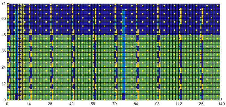
One radio frame with 6 RB. The PDSCH fills subcarriers 0 to 47, RB 0 to 3, in every subframe. The PBCH appears in symbols 7 to 10 of subframe 0 only. The SSS and PSS appear in symbols 5 and 6 of subframes 0 and 5, at x = 5, 6, 75 and 76.
One loop pass per subframe : only enb.NSubframe changes.txFrameGrid is 72 by 140 : 6 RB by 10 subframes of 14 symbols.PDSCH written as a constant : .* pdsch_sym is commented out.
Reading the radio frame grid
The plot looks like one subframe copied ten times, but it is not. This section reads the frame column by column. It explains which channels repeat in every subframe and which appear only in some of them, with the clause of 36.211 that places each one.
The table below lists what the plot shows in each part of the frame. The OFDM symbol numbers count from 0 at the start of each subframe.
Channel | Where in the frame | Colour in the plot |
CRS | symbols 0, 4, 7 and 11 of every subframe, every 6 subcarriers | yellow dots |
PCFICH, PHICH, PDCCH | symbols 0 and 1 of every subframe | mixed, with yellow for the PDCCH |
PDSCH | symbols 2 to 13 of every subframe, subcarriers 0 to 47 | green |
PBCH | symbols 7 to 10 of subframe 0 | olive |
SSS | symbol 5 of subframes 0 and 5, central 62 subcarriers | light blue |
PSS | symbol 6 of subframes 0 and 5, central 62 subcarriers | blue |
The PSS and SSS repeat every 5 ms, in the last two symbols of the first slot of subframes 0 and 5, as 36.211 v19.3.0 clause 6.11 sets for FDD. The PBCH takes the first four symbols of the second slot of subframe 0 only, from clause 6.6.4. Its period is 10 ms, and one MIB is spread over four frames. At 6 RB, both the synchronization signals and the PBCH cover almost the whole carrier, so the PDSCH on RB 0 to 3 is absent from those symbols.
The control region takes symbols 0 and 1 in every subframe, although the code sets CFI = 1. 36.211 Table 6.7-1 gives CFI + 1 symbols for PDCCH when the carrier has 10 RB or fewer. The layout inside the control region can change from subframe to subframe. The code keeps the first candidate of ltePDCCHSpace, and in the UE-specific search space of 36.213 clause 9.1.1 the starting CCE depends on the RNTI and on the subframe number. The PDCCH page shows that search space in detail.
Subcarriers 48 to 71, RB 4 and RB 5, carry no PDSCH. Outside subframes 0 and 5, they show only the CRS dots and the control region, and the rest stays at zero, the dark blue of the plot. In a real cell, the scheduler would fill them with PDSCH for other UEs, or with OCNG in a test setup.
CRS, control region and PDSCH : in every subframe.PSS and SSS : subframes 0 and 5, every 5 ms.PBCH : subframe 0 only, every 10 ms.CFI 1 gives 2 control symbols at 6 RB : 36.211 Table 6.7-1.
Disclaimer !
This page is only to show you the overall logics and visualization for various LTE physical layer channels. I haven't investigated much about verifying about the accuracy.
If you think the code is not so efficient, it is 100% my fault. I haven't made any effort for effiecient code. I just tried to create code as simple as possible for the readers. As you know, easy-to-read code is not always efficient for a specific chipset.
If you find any mistake in terms of accuracy, it is also very highly likely be my fault. Not the problem of Matlab tool box itself.
Any comment and corrections if you find any mistake will be welcome and appreciated.
Reference
[1] 3GPP TS 36.211 v19.3.0 - clauses 6.2, 6.6.4, 6.10.1.2 and 6.11, and Table 6.7-1: resource grid, PBCH, CRS, synchronization signals and PDCCH symbols
[2] 3GPP TS 36.213 v19.4.0 - clause 9.1.1, PDCCH assignment procedure