When you are thinking of LTE Advanced, the first feature you would think would be `Carrier Aggregation`. And when you think of Carrier Aggregation, the first question you may ask would be "If a UE is getting data from multiple carriers, how can it report ACK/NACK ?"
Followings are the list of topics that will be described in further details in this page.
- Format 1b with Channel Selection
- RRC Message Mapping - Format 1b
- Format 3
- Which PUCCH format to use ?
- PUCCH format 4 and format 5
- Reference
With this question in mind,you may easily guess that we may need some additional way to handle this situation and this is main motivation of having additional PUCCH format as shown below. Just compare the following specs, you would notice that we have longer list in Release 10. (Refer to 36.213, 10.1.1 PUCCH format information)
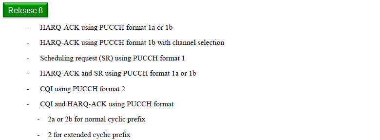
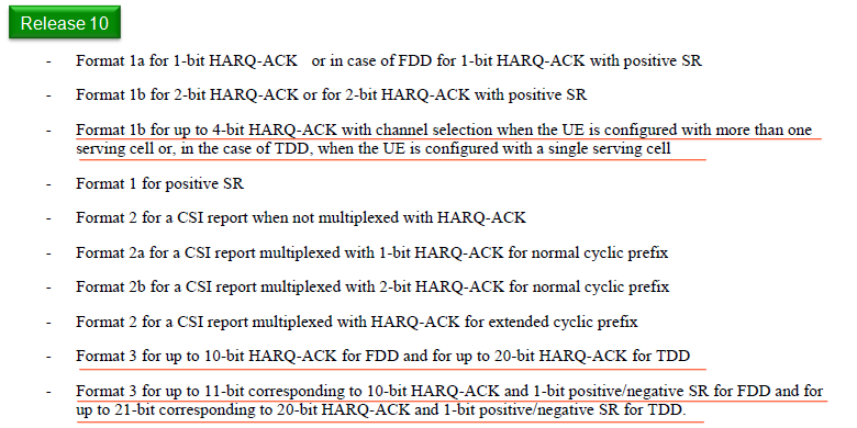
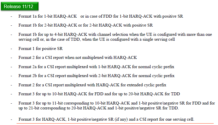
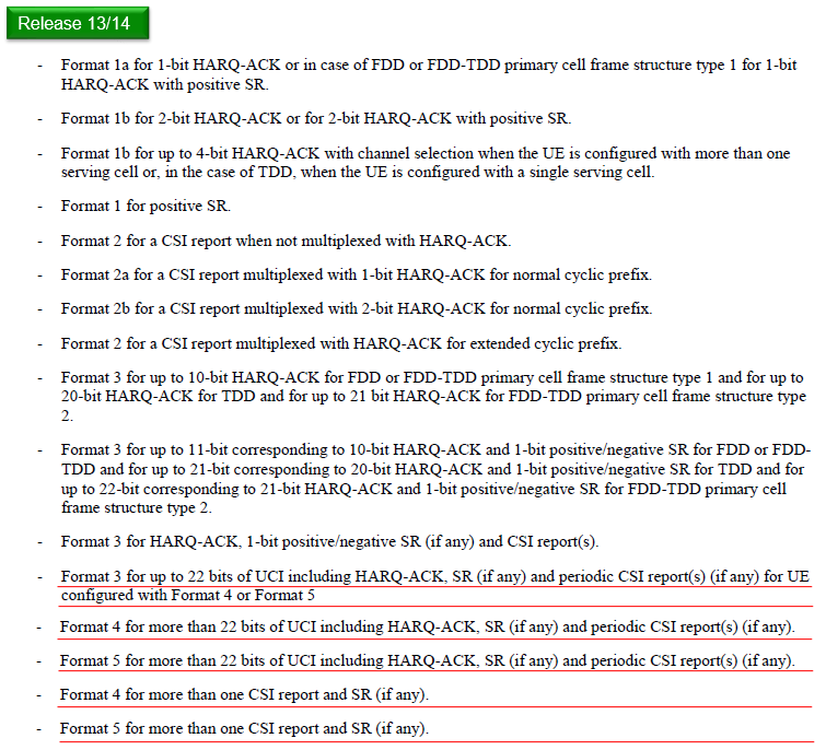
The same clause of 36.213 at four points in its life. Each release keeps every line of the one above it and adds to the bottom of the list.
Channel selection is already in Release 8 : the line reads HARQ-ACK using PUCCH format 1b with channel selection, with no bit count and no mention of serving cells.Release 10 adds a number and a condition : up to 4-bit HARQ-ACK, and only when the UE has more than one serving cell, or a single one on TDD.Format 3 arrives as two lines, not one : one for up to 10-bit HARQ-ACK on FDD and 20-bit on TDD, and one for the same totals plus an SR bit.Release 11 and 12 add exactly one line : format 3 for HARQ-ACK, 1-bit SR if any, and a CSI report for one serving cell.Release 13 and 14 add formats 4 and 5 : four lines give them more than 22 bits of UCI, and a fifth caps format 3 at 22 bits when either is configured.
That last block is where this page stops and the specification does not. Formats 4 and 5 are named on the picture above and nowhere in the text below it, so they have a section of their own at the foot of this page.
The list has kept growing since. 36.213 v19.4.0 splits every format 3, 4 and 5 entry by transmission duration, so each one now reads subframe-PUCCH, slot-PUCCH or subslot-PUCCH. One sentence at the end of the clause saves reading all of them. Slot-PUCCH supports only formats 1, 1a, 1b, 3 and 4. Subslot-PUCCH supports only formats 1, 1a, 1b and 4.
Now let's think again more seriously on the question "If a UE is getting data from multiple carriers, how can it report ACK/NACK ?"
If you are a designer, how do you handle this ? I think anybody might think of following options.
- Option 1 : Let UE send 'ACK' only when it was successful to decode PDSCH from all component carriers and transmit NACK if any of PDSCH is failed to be decoded. --> This is technically possible, you would clearly see this would be very inefficient way and cause a lot of unnecessary retransmission. So this method is not considered in real implementation.
- Option 2 : Let UE send ACK or NACK for each carrier separately. --> This would not sound perfect way, but we can reuse the existing PUCCH format without much modification.
- Option 3 : Let UE send ACK or NACK for each carrier on a single PUCCH. --> This would sound the best, but you can easily guess we would need a new PUCCH format since all the existing PUCCH format (Rel 8 format) is designed to send ACK/NAC for one carrier.
In real implementation (specification), Option 2 and 3 are adopted. Two new PUCCH types are introduced for Carrier Aggregation. 'PUCCH format 1b with channel selection' and PUCCH format 3 are those new types.
'PUCCH format 1b with channel selection' can support maximum 2 Carriers only and PUCCH format 3 can support up to 5 carriers in release 11 and 12 and support up to 10 carriers in release 13 and 14.
Format 1b with Channel Selection
Format 1b is not a new one. It was there for LTE release 8, but it has been extended to send 4 bit HARQ-ACK/NACK in LTE advanced. The extension is not a new field and not a new modulation. It is a rule that reads the choice of PUCCH resource as carrying information, on top of the two bits the format already sends.
In this section, you would see one of the most complicated and confusing tables in the whole LTE specification (at least to me, it was the most confusing one). The interpretation of the table is even more confusing.
My first question was why they designed ACK/NACK transmission mechanism in such a akward/confusing manner ?
Of course, 3GPP specification never gives any explicit answer to this kind of question. With a lot of thinking and talking to other expert engineers, I personally came to the conclusion that we need to use this kind of strange way because PUCCH 1b can carry only two bits of data, which means it can carry only 4 different state information. But the number of possible ACK/NACK/DTX combination for two carriers is much larger than that. In case of 2 CC MIMO, there can be 81 different combinations. Definately it is impossible to handle this kind of combination with only 2 bit information. Due to this bit size restriction, they decided to use PUCCH position as a kind of additional status bits. We use N1PUCCH for this purpose and we can have 4 different values for this parameter.
Getting confused already ?
I fully understand how you feel about this. Just pass on and see if you have clearer understanding after you go through the specific examples in this page.
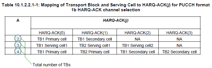
A is the total number of transport blocks, not the number of cells. That is what the note at the lower left points at, and it is why a two cell configuration can land on any of the three rows.
A counts transport blocks : the green rings on the left mark the values 2, 3 and 4, and the note under them reads Total number of TBs.A equal to 2 is one transport block per cell : HARQ-ACK(0) is TB1 of the primary cell, HARQ-ACK(1) is TB1 of the secondary cell, and HARQ-ACK(2) and (3) read NA.The A equal to 3 row names no primary cell : it reads Serving cell1 twice and Serving cell2 once, because either cell can be the one carrying two transport blocks.A equal to 4 is two transport blocks on each cell : TB1 and TB2 of the primary cell, then TB1 and TB2 of the secondary.Four is the ceiling : the table has four HARQ-ACK columns, which is what limits format 1b with channel selection to two cells.
When A = 2
Two transport blocks give four combinations of ACK and NACK, and two bits could carry them. The table below still spends a PUCCH resource on the problem, and the reason is DTX: the network also has to tell a missing report apart from a negative one.
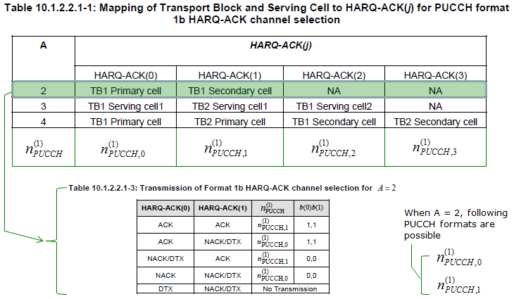
Note : What is meaning of NACK/DTX ?
It means NACK or DTX. For example, in case of fourth item.. Network can determine that UE has send explicit 'NACK' for PDSCH on PCC, but it cannot determine whether UE has sent explicit NACK or does not sent any NACK nor ACK for SCC.
Then you would ask why we use this kind of ambiguous expression ? It may be to reduce the number of combination. If we need to handle NACK and DTX separately in every cases, the number of raws (combination) in the above table should be longer. In that case, we may need more information bits which can cause additional overhead.
To make it even more complicated, you need to take into account the following statement as well to fully interpret the table. (Following statement is from 36.213 10.1.2.2 FDD HARQ-ACK procedures for more than one configured serving cell)
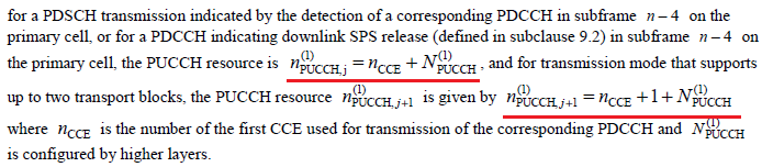
To understand the meaning of this table more clearly, let me give you an example case.
Let assume
i) sib2.radioResourceConfigCommon.pucch-ConfigCommon.n1PUCCH-AN = 0
ii) TPC Command for PUCCH = 00
iii)I am applying following case.
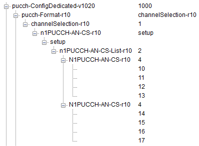
< Case 1 >
If HARQ-ACK(0) = ACK and HARQ-ACK(1) = ACK,
UE report (b(0)b(1) = (1,1)) via n1PUCCH= N1PUCCH-AN-CS-r10 = 10
< Case 2>
If HARQ-ACK(0) = ACK and HARQ-ACK(1) = NACK/DTX,
UE report (b(0)b(1) = (1,1)) via n1PUCCH = n1PUCCH-AN = (0 + n_CCE).
< Case 3>
If HARQ-ACK(0) = NACK/DTX and HARQ-ACK(1) = ACK,
UE report (b(0)b(1) = (0,0)) via n1PUCCH= N1PUCCH-AN-CS-r10 = 10.
< Case 4>
If HARQ-ACK(0) = NACK and HARQ-ACK(1) = NACK/DTX,
UE report (b(0)b(1) = (0,0)) via n1PUCCH= n1PUCCH-AN = (0 + n_CCE).
One important fact you would notice from this example is as follows :
Even though UE need to notify two PUCCH resources to report HARQ-ACK(0) and HARQ-ACK(1) if it wants to send it separately, by this way it can report about HARQ-ACK(0) and HARQ-ACK(1) using only one PUCCH resource
Example 1 > --------------------------------------------
Now let's see a more practical example as a practice to understand logic described above. Assume we tested in a following condition.
i) Carrier Aggregation 2 CC - SISO, NO DCI 0(UL Grant) to suppress PUSCH.
ii) sib2.radioResourceConfigCommon.pucch-ConfigCommon.n1PUCCH-AN = 0
iii) n_CCE = 14 (In reality, this would change subframe by subframe, but let's assume this is fixed)
iv) TPC Command for PUCCH = 00
v)I am applying following case.
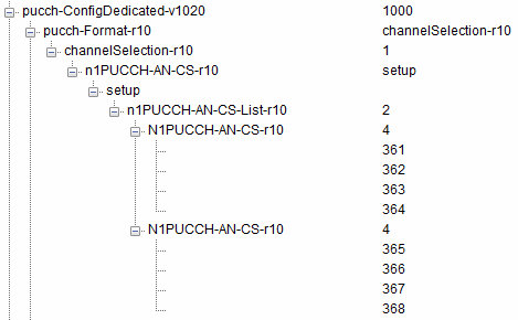
If Network received PUCCH as follows. How would interpret the result and fill out the cell (A)~(T)
|
Number |
Timing |
Recieved PUCCH |
Interpretation |
||||
|
SFN |
Subframe |
N1_PUCCH |
b(0) |
b(1) |
HARQ-ACK(0) |
HARQ-ACK(1) |
|
|
(1) |
814 |
4 |
361 |
0 |
0 |
(A) |
(B) |
|
(2) |
815 |
2 |
14 |
1 |
1 |
(C) |
(D) |
|
(3) |
694 |
4 |
361 |
0 |
0 |
(E) |
(F) |
|
(4) |
695 |
2 |
14 |
1 |
1 |
(G) |
(H) |
|
(5) |
174 |
4 |
361 |
0 |
0 |
(I) |
(J) |
|
(6) |
175 |
2 |
14 |
1 |
1 |
(K) |
(L) |
|
(7) |
674 |
5 |
361 |
1 |
1 |
(M) |
(N) |
|
(8) |
154 |
4 |
361 |
0 |
0 |
(O) |
(P) |
|
(9) |
155 |
2 |
14 |
1 |
1 |
(Q) |
(R) |
|
(10) |
658 |
4 |
361 |
0 |
0 |
(S) |
(T) |
If you filled out the cells as follows, it implies you understand the logic correctly. If not, read the logic described and try again.
|
Number |
Timing |
Recieved PUCCH |
Interpretation |
||||
|
SFN |
Subframe |
N1_PUCCH |
b(0) |
b(1) |
HARQ-ACK(0) |
HARQ-ACK(1) |
|
|
1 |
814 |
4 |
361 |
0 |
0 |
NACK/DTX |
ACK |
|
2 |
815 |
2 |
14 |
1 |
1 |
ACK |
NACK/DTX |
|
3 |
694 |
4 |
361 |
0 |
0 |
NACK/DTX |
ACK |
|
4 |
695 |
2 |
14 |
1 |
1 |
ACK |
NACK/DTX |
|
5 |
174 |
4 |
361 |
0 |
0 |
NACK/DTX |
ACK |
|
6 |
175 |
2 |
14 |
1 |
1 |
ACK |
NACK/DTX |
|
7 |
674 |
5 |
361 |
1 |
1 |
ACK |
ACK |
|
8 |
154 |
4 |
361 |
0 |
0 |
NACK/DTX |
ACK |
|
9 |
155 |
2 |
14 |
1 |
1 |
ACK |
NACK/DTX |
|
10 |
658 |
4 |
361 |
0 |
0 |
NACK/DTX |
ACK |
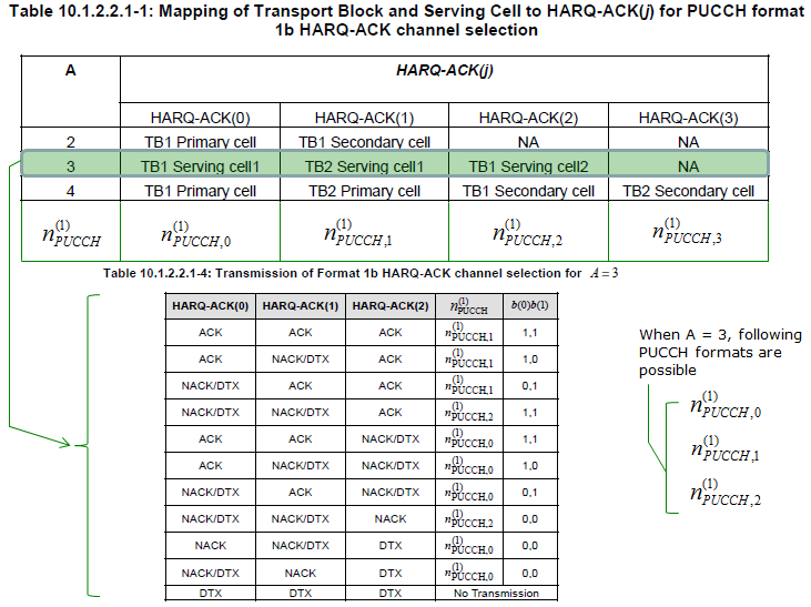
When A = 3
Three transport blocks give more combinations than four rows can hold, so the table below runs to eleven. Watch the right hand column while reading it, because three PUCCH resources are now in play rather than two.
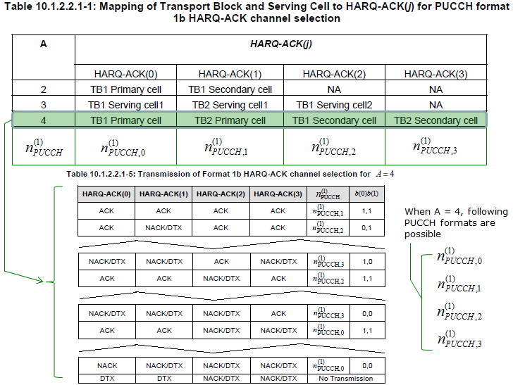
When A = 4
Four transport blocks are the largest case format 1b with channel selection handles, and all four PUCCH resources are used. The table below is drawn with gaps in it; the rows shown are the ones the page walks through immediately afterwards.
To make it even more complicated, you need to take into account the following statement as well to fully interpret the table. (Following statement is from 36.213 10.1.2.2 FDD HARQ-ACK procedures for more than one configured serving cell)
To understand the meaning of this table more clearly, let me give you an example case.
Let assume
i) sib2.radioResourceConfigCommon.pucch-ConfigCommon.n1PUCCH-AN = 0
ii) TPC Command for PUCCH = 00
iii)I am applying following case.
< Case 1 >
If HARQ-ACK(0) = ACK and HARQ-ACK(1) = ACK and HARQ-ACK(2) = ACK and HARQ-ACK(3) = ACK,
UE report (b(0)b(1) = (1,1)) via n1PUCCH = n1PUCCH-AN = (1 + n_CCE)
< Case 2>
If HARQ-ACK(0) = ACK and HARQ-ACK(1) = NACK/DTX and HARQ-ACK(2) = ACK and HARQ-ACK(3) = ACK,
UE report (b(0)b(1) = (0,1)) via n1PUCCH = N1PUCCH-AN-CS-r10 = 10.
< Case 3 >
If HARQ-ACK(0) = NACK/DTX and HARQ-ACK(1) = ACK and HARQ-ACK(2) = ACK and HARQ-ACK(3) = ACK,
UE report (b(0)b(1) = (0,1)) via n1PUCCH = n1PUCCH-AN = (1 + n_CCE)
< Case 4>
If HARQ-ACK(0) = NACK/DTX and HARQ-ACK(1) = NACK/DTX and HARQ-ACK(2) = ACK and HARQ-ACK(3) = ACK,
UE report (b(0)b(1) = (1,1)) via n1PUCCH = N1PUCCH-AN-CS-r10 = 14.
< Case 5 >
If HARQ-ACK(0) = ACK and HARQ-ACK(1) = ACK and HARQ-ACK(2) = ACK and HARQ-ACK(3) = NACK/DTX,
UE report (b(0)b(1) = (1,0)) via n1PUCCH = n1PUCCH-AN = (1 + n_CCE)
< Case 6>
If HARQ-ACK(0) = ACK and HARQ-ACK(1) = NACK/DTX and HARQ-ACK(2) = ACK and HARQ-ACK(3) = NACK/DTX,
UE report (b(0)b(1) = (0,0)) via n1PUCCH = N1PUCCH-AN-CS-r10 = 14.
< Case 7 >
If HARQ-ACK(0) = NACK/DTX and HARQ-ACK(1) = ACK and HARQ-ACK(2) = ACK and HARQ-ACK(3) = NACK/DTX,
UE report (b(0)b(1) = (0,0)) via n1PUCCH = n1PUCCH-AN = (1 + n_CCE)
< Case 8>
If HARQ-ACK(0) = NACK/DTX and HARQ-ACK(1) = NACK/DTX and HARQ-ACK(2) = ACK
and HARQ-ACK(3) = NACK/DTX,
UE report (b(0)b(1) = (1,0)) via n1PUCCH = N1PUCCH-AN-CS-r10 = 14.
< Case 9>
If HARQ-ACK(0) = ACK and HARQ-ACK(1) = ACK and HARQ-ACK(2) = NACK/DTX and HARQ-ACK(3) = ACK,
UE report (b(0)b(1) = (1,1)) via n1PUCCH = N1PUCCH-AN-CS-r10 = 10.
< Case 10>
If HARQ-ACK(0) = ACK and HARQ-ACK(1) = NACK/DTX and HARQ-ACK(2) = NACK/DTX and HARQ-ACK(3) = ACK,
UE report (b(0)b(1) = (1,0)) via n1PUCCH = N1PUCCH-AN-CS-r10 = 10.
< Case 11>
If HARQ-ACK(0) = NACK/DTX and HARQ-ACK(1) = ACK and HARQ-ACK(2) = NACK/DTX and HARQ-ACK(3) = ACK,
UE report (b(0)b(1) = (0,1)) via n1PUCCH = N1PUCCH-AN-CS-r10 = 14.
< Case 12>
If HARQ-ACK(0) = NACK/DTX and HARQ-ACK(1) = NACK/DTX and HARQ-ACK(2) = NACK/DTX
and HARQ-ACK(3) = ACK,
UE report (b(0)b(1) = (0,0)) via n1PUCCH = N1PUCCH-AN-CS-r10 = 14.
< Case 13 >
If HARQ-ACK(0) = ACK and HARQ-ACK(1) = ACK and HARQ-ACK(2) = NACK/DTX and HARQ-ACK(3) = NACK/DTX,
UE report (b(0)b(1) = (1,1)) via n1PUCCH = n1PUCCH-AN = (0 + n_CCE)
< Case 14 >
If HARQ-ACK(0) = ACK and HARQ-ACK(1) = NACK/DTX and HARQ-ACK(2) = NACK/DTX
and HARQ-ACK(3) = NACK/DTX,
UE report (b(0)b(1) = (1,0)) via n1PUCCH = n1PUCCH-AN = (0 + n_CCE)
< Case 15 >
If HARQ-ACK(0) = NACK/DTX and HARQ-ACK(1) = ACK and HARQ-ACK(2) = NACK/DTX
and HARQ-ACK(3) = NACK/DTX,
UE report (b(0)b(1) = (0,1)) via n1PUCCH = n1PUCCH-AN = (0 + n_CCE)
< Case 16 >
If HARQ-ACK(0) = NACK/DTX and HARQ-ACK(1) = NACK and HARQ-ACK(2) = NACK/DTX
and HARQ-ACK(3) = NACK/DTX,
UE report (b(0)b(1) = (0,0)) via n1PUCCH = n1PUCCH-AN = (0 + n_CCE)
< Case 17 >
If HARQ-ACK(0) = NACK and HARQ-ACK(1) = NACK/DTX and HARQ-ACK(2) = NACK/DTX
and HARQ-ACK(3) = NACK/DTX,
UE report (b(0)b(1) = (0,0)) via n1PUCCH = n1PUCCH-AN = (0 + n_CCE)
< Case 18 >
If HARQ-ACK(0) = DTX and HARQ-ACK(1) = DTX and HARQ-ACK(2) = NACK/DTX and HARQ-ACK(3) = NACK/DTX,
No Transmission
RRC Message Mapping - Format 1b
Format 1b can be configured in RRC message (RRC Connection Reconfiguration) as shown below. The three trees below are the same message read three times, each with a different part highlighted, so it is worth taking them together rather than one at a time.
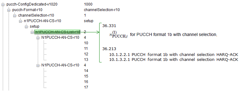
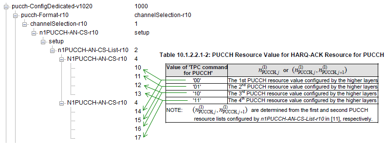
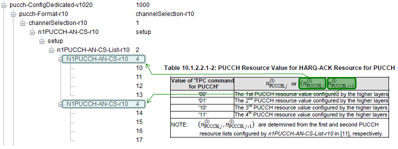
The structure those trees decode is short, and reading it explains the arrows. 36.331 puts the choice between the two carrier aggregation formats in one field, pucch-Format-r10, and gives each branch its own resource list.
Following is based on
PUCCH-ConfigDedicated-v1020 ::=     SEQUENCE {
    pucch-Format-r10                    CHOICE {
        format3-r10                     PUCCH-Format3-Conf-r13,
        channelSelection-r10                SEQUENCE {
            n1PUCCH-AN-CS-r10                   CHOICE {
                release                             NULL,
                setup                               SEQUENCE {
                    n1PUCCH-AN-CS-List-r10              SEQUENCE (SIZE (1..2)) OF N1PUCCH-AN-CS-r10
                }
            }                                                               OPTIONAL    -- Need ON
        }
    }                                                                       OPTIONAL,   -- Need OR
    twoAntennaPortActivatedPUCCH-Format1a1b-r10     ENUMERATED {true}       OPTIONAL,   -- Need OR
    simultaneousPUCCH-PUSCH-r10                     ENUMERATED {true}       OPTIONAL,   -- Need OR
    n1PUCCH-AN-RepP1-r10                            INTEGER (0..2047)       OPTIONAL    -- Need OR
}

N1PUCCH-AN-CS-r10   ::= SEQUENCE (SIZE (1..4)) OF INTEGER (0..2047)

PUCCH-Format3-Conf-r13 ::=  SEQUENCE {
    n3PUCCH-AN-List-r13 SEQUENCE (SIZE (1..4)) OF INTEGER (0..549)  OPTIONAL,   -- Need ON
    twoAntennaPortActivatedPUCCH-Format3-r13        CHOICE {
        release                                         NULL,
        setup                                           SEQUENCE {
            n3PUCCH-AN-ListP1-r13   SEQUENCE (SIZE (1..4)) OF INTEGER (0..549)
        }
    }                                                               OPTIONAL    -- Need ON
}
Three sizes in that listing match the trees above exactly. N1PUCCH-AN-CS-r10 is a list of one to four integers, which is the four values each branch of the tree shows. n1PUCCH-AN-CS-List-r10 holds one or two of those lists, which is the pair of N1PUCCH-AN-CS-r10 entries the tree draws. The values run 0 to 2047, and the ones in the trees are 10 to 17 in one capture and 361 to 368 in the other.
The two lists are not alternatives. 36.213 Table 10.1.2.2.1-2 is reproduced in the tree above, and its note says the first and second resource lists give the resources for j and for j plus one. So the first list serves the first transport block and the second serves the second, which is why a UE with two transport blocks on a cell needs both.
Within one list the four values are selected by the DCI. The same table maps the TPC command field of the secondary cell grant, values 00 to 11, onto the first, second, third and fourth value the higher layers configured. The TPC field is doing two jobs on a secondary cell: it is a power command on the primary cell and a resource pointer here.
One name in the trees is out of date rather than wrong. The captures show n3PUCCH-AN-List-r10, and 36.331 v19.3.0 no longer defines that field. The format3-r10 branch now points at PUCCH-Format3-Conf-r13, whose list is n3PUCCH-AN-List-r13 and whose values run 0 to 549 rather than 0 to 2047. Release 13 rewrote the type without renaming the branch that reaches it.
The choice is one field : pucch-Format-r10 selects channelSelection-r10 or format3-r10, and nothing configures both.Four values per list : N1PUCCH-AN-CS-r10 is SIZE (1..4), which is the four rows of 36.213 Table 10.1.2.2.1-2.Two lists, one per transport block : the first gives the resource for j and the second the resource for j plus one.The TPC field picks one of the four : values 00 to 11 select the first to fourth configured resource value on a secondary cell grant.The format 3 list was retyped in Release 13 : n3PUCCH-AN-List-r13 replaced the r10 field, and its range narrowed to 0 to 549.
Format 3
Up to 2 CC CA we could handle HARQ Ack/Nack process with Format1b but as you saw in previous section it was super complicated / confusing to understand (I think it is because we have to implement HARQ process for 2 CC with a format which does not have enough number of bits to use. So they needed to use such a strange looking tricks). From 3CC CA, whatever trick you use it would be impossible to handle more than 3CC with format1b, so we need to use PUCCH format which has much larger number of bits in it. It is PUCCH Format 3. However, the way it works is much simpler (at least much simpler to understand). It can have max 11 bits in FDD (21 bits in TDD) for HARQ Ack/Nack that can cover max 5 CC with 2 Codewords and some additional bit for CSI report. In terms of HARQ, it is very simple... just map each bits of the 20 possible bits to each CC (Component Carrier) and each Antenna (if it is MIMO). Overall operation is described as follows in 36.213 10.1.2.2.2 PUCCH format 3 HARQ-ACK procedure.
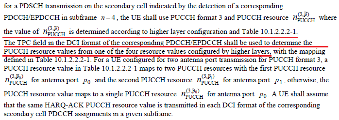
The way you configure PUCCH format 3 in terms of Carrier Aggregation is as follows. Each of the items in n3PUCCH determines the final location of PUCCH on frequency domain at physical subframe (Refer to PUCCH Format 3 page regarding how this parameter determines the physical location of the PUCCH). UE will apply only one parameter of the four values in the RRC message at a specific subframe. Then, how UE can figure out which value to use at each subframe ? It is instructed by eNB via TPC field in DCI as indicated below.
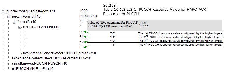
The arrangement is the same shape as format 1b and the numbers are different. Four values are configured, the TPC field of a secondary cell grant selects one of them, and the tree above shows the four as 60 to 63 under n3PUCCH-AN-List. What changes is that the selected resource carries the whole HARQ-ACK payload, rather than standing in for part of it.
That is why format 3 is counted in bits while format 1b is counted in cells. 36.213 clause 10.1.1 gives format 3 up to 10-bit HARQ-ACK for FDD and up to 20-bit for TDD. Ten bits is five cells at two transport blocks each, or ten cells at one bit each, and Release 13 added the field that chooses between those two readings.
The field is spatialBundlingPUCCH, a BOOLEAN in PUCCH-ConfigDedicated-r13. 36.331 describes it as indicating whether spatial bundling is enabled for PUCCH. With it enabled the two transport blocks of a cell are combined into one bit, so the same ten bits reach twice as many cells. That is the mechanism behind the five and ten carrier figures quoted at the top of this page.
Four resources, one DCI field : n3PUCCH-AN-List holds up to four values and the TPC command field selects among them, exactly as for format 1b.Format 3 is measured in bits : up to 10-bit HARQ-ACK for FDD and up to 20-bit for TDD, per 36.213 clause 10.1.1.Bits become cells through spatial bundling : spatialBundlingPUCCH collapses the two transport blocks of a cell into one bit.Two antenna ports need a second list : twoAntennaPortActivatedPUCCH-Format3 adds n3PUCCH-AN-ListP1, a second list of the same size.
Which PUCCH format to use ?
This question is still a challenging one to me. In Carrier Aggregation Condition, it is obvious that we can use PUCCH format1b or PUCCH format 3. However, the tricky thing is to figure out which of the two we need to use.
The most important factors to determine the format is the number of ACK bits required for the specified cell configuration. To understand each and every details of the PUCCH format determination, you would need to understand every single line of following sections in 36.213.
- 10.1.2.2 FDD HARQ-ACK procedures for more than one configured serving cell
- 10.1.3.2 TDD HARQ-ACK procedure for more than one configured serving cell
Following is a summary of format selection based on my experience and the test equipment/UE that I have used. However, I don't think this is the only possible configuration. I will keep adding to the table as I try more.
|
Duplex Mode |
Case |
PUCCH Format |
|
FDD |
2CC CA - lower than Category 9 |
PUCCH Format1b (NOTE 1) |
|
2CC CA - higher than Category 9 |
PUCCH Format3 (NOTE 2) |
|
|
More than 3CC CA |
PUCCH Format3 (NOTE 3) |
|
|
TDD |
2CC CA (Except Subframe Config 5) |
PUCCH Format1b (NOTE 4) |
|
2CC CA - Subframe Config 5 |
PUCCH Format3 (NOTE 5) |
|
|
FDD-TDD |
2CC CA - (Primary :FDD, Secondary : TDD) |
PUCCH Format1b (NOTE 6) |
NOTE 1,3 :
Following is from 36.213 10.1.2.2.
HARQ-ACK transmission on two antenna ports ( p∈[ p0, p1]) is supported for PUCCH format 3.
HARQ-ACK transmission on two antenna ports ( p∈[ p0, p1]) is supported for PUCCH format 1b with channel selection and FDD with two configured serving cells.
Following is from 36.213 10.1.2
For FDD and for a UE transmitting HARQ-ACK using PUCCH format 1b with channel selection or PUCCH format 3, the UE shall determine the number of HARQ-ACK bits, O , based on the number of configured serving cells and the downlink transmission modes configured for each serving cell. The UE shall use two HARQ-ACK bits for a serving cell configured with a downlink transmission mode that support up to two transport blocks; and one HARQ-ACK bit otherwise.
NOTE 4 :
Following is from 36.213 10.1.3.2.2 PUCCH format 3 HARQ-ACK procedure
- for M > 1, and
- for M = 9 <-- M = 9 is for subframe configuration 5. Refer to M definition of LTE-TDD Overview page
the UE shall use PUCCH format 3
NOTE 6 : Refer to 36.213 10.1.2A FDD-TDD HARQ-ACK feedback procedures for primary cell frame structure type 1
A UE that supports aggregating at most 2 serving cells shall use PUCCH format 1b with channel selection for transmission of HARQ-ACK when configured with primary cell frame structure type 1 and secondary cell frame structure type 2.
PUCCH format 4 and format 5
The table above summarises one engineer's experience with the equipment available at the time, and it stops at format 3. Release 13 raised the ceiling on serving cells from 5 to 32, and 36.331 still carries both numbers as maxServCell-r10 and maxServCell-r13. Twenty bits of HARQ-ACK cannot cover 32 cells however they are bundled. Two more formats answer it, and both are already named in the Release 13 and 14 extract at the top of this page.
The dividing line is a bit count rather than a cell count. 36.213 clause 10.1.1 gives format 4 and format 5 to more than 22 bits of UCI including HARQ-ACK, SR if any, and periodic CSI reports if any. The same clause caps format 3 at 22 bits for a UE that has format 4 or format 5 configured, so the three do not overlap.
36.331 carries the configuration in a new element rather than another suffix on the old one. PUCCH-ConfigDedicated-r13 restates everything from Release 8 onwards, and its pucch-Format-r13 is a four way CHOICE instead of the two way one above.
Following is based on
PUCCH-ConfigDedicated-r13 ::=       SEQUENCE {
--Release 8
    ackNackRepetition-r13               CHOICE{
        release                             NULL,
        setup                               SEQUENCE {
            repetitionFactor-r13                ENUMERATED {n2, n4, n6, spare1},
            n1PUCCH-AN-Rep-r13              INTEGER (0..2047)
        }
    },
    tdd-AckNackFeedbackMode-r13         ENUMERATED {bundling, multiplexing} OPTIONAL,   -- Cond TDD
--Release 10
    pucch-Format-r13                    CHOICE {
        format3-r13                             SEQUENCE {
            n3PUCCH-AN-List-r13 SEQUENCE (SIZE (1..4)) OF INTEGER (0..549)  OPTIONAL,   -- Need ON
            twoAntennaPortActivatedPUCCH-Format3-r13        CHOICE {
                release                                         NULL,
                setup                                           SEQUENCE {
                    n3PUCCH-AN-ListP1-r13   SEQUENCE (SIZE (1..4)) OF INTEGER (0..549)
                }
            }                                                               OPTIONAL    -- Need ON
        },
        channelSelection-r13                SEQUENCE {
            n1PUCCH-AN-CS-r13                   CHOICE {
                release                             NULL,
                setup                               SEQUENCE {
                    n1PUCCH-AN-CS-List-r13              SEQUENCE (SIZE (1..2)) OF N1PUCCH-AN-CS-r10,
                    dummy1          SEQUENCE (SIZE (2..4)) OF INTEGER (0..2047)
                }
            }                                                               OPTIONAL    -- Need ON
        },
        format4-r13                         SEQUENCE {
            format4-resourceConfiguration-r13           SEQUENCE (SIZE (4)) OF Format4-resource-r13,
            format4-MultiCSI-resourceConfiguration-r13  SEQUENCE (SIZE (1..2)) OF Format4-resource-r13 OPTIONAL -- Need OR
        },
        format5-r13             SEQUENCE {
            format5-resourceConfiguration-r13           SEQUENCE (SIZE (4)) OF Format5-resource-r13,
            format5-MultiCSI-resourceConfiguration-r13  Format5-resource-r13 OPTIONAL   -- Need OR
        }
    }                                                                       OPTIONAL,   -- Need OR
    twoAntennaPortActivatedPUCCH-Format1a1b-r13     ENUMERATED {true}       OPTIONAL,   -- Need OR
    simultaneousPUCCH-PUSCH-r13                     ENUMERATED {true}       OPTIONAL,   -- Need OR
    n1PUCCH-AN-RepP1-r13                            INTEGER (0..2047)       OPTIONAL,   -- Need OR
--Release 11
    nPUCCH-Param-r13                    CHOICE {
        release                             NULL,
        setup                               SEQUENCE {
            nPUCCH-Identity-r13                 INTEGER (0..503),
            n1PUCCH-AN-r13                      INTEGER (0..2047)
        }
    }                                                                       OPTIONAL,   -- Need ON
--Release 12
    nkaPUCCH-Param-r13                  CHOICE {
        release                             NULL,
        setup                               SEQUENCE {
            nkaPUCCH-AN-r13                     INTEGER (0..2047)
        }
    }                                                                       OPTIONAL,   -- Need ON
--Release 13
    spatialBundlingPUCCH-r13            BOOLEAN,
    spatialBundlingPUSCH-r13            BOOLEAN,
    harq-TimingTDD-r13                  BOOLEAN,
    codebooksizeDetermination-r13       ENUMERATED {dai,cc}                 OPTIONAL,   -- Need OR
    maximumPayloadCoderate-r13          INTEGER (0..7)                      OPTIONAL,   -- Need OR
    pucch-NumRepetitionCE-r13           CHOICE {
        release                     NULL,
        setup                       CHOICE {
            modeA                       SEQUENCE {
                pucch-NumRepetitionCE-format1-r13                   ENUMERATED {r1, r2, r4, r8},
                pucch-NumRepetitionCE-format2-r13                   ENUMERATED {r1, r2, r4, r8}
            },
            modeB                       SEQUENCE {
                pucch-NumRepetitionCE-format1-r13                   ENUMERATED {r4, r8, r16, r32},
                pucch-NumRepetitionCE-format2-r13                   ENUMERATED {r4, r8, r16, r32}
            }
        }
    }                                                                       OPTIONAL    --Need ON
}

Format4-resource-r13    ::=             SEQUENCE {
    startingPRB-format4-r13                     INTEGER (0..109),
    numberOfPRB-format4-r13                 INTEGER (0..7)
}

Format5-resource-r13    ::=             SEQUENCE {
    startingPRB-format5-r13                     INTEGER (0..109),
    cdm-index-format5-r13                       INTEGER (0..1)
}
The two resource types say what separates format 4 from format 5, in four fields. Format4-resource carries a starting PRB and a number of PRBs. Format5-resource carries a starting PRB and a CDM index of 0 or 1. So format 4 buys capacity with bandwidth and format 5 shares one allocation between two UEs.
36.211 confirms the split at the symbol level. Clause 5.4.2B takes the QPSK symbols of format 4 straight into transform precoding, over a bandwidth given in resource blocks. Clause 5.4.2C applies block-wise spreading to format 5 first, with the orthogonal sequence chosen by a parameter from higher layers, and only then transform precodes. The CDM index is that parameter.
Both branches configure four resources and an optional extra. format4-resourceConfiguration is SEQUENCE (SIZE (4)), so the TPC selection that runs through this whole page applies here too. The MultiCSI entries beside them are for the case 36.213 lists separately, where the report carries more than one CSI report rather than HARQ-ACK.
One more Release 13 field decides how long the HARQ-ACK codebook is before any of this matters. codebooksizeDetermination takes the value dai or cc, and 36.331 describes it as choosing whether the codebook size follows the downlink assignment indicator or the number of configured component carriers. With 32 cells configured the difference between those two is most of the payload.
More than 22 bits is the trigger : 36.213 clause 10.1.1 gives formats 4 and 5 that range and caps format 3 at 22 bits when either is configured.Format 4 grows the allocation : Format4-resource carries a starting PRB and a number of PRBs from 0 to 7.Format 5 shares one allocation : Format5-resource carries a starting PRB and a CDM index of 0 or 1, and 36.211 clause 5.4.2C spreads the symbols before precoding them.The four resource selection is unchanged : both branches configure exactly four resources, selected the same way as for formats 1b and 3.Release 13 also chose a codebook rule : codebooksizeDetermination is dai or cc, and with 32 cells that choice sets most of the payload size.Short TTI narrowed the choice again : 36.213 v19.4.0 allows only formats 1, 1a, 1b, 3 and 4 on slot-PUCCH, and only 1, 1a, 1b and 4 on subslot-PUCCH.
Reference
Three specifications carry everything quoted on this page. 36.213 lists which format carries what. 36.331 defines the resources each format is given. 36.211 says what the physical layer does with them.
- [1] 36.213 : 3GPP - E-UTRA; Physical layer procedures, v19.4.0. Clause 10.1.1 is the format list shown at the top of this page, and clauses 10.1.2.2 and 10.1.3.2 hold the channel selection tables.
- [2] 36.331 : 3GPP - E-UTRA; Radio Resource Control, v19.3.0. PUCCH-ConfigDedicated-v1020 and PUCCH-ConfigDedicated-r13 are quoted above.
- [3] 36.211 : 3GPP - E-UTRA; Physical channels and modulation, v19.3.0. Clauses 5.4.2B and 5.4.2C define PUCCH format 4 and format 5.