LTE TDD uses the same 10 ms radio frame and 1 ms subframe as FDD. The difference is that downlink and uplink share one carrier, so each subframe belongs to one direction at a time. That single decision changes almost every timing rule of the physical layer. The table below compares the two duplex modes feature by feature, and each feature links to its section on this page.
|
Features |
FDD |
TDD |
|
10 ms radio frame, 1 ms sub frame |
10 ms radio frame, 1 ms sub frame |
|
|
N/A |
5 ms or 10 ms periodicity |
|
|
DL Control Channel |
Can Schedule 1 DL and 1 UL subframe at a time |
Can schedule 1 DL and multiple UL sub-frame at a time |
|
UL Control Channel |
Single Ack/Nack corresponding to 1DLsub frame |
Ack/Nack corresponding to multiple DL sub frame |
|
0,1,2,3 |
0,1,2,3,4(Short RACH) |
|
|
|
|
|
|
N/A |
DwPTS : RS, Data and Control UpPTS : SRS and Short RACH |
|
|
K = 4 (fixed) DL : Async, UL :Sync |
K = varying depending on Subframe Config DL : Async, UL : Sync |
|
One Transmission one Ack/Nack |
Bundling or Multiplexed |
|
4 ms |
Varying |
|
4 ms |
Varying |
|
|
|
SIB1 |
Most rows of the table come back to one idea. In FDD every procedure can use a fixed delay of 4 subframes, because an uplink subframe always exists 4 ms later. In TDD that subframe may be a downlink subframe. So each fixed delay of FDD becomes a lookup table in TDD, indexed by the UL/DL configuration.
- Frame Structure
- Switching Points
- PRACH Preamble Format
- RACH Configuration
- Special Slot Usage
- HARQ Timing
- SR/DCI 0 Timing
- DCI 0/PUSCH Timing
- Issues with Debugging
- Ack/Nack Feedback Mode
- System Information Variation
- Reference
Frame Structure
A TDD cell has to tell the UE two things about its frame. The first is which subframes are downlink, uplink or special. The second is how the special subframe is divided into a downlink part, a guard period and an uplink part. The two blocks below cover these settings in that order.
Subframe UL/DL Configuration
36.211 Table 4.2-2 defines seven UL/DL configurations, numbered 0 to 6. Subframes 0 and 5 are always downlink, subframe 1 is always special and subframe 2 is always uplink. Only the other subframes change from one configuration to the next.
The diagram below puts Table 4.2-2 on top of one radio frame. The clouds say which subframes are fixed and which ones follow the configuration, and the lower part shows how the special subframe is split.
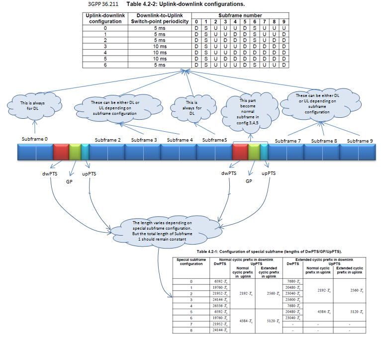
- Subframe 0 and Subframe5 : always downlink in every configuration.
- Subframe 1 : always a special subframe with dwPTS, GP and upPTS. The PSS is in the third OFDM symbol of subframes 1 and 6, so it sits in the DwPTS.
- Subframe 6 : a special subframe in configurations 0, 1, 2 and 6, and a normal downlink subframe in configurations 3, 4 and 5, as the cloud in the middle says.
- Subframes 2, 3, 4, 7, 8 and 9 : downlink or uplink depending on the configuration. Subframe 2 is uplink in all seven rows.
- Lower cloud : the lengths of DwPTS, GP and UpPTS vary with the special subframe configuration, but the total length of the special subframe stays at 1 ms. The Table 4.2-1 excerpt below it lists configurations 0 to 8.
Special Subframe Length
The special subframe is where the cell switches from downlink to uplink. Its guard period has to cover the round trip delay to the cell edge and the switching time of the radios. So a larger cell needs a longer GP, and it pays for the GP with a shorter DwPTS.
The table below lists configurations 0 to 8 for normal cyclic prefix in both directions. The UpPTS column holds the normal CP values of 36.211 Table 4.2-1: 2192 Ts for one symbol and 4384 Ts for two symbols. The extended uplink CP would give 2560 Ts and 5120 Ts.
|
Special Subframe Configuration |
Length in Samples (Normal CP) |
Length in OFDM Symbols (Normal CP) |
||||
|
DwPTS |
GP |
UpPTS |
DwPTS |
GP |
UpPTS |
|
|
0 |
6592 Ts |
|
2192 Ts |
3 |
10 |
1 |
|
1 |
19760 Ts |
|
2192 Ts |
9 |
4 |
1 |
|
2 |
21952 Ts |
|
2192 Ts |
10 |
3 |
1 |
|
3 |
24144 Ts |
|
2192 Ts |
11 |
2 |
1 |
|
4 |
26336 Ts |
|
2192 Ts |
12 |
1 |
1 |
|
5 |
6592 Ts |
|
4384 Ts |
3 |
9 |
2 |
|
6 |
19760 Ts |
|
4384 Ts |
9 |
3 |
2 |
|
7 |
21952 Ts |
|
4384 Ts |
10 |
2 |
2 |
|
8 |
24144 Ts |
|
4384 Ts |
11 |
1 |
2 |
Read the table with its units in mind. Ts is 1/30720 ms, so one subframe is 30720 Ts. A normal CP symbol is 2192 Ts, except the first symbol of each slot, which is 2208 Ts. So DwPTS of 6592 Ts is 3 symbols. The GP in samples is what remains of 30720 Ts after DwPTS and UpPTS. For configuration 0 that is 30720 - 6592 - 2192 = 21936 Ts, about 714 microseconds.
The current 36.211 v19.3.0 has more rows than this table. Configuration 9 has a DwPTS of 13168 Ts, which is 6 symbols, so its GP is 6 symbols and its UpPTS 2 symbols. Configuration 10 came with Release 14. Higher layers can also add X extra SC-FDMA symbols to UpPTS with srs-UpPtsAdd, which makes UpPTS (1+X) or (2+X) symbols long.
For the examples of TDD resource grids for each Subframe DL/UL Configuration and Special Subframe Configuration, see Frame Structure Frame Type 2 Overview section.
Subframes 0, 1, 2 and 5 never change : subframes 0 and 5 are downlink, subframe 1 is special and subframe 2 is uplink.The UL/DL configuration sets the direction : 36.211 Table 4.2-2 defines configurations 0 to 6.The special subframe configuration sets the split : DwPTS, GP and UpPTS always add up to 30720 Ts.The GP sets the cell size : a longer GP covers a longer round trip, at the cost of DwPTS.
Switching Points
Every change from downlink to uplink needs a guard period, and the guard period lives in the special subframe. So the number of special subframes per frame decides how often the cell can switch direction. 36.211 calls this interval the downlink-to-uplink switch-point periodicity, and it is either 5 ms or 10 ms.
The diagram below shows two frames, SFN (N) and SFN (N+1), for all seven configurations. The green boxes mark the special subframes of configuration 0 and configuration 5, and the arrows measure the distance between them.
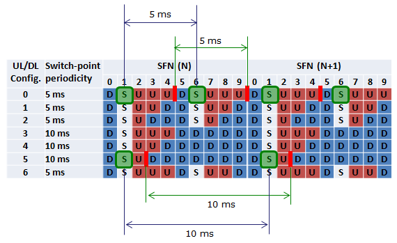
- Configuration 0 : special subframes in subframes 1 and 6, so the distance between two switch points is 5 ms.
- Configuration 5 : subframe 6 is a downlink subframe, so the next special subframe is subframe 1 of the next frame, 10 ms later.
- Switch-point periodicity column : 5 ms for configurations 0, 1, 2 and 6, and 10 ms for configurations 3, 4 and 5.
- Red bars : they mark the change from uplink back to downlink. That change happens between two normal subframes, with no special subframe in between.
So the choice of configuration is a choice between two costs. A 5 ms configuration has two special subframes per frame and loses more time to guard periods. A 10 ms configuration has one special subframe, but an uplink packet may wait longer for its next uplink subframe.
Only the downlink-to-uplink switch needs a special subframe : the change from uplink to downlink needs no guard period in the frame.5 ms periodicity means two special subframes per frame : configurations 0, 1, 2 and 6 use subframe 6 as a second special subframe.10 ms periodicity trades latency for capacity : configurations 3, 4 and 5 turn subframe 6 into a downlink subframe.
PRACH Preamble Format
A PRACH preamble has to fit into the uplink time that the frame offers. In FDD every subframe can be uplink, but in TDD a long preamble competes with a few uplink subframes. So TDD adds a very short format that fits into the UpPTS of the special subframe.
Refer to 36.211 5.7 Physical random access channel for the details.
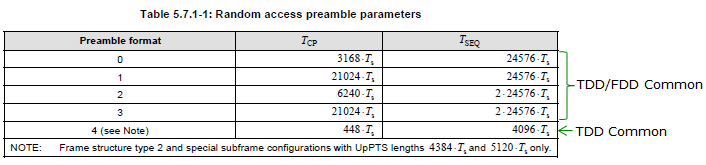
- Formats 0 to 3 : common to TDD and FDD. They differ in the cyclic prefix TCP and the sequence length TSEQ, from 3168 Ts plus 24576 Ts for format 0 up to 21024 Ts plus 2 x 24576 Ts for format 3.
- Format 4 : TDD only, with a 448 Ts cyclic prefix and a 4096 Ts sequence.
- NOTE : format 4 is used only in frame structure type 2 and only with special subframe configurations whose UpPTS is 4384 Ts or 5120 Ts, which is the two symbol UpPTS.
Format 4 is short in every dimension. It uses a Zadoff-Chu sequence of length 139 instead of 839, and a subcarrier spacing of 7500 Hz instead of 1250 Hz, following 36.211 Table 5.7.2-1 and Table 5.7.3-1. So it covers only a small cell, but it costs no uplink subframe.
Formats 0 to 3 are shared with FDD : they occupy one or more normal uplink subframes.Format 4 lives in UpPTS : it needs a special subframe configuration with a two symbol UpPTS.Format 4 uses a 139 long sequence at 7500 Hz : the short preamble limits the cell radius.
RACH Configuration
The PRACH configuration index tells the UE which preamble format to use and where the PRACH occasions are. FDD needs only a subframe number for that. TDD also needs to know how many occasions exist per frame, because the number of uplink subframes changes with the UL/DL configuration.
36.211 Table 5.7.1-3 below maps each PRACH configuration index to three values. These are the preamble format, the density DRA of PRACH occasions per 10 ms, and the version rRA.
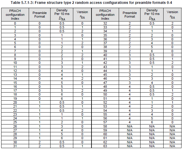
- Indexes 0 to 19 : preamble format 0, with densities from 0.5 to 6 per 10 ms.
- Indexes 20 to 29 : format 1, and indexes 30 to 39 : format 2.
- Indexes 40 to 47 : format 3, and indexes 48 to 57 : format 4.
- Indexes 58 to 63 : N/A.
- A density of 0.5 means one PRACH occasion every 20 ms. The version rRA separates configurations with the same density, so that two cells with the same density can use different occasions.
The table gives only the density, not the exact subframe. 36.211 Table 5.7.1-4 turns each pair of DRA and rRA into one or more quadruples for each UL/DL configuration. Each quadruple gives a frequency resource index, the radio frames, the half frame and the uplink subframe of one PRACH resource. So TDD can place several PRACH resources in one subframe, separated in frequency, when the frame has few uplink subframes.
The index sets format, density and version : 36.211 Table 5.7.1-3 is the TDD version of the FDD Table 5.7.1-2.The exact position comes from Table 5.7.1-4 : it depends on the UL/DL configuration as well as on the index.TDD can stack PRACH in frequency : several PRACH resources can share one uplink subframe.
Special Slot Usage
The special subframe is not only a guard period. DwPTS behaves like a short downlink subframe and UpPTS like a very short uplink subframe, as the overview table says. The question is how much of each part the cell can use for data.
RB Allocation on Special Subframe
DwPTS is shorter than a normal subframe, so the same number of PRBs carries fewer resource elements. The UE therefore looks up the transport block size with a reduced PRB number, and the reduction depends on the special subframe configuration.
Refer to 36.213 7.1.7 Modulation order and transport block size determination for the details.
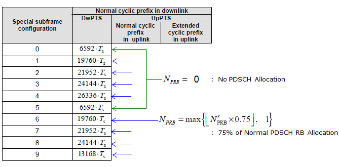
- Configurations 0 and 5 : DwPTS is only 6592 Ts, 3 symbols, so there is no PDSCH allocation. NPRB = 0.
- Configurations 1 to 4 and 6 to 9 : the UE uses NPRB = max{floor(N'PRB x 0.75), 1}, which is 75% of the normal PDSCH RB allocation, for the TBS lookup.
- The drawing groups configuration 9 with the 0.75 rule.
The current 36.213 v19.4.0 treats configuration 9 differently. For configurations 9 and 10 with normal cyclic prefix, clause 7.1.7 uses a factor of 0.375 instead of 0.75. So the drawing matches the earlier release for configuration 9, and a UE on a current release scales its TBS by 0.375 there.
UpPTS carries no PDSCH, and in the original design it carries only SRS and the short format 4 PRACH. Release 14 added PUSCH in UpPTS with symPUSCH-UpPts-r14.
DwPTS carries data with a scaled TBS : N'PRB is reduced to 75% for most configurations.Configurations 0 and 5 carry no PDSCH in DwPTS : their DwPTS is only 3 symbols.Configurations 9 and 10 use 0.375 today : 36.213 v19.4.0 clause 7.1.7 lowers the factor for them.UpPTS is for SRS and PRACH format 4 : PUSCH in UpPTS needs the Release 14 option.
HARQ Timing
In case of FDD, it is pretty simple and obvious for UE to transmit HARQ ACK or NACK. UE start preparing the response as soon as it completes the decoding PDSCH and transmit it 4 ms (4 TTI) later. But in TDD, UE cannot transmit the response in such a fixed timing as in FDD. It has to wait until it gets the next chance for UL transmission and the next chance will be different depending on UL/DL configuration. Even when UE gets the chance to transmit the UL, it is may not always possible to transmit all the necessary response. For example, if UE gets too many DL subframe before the UL subframe, it will be difficult to transmit the all the reply in the UL transmission because PUCCH space is not big enough to accomodate all the HARQ ACK/NACK. So they came out with very complicated/confusing table as shown below to define HARQ response to cope with this kind of situation. In this section, I will explain how to interpret this table and figure out the exact HARQ response timing for each UL/DL configuration.
ACK/NACK from UE for PDSCH
Let's start with the downlink data. The UE sends the HARQ-ACK in uplink subframe n, and 36.213 Table 10.1.3.1-1 lists for each n a set K of offsets k. Each PDSCH that the ACK/NACK covers is in subframe n - k.
Following table shows the Ack/Nack Transmission Timing from UE for the PDSCH it recieved.
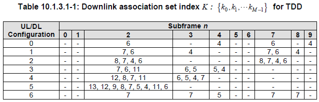
Problem is how to interpret this table. Following shows how to interpret each raw of the table.
Case 1 : UL/DL Configuration 0
In case of UL/DL Configuration 0, Ack/Nack response timing for the PDSCH that is received by UE is transmitted according to the following rule.
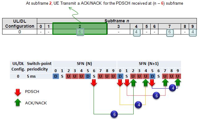
How do you interpret this table and DL/UL correlation ?
It says
- UE transmit Ack/Nack at subframe 2,4,7,9
- At subframe 2, UE transmit Ack/Nack for PDSCH it received at subframe 6 in previous SFN
- At subframe 4, UE transmit Ack/Nack for PDSCH it received at subframe 0 in current SFN
- At subframe 7, UE transmit Ack/Nack for PDSCH it received at subframe 1 in current SFN
- At subframe 9, UE transmit Ack/Nack for PDSCH it received at subframe 5 in current SFN
Case 2 : UL/DL Configuration 1
In case of UL/DL Configuration 1, Ack/Nack response timing for the PDSCH that is received by UE is transmitted according to the following rule.

How do you interpret this table and DL/UL correlation ?
It says
- UE transmit Ack/Nack at subframe 2,3,7,8
- At subframe 2, UE transmit Ack/Nack for PDSCH it received at subframe 5,6 in previous SFN
- At subframe 3, UE transmit Ack/Nack for PDSCH it received at subframe 9 in previous SFN
- At subframe 7, UE transmit Ack/Nack for PDSCH it received at subframe 0,1 in current SFN
- At subframe 8, UE transmit Ack/Nack for PDSCH it received at subframe 4 in current SFN
Case 3 : UL/DL Configuration 2
In case of UL/DL Configuration 2, Ack/Nack response timing for the PDSCH that is received by UE is transmitted according to the following rule.
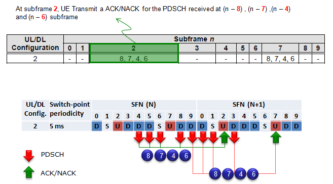
How do you interpret this table and DL/UL correlation ?
It says
- UE transmit Ack/Nack at subframe 2,7
- At subframe 2, UE transmit Ack/Nack for PDSCH it received at subframe 4,5,6,8 in previous SFN
- At subframe 7, UE transmit Ack/Nack for PDSCH it received at subframe 9 in previous SFN and 0,1,3 in current SFN
Please try to do the same analysis for the remaining UL/DL Configuration on your own. It would be the best way for you to understand the meaning of the table clearly.
Two patterns hold in every row. The smallest k in the table is 4, so the UE always has at least the 4 ms processing time of FDD. And the number of elements in K, which 36.213 calls M, grows with the number of downlink subframes. It reaches 9 in configuration 5, where subframe 2 is the only uplink subframe that carries HARQ-ACK.
ACK/NACK from eNB for PUSCH
The uplink direction has the mirror problem. The eNB answers each PUSCH on PHICH, and the PHICH has to wait for a downlink subframe or a DwPTS. 36.213 Table 9.1.2-1 gives kPHICH, so a PUSCH in subframe n gets its PHICH in subframe n + kPHICH.
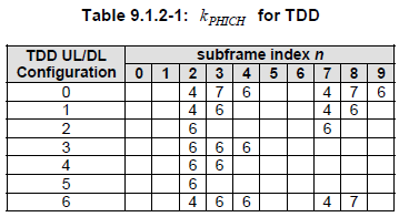
Case 1 : UL/DL Configuration 0
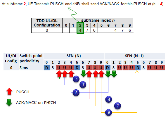
It says
- PUSCH in subframe 2 gets its PHICH in subframe 6, the special subframe of the same SFN, with k = 4
- PUSCH in subframes 3 and 4 gets its PHICH in subframe 0 of the next SFN, with k = 7 and k = 6
- PUSCH in subframe 7 gets its PHICH in subframe 1 of the next SFN, with k = 4
- PUSCH in subframes 8 and 9 gets its PHICH in subframe 5 of the next SFN, with k = 7 and k = 6
Case 2 : UL/DL Configuration 1
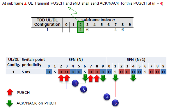
It says
- PUSCH in subframes 2 and 3 gets its PHICH in subframes 6 and 9 of the same SFN, with k = 4 and k = 6
- PUSCH in subframes 7 and 8 gets its PHICH in subframes 1 and 4 of the next SFN, with k = 4 and k = 6
Notice that configuration 0 has six uplink subframes but only four downlink or special subframes per frame. Two PUSCH transmissions must therefore share one PHICH subframe, and 36.213 separates them with the IPHICH index of the PHICH resource.
The UE answers PDSCH in subframe n for subframes n - k : K comes from 36.213 Table 10.1.3.1-1.The eNB answers PUSCH in subframe n + kPHICH : kPHICH comes from 36.213 Table 9.1.2-1.k is never less than 4 : TDD keeps the FDD processing time and only adds waiting time.M is the size of the set K : it tells how many downlink subframes one uplink subframe answers.
SR/DCI 0 Timing
The Time delay between SR(Scheduling Request) and DCI 0 is not clearly specified in 3GPP specification. So basically, NW can send DCI 0 in any available DL subframe after reception of SR, but depending on the eNodeB and Test Equipment some minimum time interval may be required.
TDD still limits the SR itself. 36.213 clause 10.1.5 allows SR transmission instances only in uplink subframes, so the SR configuration has to land on an uplink subframe of the UL/DL configuration. The whole path from SR to data then has three waits. The UE waits for its SR occasion, the eNB waits for a downlink subframe to send DCI 0, and the UE waits k subframes of Table 8-2 before the PUSCH.
Let's put numbers on it with configuration 1, where Table 8-2 allows DCI 0 in subframes 1, 4, 6 and 9. Suppose the UE sends the SR in subframe 2. If the eNB answers in subframe 4, the PUSCH follows in subframe 8, 6 ms after the SR. If the eNB needs one more subframe, its next chance is subframe 6, and the PUSCH moves to subframe 2 of the next frame, 10 ms after the SR. So one extra subframe of eNB processing can cost 4 ms of latency in TDD.
SR to DCI 0 delay is an eNB choice : the specification sets no fixed value.SR occasions exist only in uplink subframes : the SR configuration must match the UL/DL configuration.DCI 0 to PUSCH delay is fixed by Table 8-2 : the next section explains that table.
DCI 0/PUSCH Timing
If UE recieves DCI 0 at subframe n, it should send PUSCH at subframe n + k where k is defined as follow. I will post some graphical explanation for this table later. Until then, give it a try on your own to understand this table.
36-213 V9.3.0 (2010-10) Table 8-2 k for TDD configurations 0-6
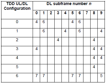
Let's read Table 8-2 the same way as the HARQ tables. Each row lists the downlink subframes n that can carry DCI 0 for this configuration, and the value k gives the PUSCH subframe n + k. The values are unchanged in 36.213 v19.4.0.
It says, for UL/DL configuration 1
- DCI 0 in subframe 1 schedules PUSCH in subframe 7, with k = 6
- DCI 0 in subframe 4 schedules PUSCH in subframe 8, with k = 4
- DCI 0 in subframe 6 schedules PUSCH in subframe 2 of the next SFN, with k = 6
- DCI 0 in subframe 9 schedules PUSCH in subframe 3 of the next SFN, with k = 4
Configuration 0 needs one more field. It has six uplink subframes but only four subframes that can carry DCI 0. So DCI format 0 carries a 2 bit UL index in configuration 0. With the MSB set, the PUSCH is in subframe n + k from the table. With the LSB set, the PUSCH is in subframe n + 7. With both bits set, the UE sends PUSCH in both subframes. That is how one DCI 0 schedules two uplink subframes, as the overview table says.
Table 8-2 gives the uplink grant delay : a DCI 0 in subframe n schedules PUSCH in subframe n + k.k is 4, 5, 6 or 7 depending on the row : the delay is never shorter than in FDD.Configuration 0 uses the UL index : one DCI 0 can schedule subframe n + k, subframe n + 7, or both.
Issues with Debugging
The timing tables above are hard to read, but at least they are fixed. The harder problem appears when a test fails and you have to find which PDSCH a NACK belongs to. Let's look at that problem with configuration 2.
What was your first impression about all the Ack-Nack report mechanism described above ?
My first impression was "So complicated !" and "So.. So.. So.. confusing".
Unfortunately.. there is more serious problem than the 'confusing things'. It is about troubleshooting issues.
Let's assume that you are using DL/UL Configuration 2. and suppose UE sent a NACK at Subframe 2.
How did you know whether the NACK is for PDSCH at subframe 4 or 5 or 6 or 8 ? (As you know, in FDD.. the answer is so simple since the ACK/NACK from the UE is always for the PDSCH that it received 4 subframe before. If it is FDD, the answer is supposed to be 'it is for PDSCH received at subframe 8 in previous SFN), but in TDD case it is different as you may guess.
|
Then how do you correlate the NACK to the specific PDSCH which caused the NACK. It is completely dependent on how much detailed information that your UE log or Network log provide. If UE log or Network log provide ACK/NACK information and HARQ process number for every subframe.. you can try following procedure.
|
This search works only when the log shows the HARQ process number of every PDSCH and every ACK/NACK. With bundling there is a second difficulty. One NACK bit covers several PDSCH, so the log alone cannot tell which one failed. The next section explains that feedback mode.
In FDD the ACK/NACK always refers to subframe n - 4 : in TDD it can refer to several subframes in the set K.The HARQ process number connects a NACK to its PDSCH : search the PDSCH list around the ACK/NACK for the same process.Bundling hides which PDSCH failed : one NACK bit covers all PDSCH of the bundling window.
Ack/Nack Feedback Mode
As described above, in TDD LTE ibe subframe can transmit ACK/NACK for multiple subframe as shown below. In the following figure as an example, UE send ACK/NACK for 4 PDSCHs in subframe 2. What should eNB do if the subframe 2 send NACK ? Does it have to retransmit the whole 4 PDSCHs ? or transmit only PDSCH which is NACKed ?
The answer to the question gets different depending on tdd-AckNackFeedbackMode setting in RRC message (e.g, RRC Connection Setup or RRC Connection Reconfiguration).
If it is set to be 'bundling', eNB should retransmit all the PDSCH. If it is sent to be 'multiplexing', eNB should retransmit the only PDSCH which is NACKed.
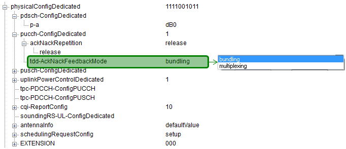
|
Followings are some of the items that is worth noticing from 3GPP 36.213 10.1.3 TDD HARQ-ACK feedback procedures (I revised the statement a little bit to make it simple and hopefully clearer)
|
You would notice the variable 'M' in many of the statement above. M is defined to be "the number of elements in the set K defined in Table 10.1.3.1-1". Following examples would give you clearer idea on the meaning of M.
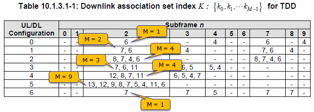
Bundling has one more risk, and TDD solves it with the Downlink Assignment Index. Suppose the UE misses the PDCCH of one PDSCH in the window and ACKs all the others. A bundled ACK would then look correct to the eNB, although one PDSCH was never received. The DAI field in the downlink DCI counts the assignments in the window, so the UE can detect a missing one and avoid sending a false ACK. 36.212 includes the 2 bit DAI for TDD operation with UL/DL configurations 1 to 6.
Bundling sends one ACK/NACK per codeword for the whole window : a single NACK makes the eNB retransmit every PDSCH of the window.Multiplexing keeps one ACK/NACK per subframe : the eNB retransmits only the PDSCH that failed.Configuration 5 supports only bundling : this applies to a UE without carrier aggregation, see 36.213 clause 10.1.3.DAI protects bundling against a missed PDCCH : the UE counts the assignments and does not send a false ACK when one is missing.
System Information Variation
A TDD UE cannot read anything useful until it knows the frame layout of the cell. The UL/DL configuration and the special subframe configuration are therefore broadcast in SIB1, in the tdd-Config field. An FDD cell leaves this field out.
The screenshot below is a decoded SIB1 from a band 41 cell. The two highlighted fields of tdd-Config point into the two tables of 36.211 on the right.
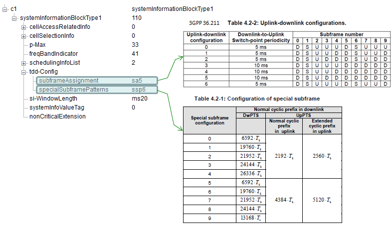
- freqBandIndicator 41 : a TDD band.
- subframeAssignment sa5 : UL/DL configuration 5 of Table 4.2-2, D S U D D D D D D D, with 10 ms switch-point periodicity.
- specialSubframePatterns ssp6 : special subframe configuration 6 of Table 4.2-1. With normal CP, that is a DwPTS of 19760 Ts, 9 symbols, a GP of 3 symbols and an UpPTS of 2 symbols.
The two fields are defined by the TDD-Config IE. Later releases added the extension IEs for configurations 7 and 9, 10, and 10 without CRS in DwPTS. SIB1 carries them in its v1130, v1430 and v1450 extensions.
Following is based on
TDD-Config ::=						SEQUENCE {
	subframeAssignment					ENUMERATED {
											sa0, sa1, sa2, sa3, sa4, sa5, sa6},
	specialSubframePatterns				ENUMERATED {
											ssp0, ssp1, ssp2, ssp3, ssp4,ssp5, ssp6, ssp7,
											ssp8}
}

TDD-Config-v1130 ::=				SEQUENCE {
	specialSubframePatterns-v1130		ENUMERATED {ssp7,ssp9}
}

TDD-Config-v1430 ::=				SEQUENCE {
	specialSubframePatterns-v1430		ENUMERATED {ssp10}
}

TDD-Config-v1450 ::=				SEQUENCE {
	specialSubframePatterns-v1450		ENUMERATED {ssp10-CRS-LessDwPTS}
}
The field descriptions add two rules. When one of the extension fields is present, the UE ignores specialSubframePatterns without suffix. And the eNB signals an extension value only together with a matching Release 8 value, for example ssp9 only when specialSubframePatterns is ssp5. So a UE of an earlier release still reads a valid configuration from the Release 8 field.
SIB1 tells the UE the frame layout : tdd-Config carries subframeAssignment and specialSubframePatterns.sa and ssp point into 36.211 tables : sa0 to sa6 into Table 4.2-2 and ssp0 to ssp8 into Table 4.2-1.Extensions carry the newer special subframe configurations : tdd-Config-v1130, v1430 and v1450 override the Release 8 value.
Reference
- 3GPP TS 36.211 v19.3.0 : Physical channels and modulation. Table 4.2-1 and Table 4.2-2, clause 5.7 Physical random access channel, clause 6.11.1 Primary synchronization signal.
- 3GPP TS 36.213 v19.4.0 : Physical layer procedures. Clause 7.1.7 TBS in DwPTS, Table 8-2, Table 9.1.2-1, clause 10.1.3 TDD HARQ-ACK feedback procedures, Table 10.1.3.1-1 and clause 10.1.5 Scheduling Request.
- 3GPP TS 36.212 v19.3.0 : Multiplexing and channel coding. Clause 5.3.3.1 DCI formats, the UL index and Downlink Assignment Index fields.
- 3GPP TS 36.331 v19.3.0 : Radio Resource Control. SystemInformationBlockType1 and TDD-Config.