From Rel 12, 3GPP defines (support) 256 QAM in Downlink. Conceptually, there would no problem with understanding the concept itself if you have basic knowledge of modulation and I/Q Constellation.
I see a lot of Physicall layer developer showing angry face at me when I say like this :). I know the implementation would be extremly difficult to implement this kind of higher modulation in wireless communication environment. Even though we need to implement this kind of higher modulation, we would not be allowed to increase downlink power for better resolution in constellation and for good enough SNR etc. So it will be very challenging not only for transmitter side (eNB) but also for reciever side (UE) as well.
- Would this be really feasible ? Why we care about it ?
- UE Capability Information
- MCS Table
- CQI Table
- RRC Message Examples
- How practical it would be ?
- Reference :
Would this be really feasible ? Why we care about it ?
Would it be really possible to provide a connection with 256 QAM in real network situation ? I think even 64 QAM can be challenging in some situation like in cell boundary or high interference environment. What is the point of developing 256 QAM then ?
It is true that 256 QAM would not work well in usual macro cell environment as we normally are in as of now (May 2015), but think of a situation where we are using a small cell and the UE is very close to the cell (as we are using WiFi HotSpot in a coffee shop). It would be feasible in this kind of situation and 3GPP intoduced 256 QAM as a part of Small Cell Enhancement feature.
The specification answers the question by making every part of it optional. A UE tells the network whether it can receive 256QAM, the network decides whether to switch the reporting table, and it decides separately whether to switch the transport block size table. All three stay off until the network turns them on.
The size of the gain is readable from the tables further down. The standard CQI table stops at an efficiency of 5.5547 bits per symbol and the alternative one reaches 7.4063, so the ceiling rises by about a third. That gain is available only at the very top of the range, where the channel is already good.
Every piece of it is optional : the capability, the CQI table and the transport block size table are switched on one at a time.The ceiling rises by about a third : 36.213 takes the top efficiency from 5.5547 to 7.4063 bits per symbol.The gain sits at the top of the range only : nothing below the highest few CQI indices changes for the better.A good channel is the precondition : 256QAM packs eight bits into a symbol, so the constellation points sit closer together.
UE Capability Information
To support 256 QAM, a couple of new IEs are added to UE Capability Information message as shown below. (This is understandable. Almost every new feature is added in 3GPP, those features has been added to UE capability informatoin. If you see UE capability information supporting all the latest feature as of now (May 2015), you would already see super long UE Capability Information message.. I am not sure how long the message will get as the technology evolves even further)

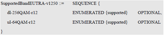
Following is an example UE Capability Information that indicate the support of DL 256 QAM.
+-nonCriticalExtension
+-phyLayerParameters-v1170 = Omit
+-ue-Category-v1170 = 9
+-nonCriticalExtension = 00001
+-rf-Parameters-v1180 = Omit
+-mbms-Parameters-r11 = Omit
+-fdd-Add-UE-EUTRA-Capabilities-v1180 = Omit
+-tdd-Add-UE-EUTRA-Capabilities-v1180 = Omit
+-nonCriticalExtension
+-ue-Category-v11a0 = 11
+-measParameters-v11a0 = Omit
+-nonCriticalExtension
+-phyLayerParameters-v1250 = Omit
+-rf-Parameters-v1250
| +-supportedBandListEUTRA-v1250 = 5
| | +-SupportedBandEUTRA-v1250
| | | +-dl-256QAM-r12 = supported
| | | +-ul-64QAM-r12 = supported
| | +-SupportedBandEUTRA-v1250
| | | +-dl-256QAM-r12 = supported
| | | +-ul-64QAM-r12 = supported
| | +-SupportedBandEUTRA-v1250
| | | +-dl-256QAM-r12 = supported
| | | +-ul-64QAM-r12 = supported
| | +-SupportedBandEUTRA-v1250
| | | +-dl-256QAM-r12 = supported
| | | +-ul-64QAM-r12 = supported
| | +-SupportedBandEUTRA-v1250
| | +-dl-256QAM-r12 = supported
| | +-ul-64QAM-r12 = supported
The structure in the two listings above settles one thing worth knowing. SupportedBandListEUTRA-v1250 is a sequence over bands, so the capability is reported per band rather than once for the UE. A handset can support 256QAM on one band and not on another, and the network has to read the entry for the band it wants to use.
The same structure carries the uplink counterpart. 36.331 v19.3.0 gives SupportedBandEUTRA-v1250 two fields, dl-256QAM-r12 and ul-64QAM-r12, and both are ENUMERATED with the single value supported and both are optional. An absent field is the way a UE says no, because there is no value that means unsupported.
The capability is per band : SupportedBandListEUTRA-v1250 is a sequence over bands, one entry each.Downlink and uplink sit together : dl-256QAM-r12 sits beside ul-64QAM-r12 in the same structure.Absence is the negative : the enumeration has one value, supported, so omission is how a UE declines.Both fields are still current : 36.331 v19.3.0 defines SupportedBandEUTRA-v1250 exactly as the listing shows.
MCS Table
When I first heard of 256 QAM, the first thing popped up in my mind was 'we may need additional MCS index to indicate 256 QAM' and then 'how to handle the backward compatibility issue' etc.
But it turned out that the number of MCS index itself has no change (no additional MCS index). However, 3GPP defined a new MCS table as shown in 36.213 Table 7.1.7.1-1A.
|
< 36.213 Table 7.1.7.1-1 > |
< 36.213 - Rel 12 Table 7.1.7.1-1A > |
|
|
|
|
|
|
|
< 36.213 - Rel 13, Table 7.1.7.1-1 > |
< 36.213 - Rel 13, Table 7.1.7.1-1A. > |
|
|
|


Then you may ask how UE can figure out which of these two tables (conventional table and the new table) it has to use ?
It should be informed to UE by higher layer. The short answer is that the same IE specifying CQI table is used to indicate which MCS table to use. This is based on 36.213 7.1.7.1 Modulation order determination as stated below : (This rule changes as LTE evolves.. I would put down multiple different versions of description so that you can get some idea on how this evolves.
< Release 12 > --------------------------------------------------
if the higher layer parameter altCQI-Table-r12 is configured, and if the PDSCH is assigned by a PDCCH/EPDCCH with DCI format 1/1B/1D/2/2A/2B/2C/2D with CRC scrambled by C-RNTI,
- the UE shall use I_MCS and Table 7.1.7.1-1A to determine the modulation order ( Qm ) used in the physical downlink shared channel.
- else
- the UE shall use I_MCS and Table 7.1.7.1-1 to determine the modulation order ( Qm ) used in the physical downlink shared channel.
< Release 13 > --------------------------------------------------
- if the higher layer parameter altCQI-Table-r12 is configured, and if the PDSCH is assigned by a PDCCH/EPDCCH with DCI format 1/1B/1D/2/2A/2B/2C/2D with CRC scrambled by C-RNTI,
- if the assigned PDSCH is transmitted only in the second slot of a subframe, the UE shall use MCS_I and Table
7.1.7.1-1A to determine the modulation order (Q'm). The modulation order (Qm) used in the physical downlink shared channel is set to Qm = Q'm ;
- otherwise, the UE shall use MCS I and Table 7.1.7.1-1A to determine the modulation order (Qm) used in the
physical downlink shared channel.
- else
- if the assigned PDSCH is transmitted only in the second slot of a subframe, the UE shall use MCS_I and Table
7.1.7.1-1 to determine the modulation order (Qm). The modulation order (Qm) used in the physical downlink
shared channel is set to Qm = Q'm ;
- otherwise, the UE shall use MCS_I and Table 7.1.7.1-1 to determine the modulation order (Qm) used in the
physical downlink shared channel.
In Release 13, you would notice there is a new TBS index called 26A and 33A is added. This new index value is described in 36.213 7.1.7.2 Transport block size determination as follows :
When RNTI type is C_RNTI and the higher layer parameter altCQI-Table-r12 IS NOT configured :
- For 0 <= I_MCS <= 28 ,
- the UE shall first determine the TBS index ( I_TBS ) using I_MCS and Table 7.1.7.1-1 except the case where the transport block is disabled in DCI formats 2, 2A, 2B, 2C and 2D.
- For I_MCS = 28,
- if the UE is scheduled by DCI formats 2C/2D and is configured with a26 in tbsIndexAlt, I_TBS is 26A;
- otherwise TBS I is 26.
When RNTI type is C_RNTI and the higher layer parameter altCQI-Table-r12 IS configured and DCI format is DCI format 1/1B/1D/2/2A/2B/2C/2D :
- For 0 ≤ I_MCS ≤ 27, the UE shall first determine the TBS index (I_TBS) using I_MCS and Table 7.1.7.1-1A except the case where the transport block is disabled in DCI formats 2, 2A, 2B, 2C and 2D.
- For I_MCS = 27,
- if the UE is scheduled by DCI formats 2C/2D and is configured with a33 in tbsIndexAlt, TBS I is 33A;
- otherwise TBS I is 33.
Following is based on
PhysicalConfigDedicatedSCell-r10 ::=    SEQUENCE {
    ....
    [[  pdsch-ConfigDedicated-v1280     PDSCH-ConfigDedicated-v1280
                                                    OPTIONAL    -- Need ON
    ]],
    ....
}

PDSCH-ConfigDedicated-v1280 ::=         SEQUENCE {
    tbsIndexAlt-r12                     ENUMERATED {a26, a33}
                                                    OPTIONAL    -- Need OR
}
The elision above is the page's own, and the two lines around it are what 36.331 v19.3.0 adds. The field sits inside a release extension group rather than in the body of the structure. It is marked Need ON, so a reconfiguration that omits it leaves the earlier value in place.
< 36.213 Table 7.1.7.2.1-1: Transport block size table >


You can see some real examples of RRC message to enable 256 QAM for PCC and SCC in RRC Message Example section.
CQI Table
As in MCS table, CQI table is also redefined for 256 QAM. As shown in the table below, you would notice that the total number of CQI value stay same but the modulation mapping to each CQI index is redefined in 256 QAM (Table 7.2.3-2)
|
< 36.213 Table 7.2.3-1 > |
< 36.213 Table 7.2.3-2 > |
|
|
|


Then how can UE figure out which table it has to apply when it is reporting CQI ? It is instructed by Network via an RRC message as shown below.

Reading the two tables side by side shows what the alternative one really does. It does not add four rows to the end. Both tables have sixteen entries, and the alternative spends them differently.
The extra room comes from the bottom of the range. The standard table gives QPSK six entries and 16QAM three. The alternative gives QPSK three and 16QAM three, drops 64QAM from six entries to five, and uses the four it has freed for 256QAM. A UE on the alternative table therefore reports a weak channel with less resolution than before.
One field decides which table is in force. 36.331 gives altCQI-Table-r12 the values allSubframes, csi-SubframeSet1 and csi-SubframeSet2. The field description says it indicates the applicability of the alternative CQI table for both aperiodic and periodic CSI reporting on the serving cell concerned. Value allSubframes applies it to every subframe and every CSI process.
Release 15 added a second field beside it. 36.331 v19.3.0 carries altCQI-Table-1024QAM-r15 with the same three values, pointing at a further pair of tables, so the mechanism this page describes was reused rather than replaced.
Both tables hold sixteen entries : the alternative one re-spends the codepoints rather than extending the list.QPSK loses half its rows : six entries in 36.213 Table 7.2.3-1 against three in Table 7.2.3-2.256QAM takes four of them : CQI 12 to 15, with code rates 711, 797, 885 and 948 out of 1024.altCQI-Table-r12 makes the choice : allSubframes applies the alternative table to every subframe and CSI process.Release 15 did the same again : altCQI-Table-1024QAM-r15 does the same job for a further pair of tables.
RRC Message Examples
Two captures follow, and they are worth comparing rather than reading one at a time. The first switches 256QAM on for the primary carrier and the second does it for a secondary one. The setting sits in a different place in each.
Example 1, Enabling 256 QAM for PCC
This one configures the primary cell, so the setting travels inside the dedicated physical configuration of the cell the UE is already on. Look for pdsch-ConfigDedicated and the tbsIndexAlt value underneath it.
RRC Connection Reconfiguration enabling 256QAM on the primary carrier, decoded as a tree,
+-rrcConnectionReconfiguration ::= SEQUENCE
  +-rrc-TransactionIdentifier ::= INTEGER (0..3) [0]
  +-criticalExtensions ::= CHOICE [c1]
    +-c1 ::= CHOICE [rrcConnectionReconfiguration-r8]
      +-rrcConnectionReconfiguration-r8 ::= SEQUENCE [001100]
        +-measConfig ::= SEQUENCE OPTIONAL:Omit
        +-mobilityControlInfo ::= SEQUENCE OPTIONAL:Omit
        +-dedicatedInfoNASList ::= SEQUENCE OF SIZE(1..maxDRB[11]) [1] OPTIONAL:Exist
        | +-DedicatedInfoNAS ::= OCTET STRING SIZE(ALIGNED)
        +-radioResourceConfigDedicated ::= SEQUENCE [110101] OPTIONAL:Exist
        | +-srb-ToAddModList ::= SEQUENCE OF SIZE(1..2) [1] OPTIONAL:Exist
        | | +-SRB-ToAddMod ::= SEQUENCE [11]
        | +-drb-ToAddModList ::= SEQUENCE OF SIZE(1..maxDRB[11]) [1] OPTIONAL:Exist
        | | +-DRB-ToAddMod ::= SEQUENCE [11111]
        | +-drb-ToReleaseList ::= SEQUENCE OF OPTIONAL:Omit
        | +-mac-MainConfig ::= CHOICE [explicitValue] OPTIONAL:Exist
        | +-sps-Config ::= SEQUENCE OPTIONAL:Omit
        | +-physicalConfigDedicated ::= SEQUENCE [0100110010] OPTIONAL:Exist
        | | +-pdsch-ConfigDedicated ::= SEQUENCE OPTIONAL:Omit
        | | +-pucch-ConfigDedicated ::= SEQUENCE [0] OPTIONAL:Exist
        | | +-uplinkPowerControlDedicated ::= SEQUENCE OPTIONAL:Omit
        | | +-tpc-PDCCH-ConfigPUSCH ::= CHOICE [setup] OPTIONAL:Exist
        | | +-cqi-ReportConfig ::= SEQUENCE OPTIONAL:Omit
        | | +-soundingRS-UL-ConfigDedicated ::= CHOICE OPTIONAL:Omit
        | | +-antennaInfo ::= CHOICE [explicitValue] OPTIONAL:Exist
        | | +-schedulingRequestConfig ::= CHOICE OPTIONAL:Omit
        | | +-EXTENSION ::= SEQUENCE [00001]
        | |   +-VERSION-BRACKETS1 ::= SEQUENCE OPTIONAL:Omit
        | |   +-VERSION-BRACKETS2 ::= SEQUENCE OPTIONAL:Omit
        | |   +-VERSION-BRACKETS3 ::= SEQUENCE OPTIONAL:Omit
        | |   +-VERSION-BRACKETS4 ::= SEQUENCE OPTIONAL:Omit
        | |   +-VERSION-BRACKETS5 ::= SEQUENCE [00001000] OPTIONAL:Exist
        | |     +-antennaInfo-v1250 ::= SEQUENCE OPTIONAL:Omit
        | |     +-eimta-MainConfig-r12 ::= CHOICE OPTIONAL:Omit
        | |     +-eimta-MainConfigPCell-r12 ::= CHOICE OPTIONAL:Omit
        | |     +-pucch-ConfigDedicated-v1250 ::= SEQUENCE OPTIONAL:Omit
        | |     +-cqi-ReportConfigPCell-v1250 ::= SEQUENCE [0001] OPTIONAL:Exist
        | |     | +-csi-SubframePatternConfig-r12 ::= CHOICE OPTIONAL:Omit
        | |     | +-cqi-ReportBoth-v1250 ::= SEQUENCE OPTIONAL:Omit
        | |     | +-cqi-ReportAperiodic-v1250 ::= CHOICE OPTIONAL:Omit
        | |     | +-altCQI-Table-r12 ::= ENUMERATED [allSubframes] OPTIONAL:Exist
        | |     +-uplinkPowerControlDedicated-v1250 ::= SEQUENCE OPTIONAL:Omit
        | |     +-pusch-ConfigDedicated-v1250 ::= SEQUENCE OPTIONAL:Omit
        | |     +-csi-RS-Config-v1250 ::= SEQUENCE OPTIONAL:Omit
        | +-EXTENSION ::= SEQUENCE [0000]
        |   +-VERSION-BRACKETS1 ::= SEQUENCE OPTIONAL:Omit
        |   +-VERSION-BRACKETS2 ::= SEQUENCE OPTIONAL:Omit
        |   +-VERSION-BRACKETS3 ::= SEQUENCE OPTIONAL:Omit
        |   +-VERSION-BRACKETS4 ::= SEQUENCE OPTIONAL:Omit
HEX : 20 06 03 59 39 1E 4E 24 30 18 3A 10 17 00 30 00 07 88 80 00 08 01 B2 90 FE 08 08 48 68 23 4B 73 2B A0 23 13 2B 63 60 13 1B 08 28 0E 05 40 08 09 38 DC 04 01 08 80 18 00 00 84 08 36 05 40 08 14 18 36 05 40 08 10 00 68 26 05 40 08 12 80 5F B0 07 88 84 00 08 00 00 00 00 08 98 07 88 80 00 09 18 2F A0 00 00 00 08 BF 02 CF 03 20 08 1F 93 53 E0 FA 81 BC 0F A8 E0 60 78 E6 3E 9D 52 D2 E8 00 FB 5E 64 88 1F F8 20 3F 40 50 C1 C2 00 82 04 00
Example 2, Enabling 256 QAM for SCC
The secondary cell case puts the same setting one level deeper, inside the cell being added. The decode is longer for that reason rather than because anything about 256QAM has changed between the two.
RRC Connection Reconfiguration enabling 256QAM on a secondary carrier, decoded as a tree,
+-rrcConnectionReconfiguration-r8 ::= SEQUENCE [000101]
  +-measConfig ::= SEQUENCE OPTIONAL:Omit
  +-mobilityControlInfo ::= SEQUENCE OPTIONAL:Omit
  +-dedicatedInfoNASList ::= SEQUENCE OF OPTIONAL:Omit
  +-radioResourceConfigDedicated ::= SEQUENCE [000001] OPTIONAL:Exist
  | +-srb-ToAddModList ::= SEQUENCE OF OPTIONAL:Omit
  | +-drb-ToAddModList ::= SEQUENCE OF OPTIONAL:Omit
  | +-drb-ToReleaseList ::= SEQUENCE OF OPTIONAL:Omit
  | +-mac-MainConfig ::= CHOICE OPTIONAL:Omit
  | +-sps-Config ::= SEQUENCE OPTIONAL:Omit
  | +-physicalConfigDedicated ::= SEQUENCE [0000000000] OPTIONAL:Exist
  | | +-pdsch-ConfigDedicated ::= SEQUENCE OPTIONAL:Omit
  | | +-pucch-ConfigDedicated ::= SEQUENCE OPTIONAL:Omit
  | | +-pusch-ConfigDedicated ::= SEQUENCE OPTIONAL:Omit
  | | +-uplinkPowerControlDedicated ::= SEQUENCE OPTIONAL:Omit
  | | +-tpc-PDCCH-ConfigPUCCH ::= CHOICE OPTIONAL:Omit
  | | +-tpc-PDCCH-ConfigPUSCH ::= CHOICE OPTIONAL:Omit
  | | +-cqi-ReportConfig ::= SEQUENCE OPTIONAL:Omit
  | | +-soundingRS-UL-ConfigDedicated ::= CHOICE OPTIONAL:Omit
  | | +-antennaInfo ::= CHOICE OPTIONAL:Omit
  | | +-schedulingRequestConfig ::= CHOICE OPTIONAL:Omit
  | | +-EXTENSION ::= SEQUENCE [01000000]
  | |   +-VERSION-BRACKETS1 ::= SEQUENCE OPTIONAL:Omit
  | |   +-VERSION-BRACKETS2 ::= SEQUENCE [00000100000] OPTIONAL:Exist
  | |   | +-antennaInfo-r10 ::= CHOICE OPTIONAL:Omit
  | |   | +-antennaInfoUL-r10 ::= SEQUENCE OPTIONAL:Omit
  | |   | +-cif-Presence-r10 ::= BOOLEAN OPTIONAL:Omit
  | |   | +-cqi-ReportConfig-r10 ::= SEQUENCE OPTIONAL:Omit
  | |   | +-csi-RS-Config-r10 ::= SEQUENCE OPTIONAL:Omit
  | |   | +-pucch-ConfigDedicated-v1020 ::= SEQUENCE [1000] OPTIONAL:Exist
  | |   | | +-pucch-Format-r10 ::= CHOICE [channelSelection-r10] OPTIONAL:Exist
  | |   | | | +-channelSelection-r10 ::= SEQUENCE [1]
  | |   | | |   +-n1PUCCH-AN-CS-r10 ::= CHOICE [setup] OPTIONAL:Exist
  | |   | | |     +-setup ::= SEQUENCE
  | |   | | |       +-n1PUCCH-AN-CS-List-r10 ::= SEQUENCE OF SIZE(1..2) [2]
  | |   | | |         +-N1PUCCH-AN-CS-r10 ::= SEQUENCE OF SIZE(1..4) [4]
  | |   | | |         | +- ::= INTEGER (0..2047) [101]
  | |   | | |         | +- ::= INTEGER (0..2047) [102]
  | |   | | |         | +- ::= INTEGER (0..2047) [103]
  | |   | | |         | +- ::= INTEGER (0..2047) [104]
  | |   | | |         +-N1PUCCH-AN-CS-r10 ::= SEQUENCE OF SIZE(1..4) [4]
  | |   | | |           +- ::= INTEGER (0..2047) [105]
  | |   | | |           +- ::= INTEGER (0..2047) [106]
  | |   | | |           +- ::= INTEGER (0..2047) [107]
  | |   | | |           +- ::= INTEGER (0..2047) [108]
  | |   | | +-twoAntennaPortActivatedPUCCH-Format1a1b-r10 ::= ENUMERATED OPTIONAL:Omit
  | |   | | +-simultaneousPUCCH-PUSCH-r10 ::= ENUMERATED OPTIONAL:Omit
  | |   | | +-n1PUCCH-AN-RepP1-r10 ::= INTEGER OPTIONAL:Omit
  | |   | +-pusch-ConfigDedicated-v1020 ::= SEQUENCE OPTIONAL:Omit
  | |   | +-schedulingRequestConfig-v1020 ::= SEQUENCE OPTIONAL:Omit
  | |   | +-soundingRS-UL-ConfigDedicated-v1020 ::= SEQUENCE OPTIONAL:Omit
  | |   | +-soundingRS-UL-ConfigDedicatedAperiodic-r10 ::= CHOICE OPTIONAL:Omit
  | |   | +-uplinkPowerControlDedicated-v1020 ::= SEQUENCE OPTIONAL:Omit
  | +-EXTENSION ::= SEQUENCE [00000]
  +-securityConfigHO ::= SEQUENCE OPTIONAL:Omit
  +-nonCriticalExtension ::= SEQUENCE [01] OPTIONAL:Exist
    +-lateNonCriticalExtension ::= OCTET STRING OPTIONAL:Omit
    +-nonCriticalExtension ::= SEQUENCE [001] OPTIONAL:Exist
      +-otherConfig-r9 ::= SEQUENCE OPTIONAL:Omit
      +-fullConfig-r9 ::= ENUMERATED OPTIONAL:Omit
      +-nonCriticalExtension ::= SEQUENCE [010] OPTIONAL:Exist
        +-sCellToReleaseList-r10 ::= SEQUENCE OF OPTIONAL:Omit
        +-sCellToAddModList-r10 ::= SEQUENCE OF SIZE(1..maxSCell-r10[4]) [1] OPTIONAL:Exist
        | +-SCellToAddMod-r10 ::= SEQUENCE [111]
        |   +-sCellIndex-r10 ::= INTEGER (1..7) [1]
        |   +-cellIdentification-r10 ::= SEQUENCE OPTIONAL:Exist
        |   | +-physCellId-r10 ::= INTEGER (0..503) [1]
        |   | +-dl-CarrierFreq-r10 ::= INTEGER (0..maxEARFCN[65535]) [3048]
        |   +-radioResourceConfigCommonSCell-r10 ::= SEQUENCE [0] OPTIONAL:Exist
        |   | +-nonUL-Configuration-r10 ::= SEQUENCE [00]
        |   | +-ul-Configuration-r10 ::= SEQUENCE OPTIONAL:Omit
        |   | +-EXTENSION ::= SEQUENCE [0000]
        |   +-radioResourceConfigDedicatedSCell-r10 ::= SEQUENCE [1] OPTIONAL:Exist
        |   | +-physicalConfigDedicatedSCell-r10 ::= SEQUENCE [10] OPTIONAL:Exist
        |   | | +-nonUL-Configuration-r10 ::= SEQUENCE [1001] OPTIONAL:Exist
        |   | | +-ul-Configuration-r10 ::= SEQUENCE OPTIONAL:Omit
        |   | | +-EXTENSION ::= SEQUENCE [01000]
        |   | |   +-VERSION-BRACKETS1 ::= SEQUENCE OPTIONAL:Omit
        |   | |   +-VERSION-BRACKETS2 ::= SEQUENCE [00100] OPTIONAL:Exist
        |   | |   | +-antennaInfo-v1250 ::= SEQUENCE OPTIONAL:Omit
        |   | |   | +-eimta-MainConfigSCell-r12 ::= CHOICE OPTIONAL:Omit
        |   | |   | +-cqi-ReportConfigSCell-v1250 ::= SEQUENCE [0001] OPTIONAL:Exist
        |   | |   | | +-csi-SubframePatternConfig-r12 ::= CHOICE OPTIONAL:Omit
        |   | |   | | +-cqi-ReportBoth-v1250 ::= SEQUENCE OPTIONAL:Omit
        |   | |   | | +-cqi-ReportAperiodic-v1250 ::= CHOICE OPTIONAL:Omit
        |   | |   | | +-altCQI-Table-r12 ::= ENUMERATED [allSubframes] OPTIONAL:Exist
        |   | |   | +-uplinkPowerControlDedicatedSCell-v1250 ::= SEQUENCE OPTIONAL:Omit
        |   | |   | +-csi-RS-Config-v1250 ::= SEQUENCE OPTIONAL:Omit
        |   | |   +-VERSION-BRACKETS3 ::= SEQUENCE OPTIONAL:Omit
        |   | |   +-VERSION-BRACKETS4 ::= SEQUENCE OPTIONAL:Omit
        |   | |   +-VERSION-BRACKETS5 ::= SEQUENCE OPTIONAL:Omit
        |   | +-EXTENSION ::= SEQUENCE [000]
        |   +-EXTENSION ::= SEQUENCE [00]
        +-nonCriticalExtension ::= SEQUENCE OPTIONAL:Omit
HEX : 20 02 81 80 01 D0 03 81 04 7E 19 43 30 67 0D 18 69 0D 41 AC 36 12 87 00 10 BE 80 A8 9C 3A 64 05 90 44 01 10 40 00
How practical it would be ?
When I first heard of 256 QAM will be supported in LTE, the first question poping up in my mind was "Is it reailly feasible ? Would it be practically usable in real network in the field ?".
To get some rought answer to this question, let's think of SNR vs BER characteristics. This can be illustrated as below. This illustrates the correllation between SNR and BER based on the assumption that no channel coding or any kind of error correction were used (If you are not familiar with how to interprete this graph, refer to SNR page for the detailed explanation).
According to this graph, If we want to use 256QAM without any channel coding/error correction, it would be safe to use 256 QAM at SNR higher than 35 dB (marked as section (A)) and may be usable as well at 30~35 dB (marked as section (B)).

Then the question would be "would it be practically easy to have live network channel condition with SNR of 35 dB or greater ?". It would be very unlikely unless you have all of the following conditions met.
i) Radio Channel Condition is extremely good
ii) The performance of ADC/DAC converter is extremly good
iii) Transmitter and Reciever RF path design / implementation should be extremly good
iv) Very efficient Error Correction method should be used
In real life, we have no control over item i). We should rely completely on mother nature for this. However if it is in testing condition in the lab, we would have great degree of control for this.
Item ii) is completely up to radio modem designer/vendor because this would be fixed at the design phase and once this is determined, it would be almost impossible to change the performance afterwords. Especially determining ADC/DAC bit resolution would be crucial. As you see in ADC page, with 1 bit larger or smaller bit resultion you would gain or lose around 6 dB SNR.
Of course, Item iii) will be handled by RF designer. The noise figure of all the components and traces between those components should be very low. When you have plan to use 256QAM in multi channel configuration (e.g, Carrier Aggregation.. especially Carrier Aggregation in continguous channels), ACLR/ACPR characteristics should be extrememly good.
Item iv). I don't think anybody can have control over this once 3GPP Technical Specification is released.
Assuming that all of these conditions are met and thanks to Error Correction algorithm being used in LTE, we would have a better performanace (measured as throughput or BLER) comparing to what we estimated based on BER. A result from R4-151580 (Ref [1]) shows more realistic performance as shown below. According to this plot, you may say you would get almost 100% peak throughput (i.e, 0% BLER) around 30 dB SNR. However, one thing to be noticed is that the throughput would drop by 50% with only 2 dB SNR change at slighly lower than 30 dB SNR. This is 2 x 2 and 2 layer case. If it is 4 x 4 and 4 layers, the performance would degrade further. Number of Tx antenna itself would not be the culprit of the performance degradation. The degradation would come from practical reasons. It would be very diffcult to design / implement in such a way that the noise figure the Tx / Rx path remain very low for all RF path when the number of Antenna gets larger.

< R4-151580 : Figure 3. Simulation results for 256QAM SDR test >
Reference :
[1] R4-151580 : 3GPP TSG-RAN WG4 #74bis Rio de Janeiro, Brazil, 20th – 24th April 2015
[2] 36.331 : 3GPP - E-UTRA; Radio Resource Control, v19.3.0. SupportedBandEUTRA-v1250 carries dl-256QAM-r12, PDSCH-ConfigDedicated-v1280 carries tbsIndexAlt-r12, and altCQI-Table-r12 selects the alternative CQI table.
[3] 36.213 : 3GPP - E-UTRA; Physical layer procedures. Table 7.1.7.1-1 and Table 7.1.7.1-1A are the MCS tables above, and Table 7.2.3-1 and Table 7.2.3-2 are the two CQI tables.