LTE BL/CE can operate in two different mode and these two mode are specified for RRC Connected state. The operation mode are configured by the eNB. In general, which mode to use is dependent on CE Level. (Ref [4])
- CE Mode A
- CE Mode B
- Mode vs Level vs Preamble Group
- How to Configure CE Mode ?
- PDSCH / PUSCH / PUCCH Max Repetition Differences between CE Mode A and B
- RACH Random Access Response Grant Content field size difference between CE Mode A and B
- CE Mode A and CE Mode B side by side
- What changed after Release 13
- Reference
CE Mode A
The name says coverage enhancement, but the useful way to read CE mode A is as the mode that keeps legacy LTE working. Almost every mechanism is the one an ordinary UE uses. Repetition is added only where the reduced bandwidth and the single receiver leave a gap.
- No repetition or small number of repetition (Ref [4])
- Operation in CE Mode A would have an equivalent coverage as that of UE Category 1. The difference in coverage between LTE-M1 and UE Category 1 lies in the fact that LTE-M1 uses only 1 Rx, 6 PRB narrowband and reduced uplink transmit power. The redeuced Uplink power in LTE-M1 is compensated by utilising a small number of repetitions.(Ref [4])
- Power control mechanism is same as in legacy LTE(non-MTC) power control mechanism. Basically Uplink power is controlled by DCI format 6-0A(UL Grant=PUSCH Scheduling),6-1A(PDSCH Scheduling),3,3A. If the transmission is in repetition mode, the power remain same within the same repetition period (36.213-5.1.1.1,5.1.2.1)
Four concrete numbers follow from that. The downlink ceiling is r16 or r32 and the uplink ceiling is r8, r16 or r32. The PUCCH repeats r1 to r8 times, and the uplink grant inside a random access response is 20 bits wide.
The scheduling side is legacy too. DCI format 6-0A schedules the PUSCH and 6-1A the PDSCH, and both carry a TPC field. The repetition number field in each is two bits wide, so a grant selects one of four levels below the ceiling.
HARQ is where the mode sits furthest from CE mode B. A CE mode A UE runs up to eight HARQ processes in each direction, which is the legacy FDD figure. It can therefore keep several transport blocks in flight while the repetitions of each are still going out.
Power control still works : both DCI formats carry a TPC field, and 36.213 holds the power steady across a repetition period rather than within it.The repetition number field is two bits : four levels to choose from, against eight in CE mode B, because the range it covers is far smaller.Eight HARQ processes in each direction : the same number an ordinary FDD UE has, so pipelining is still possible.Coverage enhancement levels 0 and 1 map here : 36.213 reads the level the UE used for the PRACH and interprets those two as CE mode A.
CE Mode B
CE mode B is the other extreme, and it gives up control to buy range. A UE this deep in coverage cannot be reached by adjusting power or modulation. The mode drops both and spends subframes instead, which is the only resource still available to it.
- Large number of repetitions(Ref [4])
- CE Mode B has coverage up to 15 dB coverage enhancement with reference to that of UE Category 1.(Ref [4])
- Transmission power for both PUCCH and PUSCH is set to be MAX. Since the power does not changes (i.e, no power control is performed) DCI format 6-0B and 6-1B does not carry TPC(Trnasmission Power Control) field. As you may guess, this mode is designed to be used in very poor propagation condition.(36.213-5.1.1.1,5.1.2.1)
The numbers are an order of magnitude away from the CE mode A ones. The downlink and uplink ceilings both start at r192 and run to r2048. The PUCCH repeats r4 to r32 times, and the uplink grant in a random access response is only 12 bits wide.
That shorter grant shows the trade most clearly. Twelve bits cannot carry an MCS field, a TPC field, a CSI request or an uplink delay bit, so all four are set to zero width. What the grant does carry is a wider repetition number field, three bits rather than two. Eight levels are needed across a range that reaches two thousand repetitions.
HARQ shrinks to match. A CE mode B UE runs two HARQ processes in each direction, or four when multi transport block scheduling is configured. A single bundle already occupies the subframes a second process would need.
No power control at all : transmission is at maximum power, so DCI formats 6-0B and 6-1B carry no TPC field.The repetition number field is three bits : eight levels, because the ceiling reaches 2048 and the steps below it have to stay usable.Two HARQ processes, not eight : one bundle occupies the subframes the others would need.Coverage enhancement levels 2 and 3 map here : the same clause that sends levels 0 and 1 to CE mode A sends these two to CE mode B.
Mode vs Level vs Preamble Group
When you read the specifications of LTE M1(BL/CE) or any other technical documents, you often see the cases where CEmode is used with CE Level and sometimes with RACH Preamble Group, and got confused a lot. My suggestion is
- Understand the concept of CE Mode and CE Level first
- Understand how CE Mode and CE Levels are related (The table in CE Level page would give you the answer)
- Understand how UE notifies the network about the CE Mode / Level it is taking (See Preamble Group page)
The short answer to the confusion is that the three names belong to three different moments. The coverage enhancement level is chosen first, by the UE and from its own measurement. The preamble group is how that choice is announced, because the eNB has nothing else to read before the first message. The CE mode comes last, and it is the network telling a connected UE which set of procedures to use.
The level comes from RSRP. 36.321 has the UE compare its measurement against the thresholds in rsrp-ThresholdsPrachInfoList and settle on a level from 0 to 3. The deepest UE picks level 3 and a UE in good coverage picks level 0.
The preamble carries that level to the eNB. One block of preamble indices belongs to each level, and preambleMappingInfo-r13 is what divides the 64 of them up. The index alone therefore says how deep the UE thinks it is, before any message has been decoded.
The mode then follows from the level. 36.213 clause 6.2 reads levels 0 and 1 as CE mode A and levels 2 and 3 as CE mode B. That is how a UE still in random access knows which column of every table applies to it. Once the connection exists, ce-Mode-r13 overrides that inference with an explicit setting.
The level is measured, the mode is configured : the UE picks the level from RSRP, and the network picks the mode in an RRC message.The preamble group is the carrier, not a third concept : it exists so the level can reach the eNB before any message can.Four levels collapse onto two modes : 0 and 1 become CE mode A, 2 and 3 become CE mode B, and nothing else maps between them.The mapping is only a default : ce-Mode-r13 replaces it as soon as the network sends one.
How to Configure CE Mode ?
The mode is not broadcast and it is not derived from anything the UE measures once a connection exists. It arrives in a dedicated message, inside the physical layer configuration, which means a UE has no mode of its own until the network gives it one.
Network can configure CE Mode via the following IE in a RRC Message like RRC Connection Setup, RRCConnectionReconfiguration or RRCConnectionReestablishment
Following is based on
PhysicalConfigDedicated ::=         SEQUENCE {
    ...,
    [[  ...
        ce-Mode-r13                 CHOICE {
            release                     NULL,
            setup                       ENUMERATED {ce-ModeA,ce-ModeB}
        }                                                               OPTIONAL,   -- Need ON
        ...
    ]],
    ...
}
Two details of the listing are worth reading before the decode below. The field is a CHOICE with a release branch, so a network can take the mode away again as well as set it. It is also marked Need ON. A UE that receives a reconfiguration without it therefore keeps whatever mode it already had.
The enumeration has exactly two values and no default. A UE that has never been given ce-Mode-r13 is therefore in neither mode by configuration, and 36.213 falls back on the coverage enhancement level the UE used for the PRACH. Levels 0 and 1 are read as CE mode A and levels 2 and 3 as CE mode B.
Captured from a live network, not quoted from a specification. The field names follow
Example 1 > ====================================================================
+-rrcConnectionSetup-r8 ::= SEQUENCE [0]
  +-radioResourceConfigDedicated ::= SEQUENCE [100101]
  | +-srb-ToAddModList ::= SEQUENCE OF SIZE(1..2) [1] OPTIONAL:Exist
  | +-drb-ToAddModList ::= SEQUENCE OF OPTIONAL:Omit
  | +-drb-ToReleaseList ::= SEQUENCE OF OPTIONAL:Omit
  | +-mac-MainConfig ::= CHOICE [explicitValue] OPTIONAL:Exist
  | +-sps-Config ::= SEQUENCE OPTIONAL:Omit
  | +-physicalConfigDedicated ::= SEQUENCE [1101000011] OPTIONAL:Exist
  | | +-pdsch-ConfigDedicated ::= SEQUENCE OPTIONAL:Exist
  | | +-pucch-ConfigDedicated ::= SEQUENCE [0] OPTIONAL:Exist
  | | +-pusch-ConfigDedicated ::= SEQUENCE OPTIONAL:Omit
  | | +-uplinkPowerControlDedicated ::= SEQUENCE [1] OPTIONAL:Exist
  | | +-tpc-PDCCH-ConfigPUCCH ::= CHOICE OPTIONAL:Omit
  | | +-tpc-PDCCH-ConfigPUSCH ::= CHOICE OPTIONAL:Omit
  | | +-cqi-ReportConfig ::= SEQUENCE OPTIONAL:Omit
  | | +-soundingRS-UL-ConfigDedicated ::= CHOICE OPTIONAL:Omit
  | | +-antennaInfo ::= CHOICE [defaultValue] OPTIONAL:Exist
  | | +-schedulingRequestConfig ::= CHOICE [setup] OPTIONAL:Exist
  | | +-EXTENSION ::= SEQUENCE [00010010]
  | |   +-VERSION-BRACKETS1 ::= SEQUENCE OPTIONAL:Omit
  | |   +-VERSION-BRACKETS2 ::= SEQUENCE OPTIONAL:Omit
  | |   +-VERSION-BRACKETS3 ::= SEQUENCE OPTIONAL:Omit
  | |   +-VERSION-BRACKETS4 ::= SEQUENCE [0000100000] OPTIONAL:Exist
  | |   +-VERSION-BRACKETS5 ::= SEQUENCE OPTIONAL:Omit
  | |   +-VERSION-BRACKETS6 ::= SEQUENCE OPTIONAL:Omit
  | |   +-VERSION-BRACKETS7 ::= SEQUENCE [0000000000100] OPTIONAL:Exist
  | |   | +-pdsch-ConfigDedicated-v1310 ::= SEQUENCE OPTIONAL:Omit
  | |   | +-pucch-ConfigDedicated-r13 ::= SEQUENCE OPTIONAL:Omit
  | |   | +-pusch-ConfigDedicated-r13 ::= SEQUENCE OPTIONAL:Omit
  | |   | +-pdcch-CandidateReductions-r13 ::= CHOICE OPTIONAL:Omit
  | |   | +-cqi-ReportConfig-v1310 ::= SEQUENCE OPTIONAL:Omit
  | |   | +-soundingRS-UL-ConfigDedicated-v1310 ::= CHOICE OPTIONAL:Omit
  | |   | +-soundingRS-UL-ConfigDedicatedUpPTsExt-r13 ::= CHOICE OPTIONAL:Omit
  | |   | +-soundingRS-UL-ConfigDedicatedAperiodic-v1310 ::= CHOICE OPTIONAL:Omit
  | |   | +-soundingRS-UL-ConfigDedicatedAperiodicUpPTsExt-r13 ::= CHOICE OPTIONAL:Omit
  | |   | +-csi-RS-Config-v1310 ::= SEQUENCE OPTIONAL:Omit
  | |   | +-ce-Mode-r13 ::= CHOICE [setup] OPTIONAL:Exist
  | |   | | +-setup ::= ENUMERATED [ce-ModeA]
  | |   | +-csi-RS-ConfigNZPToAddModListExt-r13 ::= SEQUENCE OF OPTIONAL:Omit
  | |   | +-csi-RS-ConfigNZPToReleaseListExt-r13 ::= SEQUENCE OF OPTIONAL:Omit
  | |   +-VERSION-BRACKETS8 ::= SEQUENCE OPTIONAL:Omit
HEX : 60 12 9B 07 E8 68 C3 06 4C 00 08 C0 E2 41 A1 04 52 0C 07 00 00 00 14 0F C4 00 00 00 40 04 80
PDSCH / PUSCH / PUCCH Max Repetition Differences between CE Mode A and B
Every repetition ceiling on this page is configured per cell and per mode at the same time. One SIB2 carries a mode A value and a mode B value for each channel, so the listings below are read twice by two different UEs in the same cell.
Following is based on
PDSCH-ConfigCommon-v1310 ::=    SEQUENCE {
    pdsch-maxNumRepetitionCEmodeA-r13   ENUMERATED {
                                            r16, r32 }                  OPTIONAL,   -- Need OR
    pdsch-maxNumRepetitionCEmodeB-r13   ENUMERATED {
                                            r192, r256, r384, r512, r768, r1024,
                                            r1536, r2048}                   OPTIONAL    -- Need OR
}

PUSCH-ConfigCommon-v1310 ::=    SEQUENCE {
    pusch-maxNumRepetitionCEmodeA-r13   ENUMERATED {
                                            r8, r16, r32 }                  OPTIONAL,   -- Need OR
    pusch-maxNumRepetitionCEmodeB-r13   ENUMERATED {
                                            r192, r256, r384, r512, r768, r1024,
                                            r1536, r2048}                   OPTIONAL,   -- Need OR
    pusch-HoppingOffset-v1310
                                    INTEGER (1..maxAvailNarrowBands-r13)    OPTIONAL    -- Need OR
}

PUCCH-ConfigDedicated-r13 ::=       SEQUENCE {
    ...
    pucch-NumRepetitionCE-r13           CHOICE {
        release                     NULL,
        setup                       CHOICE {
            modeA                       SEQUENCE {
                pucch-NumRepetitionCE-format1-r13                   ENUMERATED {r1, r2, r4, r8},
                pucch-NumRepetitionCE-format2-r13                   ENUMERATED {r1, r2, r4, r8}
            },
            modeB                       SEQUENCE {
                pucch-NumRepetitionCE-format1-r13                   ENUMERATED {r4, r8, r16, r32},
                pucch-NumRepetitionCE-format2-r13                   ENUMERATED {r4, r8, r16, r32}
            }
        }
    }                                                                       OPTIONAL    --Need ON
}
Three things separate the two modes in those listings, and none of them is a different field name. The same four parameters serve both modes, each carrying a mode A value and a mode B value. A cell therefore configures both at once, and the UE reads the half that applies to it.
The value sets never overlap except at their edges. CE mode A reaches 32 repetitions on the downlink and CE mode B starts at 192, so the two ranges do not even touch. On the PUCCH they share r4 and r8, which is the only overlap anywhere in the three listings.
Captured from a live network, not quoted from a specification. The field names follow
Example 1 > ====================================================================
+-sib2 ::= SEQUENCE [00]
  +-ac-BarringInfo ::= SEQUENCE OPTIONAL:Omit
  +-radioResourceConfigCommon ::= SEQUENCE
  | +-bcch-Config ::= SEQUENCE
  | +-pcch-Config ::= SEQUENCE
  | +-prach-Config ::= SEQUENCE
  | +-pdsch-ConfigCommon ::= SEQUENCE
  | +-pusch-ConfigCommon ::= SEQUENCE
  | +-pucch-ConfigCommon ::= SEQUENCE
  | +-soundingRS-UL-ConfigCommon ::= CHOICE [release]
  | +-uplinkPowerControlCommon ::= SEQUENCE
  | +-ul-CyclicPrefixLength ::= ENUMERATED [len1]
  | +-EXTENSION ::= SEQUENCE [0001]
  |   +-VERSION-BRACKETS1 ::= SEQUENCE OPTIONAL:Omit
  |   +-VERSION-BRACKETS2 ::= SEQUENCE OPTIONAL:Omit
  |   +-VERSION-BRACKETS3 ::= SEQUENCE OPTIONAL:Omit
  |   +-VERSION-BRACKETS4 ::= SEQUENCE [1111111] OPTIONAL:Exist
  |     +-bcch-Config-v1310 ::= SEQUENCE OPTIONAL:Exist
  |     +-pcch-Config-v1310 ::= SEQUENCE [1] OPTIONAL:Exist
  |     +-freqHoppingParameters-r13 ::= SEQUENCE [000000] OPTIONAL:Exist
  |     +-pdsch-ConfigCommon-v1310 ::= SEQUENCE [11] OPTIONAL:Exist
  |     | +-pdsch-maxNumRepetitionCEmodeA-r13 ::= ENUMERATED [r16] OPTIONAL:Exist
  |     | +-pdsch-maxNumRepetitionCEmodeB-r13 ::= ENUMERATED [r192] OPTIONAL:Exist
  |     +-pusch-ConfigCommon-v1310 ::= SEQUENCE [110] OPTIONAL:Exist
  |     | +-pusch-maxNumRepetitionCEmodeA-r13 ::= ENUMERATED [r8] OPTIONAL:Exist
  |     | +-pusch-maxNumRepetitionCEmodeB-r13 ::= ENUMERATED [r192] OPTIONAL:Exist
  |     | +-pusch-HoppingOffset-v1310 ::= INTEGER OPTIONAL:Omit
  |     +-prach-ConfigCommon-v1310 ::= SEQUENCE [11] OPTIONAL:Exist
  |     +-pucch-ConfigCommon-v1310 ::= SEQUENCE [11100] OPTIONAL:Exist
  |       +-n1PUCCH-AN-InfoList-r13 ::= SEQUENCE OF SIZE(1..maxCE-Level-r13[4]) [1] OPTIONAL:Exist
  |       +-pucch-NumRepetitionCE-Msg4-Level0-r13 ::= ENUMERATED [n1] OPTIONAL:Exist
  |       +-pucch-NumRepetitionCE-Msg4-Level1-r13 ::= ENUMERATED [n1] OPTIONAL:Exist
  |       +-pucch-NumRepetitionCE-Msg4-Level2-r13 ::= ENUMERATED OPTIONAL:Omit
  |       +-pucch-NumRepetitionCE-Msg4-Level3-r13 ::= ENUMERATED OPTIONAL:Omit
  +-ue-TimersAndConstants ::= SEQUENCE
  +-freqInfo ::= SEQUENCE [00]
  +-mbsfn-SubframeConfigList ::= SEQUENCE OF OPTIONAL:Omit
  +-timeAlignmentTimerCommon ::= ENUMERATED [infinity]
HEX : 00 00 6C 59 3F 60 20 9B 00 0A 02 02 C7 B3 00 01 E4 00 00 04 26 00 01 BD F0 00 01 88 87 F8 00 06 18 19 24 00 19 80 00 11 00 F0 07 20 05 B4 10 03 00 E0 00 E0
The decode above is the broadcast side of one cell and the one below is the dedicated side of one UE in it. Read them together, because the ceilings arrive in SIB2 and the mode arrives in an RRC message, and neither decode carries both.
Captured from a live network, not quoted from a specification. The field names follow
+-rrcConnectionSetup-r8 ::= SEQUENCE [0]
  +-radioResourceConfigDedicated ::= SEQUENCE [100101]
  | +-srb-ToAddModList ::= SEQUENCE OF SIZE(1..2) [1] OPTIONAL:Exist
  | +-drb-ToAddModList ::= SEQUENCE OF OPTIONAL:Omit
  | +-drb-ToReleaseList ::= SEQUENCE OF OPTIONAL:Omit
  | +-mac-MainConfig ::= CHOICE [explicitValue] OPTIONAL:Exist
  | +-sps-Config ::= SEQUENCE OPTIONAL:Omit
  | +-physicalConfigDedicated ::= SEQUENCE [1101000011] OPTIONAL:Exist
  | | +-pdsch-ConfigDedicated ::= SEQUENCE OPTIONAL:Exist
  | | +-pucch-ConfigDedicated ::= SEQUENCE [0] OPTIONAL:Exist
  | | +-pusch-ConfigDedicated ::= SEQUENCE OPTIONAL:Omit
  | | +-uplinkPowerControlDedicated ::= SEQUENCE [1] OPTIONAL:Exist
  | | +-tpc-PDCCH-ConfigPUCCH ::= CHOICE OPTIONAL:Omit
  | | +-tpc-PDCCH-ConfigPUSCH ::= CHOICE OPTIONAL:Omit
  | | +-cqi-ReportConfig ::= SEQUENCE OPTIONAL:Omit
  | | +-soundingRS-UL-ConfigDedicated ::= CHOICE OPTIONAL:Omit
  | | +-antennaInfo ::= CHOICE [defaultValue] OPTIONAL:Exist
  | | +-schedulingRequestConfig ::= CHOICE [setup] OPTIONAL:Exist
  | | +-EXTENSION ::= SEQUENCE [00010010]
  | |   +-VERSION-BRACKETS1 ::= SEQUENCE OPTIONAL:Omit
  | |   +-VERSION-BRACKETS2 ::= SEQUENCE OPTIONAL:Omit
  | |   +-VERSION-BRACKETS3 ::= SEQUENCE OPTIONAL:Omit
  | |   +-VERSION-BRACKETS4 ::= SEQUENCE [0000100000] OPTIONAL:Exist
  | |   +-VERSION-BRACKETS5 ::= SEQUENCE OPTIONAL:Omit
  | |   +-VERSION-BRACKETS6 ::= SEQUENCE OPTIONAL:Omit
  | |   +-VERSION-BRACKETS7 ::= SEQUENCE [0100000000100] OPTIONAL:Exist
  | |   | +-pdsch-ConfigDedicated-v1310 ::= SEQUENCE OPTIONAL:Omit
  | |   | +-pucch-ConfigDedicated-r13 ::= SEQUENCE [0000000001] OPTIONAL:Exist
  | |   | | +-ackNackRepetition-r13 ::= CHOICE [release]
  | |   | | +-tdd-AckNackFeedbackMode-r13 ::= ENUMERATED OPTIONAL:Omit
  | |   | | +-pucch-Format-r13 ::= CHOICE OPTIONAL:Omit
  | |   | | +-twoAntennaPortActivatedPUCCH-Format1a1b-r13 ::= ENUMERATED OPTIONAL:Omit
  | |   | | +-simultaneousPUCCH-PUSCH-r13 ::= ENUMERATED OPTIONAL:Omit
  | |   | | +-n1PUCCH-AN-RepP1-r13 ::= INTEGER OPTIONAL:Omit
  | |   | | +-nPUCCH-Param-r13 ::= CHOICE OPTIONAL:Omit
  | |   | | +-nkaPUCCH-Param-r13 ::= CHOICE OPTIONAL:Omit
  | |   | | +-spatialBundlingPUCCH-r13 ::= BOOLEAN [FALSE]
  | |   | | +-spatialBundlingPUSCH-r13 ::= BOOLEAN [FALSE]
  | |   | | +-harq-TimingTDD-r13 ::= BOOLEAN [FALSE]
  | |   | | +-codebooksizeDetermination-r13 ::= ENUMERATED OPTIONAL:Omit
  | |   | | +-maximumPayloadCoderate-r13 ::= INTEGER OPTIONAL:Omit
  | |   | | +-pucch-NumRepetitionCE-r13 ::= CHOICE [setup] OPTIONAL:Exist
  | |   | |   +-setup ::= CHOICE [modeA]
  | |   | |     +-modeA ::= SEQUENCE
  | |   | |       +-pucch-NumRepetitionCE-format1-r13 ::= ENUMERATED [r1]
  | |   | |       +-pucch-NumRepetitionCE-format2-r13 ::= ENUMERATED [r1]
  | |   | +-pusch-ConfigDedicated-r13 ::= SEQUENCE OPTIONAL:Omit
  | |   | +-pdcch-CandidateReductions-r13 ::= CHOICE OPTIONAL:Omit
  | |   | +-cqi-ReportConfig-v1310 ::= SEQUENCE OPTIONAL:Omit
  | |   | +-soundingRS-UL-ConfigDedicated-v1310 ::= CHOICE OPTIONAL:Omit
  | |   | +-soundingRS-UL-ConfigDedicatedUpPTsExt-r13 ::= CHOICE OPTIONAL:Omit
  | |   | +-soundingRS-UL-ConfigDedicatedAperiodic-v1310 ::= CHOICE OPTIONAL:Omit
  | |   | +-soundingRS-UL-ConfigDedicatedAperiodicUpPTsExt-r13 ::= CHOICE OPTIONAL:Omit
  | |   | +-csi-RS-Config-v1310 ::= SEQUENCE OPTIONAL:Omit
  | |   | +-ce-Mode-r13 ::= CHOICE [setup] OPTIONAL:Exist
  | |   | | +-setup ::= ENUMERATED [ce-ModeA]
  | |   | +-csi-RS-ConfigNZPToAddModListExt-r13 ::= SEQUENCE OF OPTIONAL:Omit
  | |   | +-csi-RS-ConfigNZPToReleaseListExt-r13 ::= SEQUENCE OF OPTIONAL:Omit
  | |   +-VERSION-BRACKETS8 ::= SEQUENCE OPTIONAL:Omit
HEX : 60 12 80 03 A1 A3 0C 19 30 00 23 03 89 06 84 11 48 30 1C 00 00 00 50 3F 10 00 00 02 A0 10 01 08 20 00
RACH Random Access Response Grant Content field size difference between CE Mode A and B
Depending on the CE mode, the contents of UL Grant in RAR message gets different according to the following table. Interpretation of this table is pretty complicated and it is out of scope of this page. If you want to understand the full details of interpreting this table, refer to Step (D) : RACH Response (RAR) of RACH page.
< 36.213-Table 6-2: Random Access Response Grant Content field size >
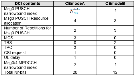
The same ten field names in both modes, and four of them given zero width in CE mode B. The totals at the foot are what the grant has to fit into.
Four rows collapse to zero in CE mode B : MCS, TPC, CSI request and UL delay all disappear, which is the twelve bit budget being paid for.Two rows are wider in CE mode B : the Msg3 PUSCH repetition count grows to three bits, and TBS appears at two bits where CE mode A has none.One entry is an expression rather than a number : the CE mode A Msg3 PUSCH narrowband index is NNBindex, which depends on the system bandwidth.The Zero padding row is missing from this screenshot : 36.213 has one between Msg3/4 MPDCCH narrowband index and Total Nr-bits. It carries 4 minus NNBindex for CE mode A and 0 for CE mode B, and without it the CE mode A column does not reach 20.
Checked against 36.213 v19.4.0, every value in the screenshot matches the current table. Only the padding row is absent, and adding it back makes the CE mode A column sum to 20 for any system bandwidth.
One further caveat belongs beside the screenshot. When higher layers indicate Early Data Transmission, 36.213 replaces this table with Table 6.2-F. The MCS and TBS rows disappear altogether there, and the CE mode A resource allocation widens from four bits to five. The totals stay at 20 and 12.
CE Mode A and CE Mode B side by side
The two sections above describe each mode on its own terms, and the differences are easier to hold in one place. Everything below is FDD, and every row is a value a reader will meet somewhere else on this handbook, so the table doubles as an index into the rest of it.
What differs | CE Mode A | CE Mode B |
Coverage enhancement level | 0 and 1 | 2 and 3 |
Uplink DCI format | 6-0A, with a TPC field | 6-0B, with no TPC field |
Downlink DCI format | 6-1A, with a TPC field | 6-1B, with no TPC field |
Power control | Legacy power control applies, and the power holds steady across a repetition period | Transmission is at maximum power and nothing adjusts it |
Repetition number field | 2 bits, so four levels | 3 bits, so eight levels |
PDSCH repetition ceiling | r16 or r32 | r192 to r2048 |
PUSCH repetition ceiling | r8, r16 or r32 | r192 to r2048 |
PUCCH repetition | r1, r2, r4 or r8 | r4, r8, r16 or r32 |
Msg3 repetition default | 8, when pusch-maxNumRepetitionCEmodeA-r13 is absent | 512, when pusch-maxNumRepetitionCEmodeB-r13 is absent |
Random access response grant | 20 bits | 12 bits |
HARQ processes, each direction | 8. Ten or fourteen with the later configurations | 2. Four with multi-TB scheduling configured |
Against 36.213 v19.4.0 and 36.331 v19.3.0. The PDSCH and PUSCH ceilings are the enumerations of the listings above, and the HARQ counts are from 36.213 clauses 7 and 8.0.
One row is worth pausing on, because it is the only overlap in the table. The PUCCH repetition sets share r4 and r8, so a cell can give both modes the same PUCCH repetition and the acknowledgement behaves identically. Every other row separates cleanly.
The pattern across the rest is consistent. CE mode A keeps a legacy mechanism and narrows its range, while CE mode B removes the mechanism and widens the range instead. Power control, modulation signalling and HARQ pipelining all follow that shape.
The mode changes what is signalled, not only how much is repeated : four fields of the random access response grant vanish in CE mode B rather than shrinking.The repetition ranges do not meet : CE mode A stops at 32 and CE mode B starts at 192, so there is no value both modes can be given.The PUCCH is the one shared range : r4 and r8 appear in both sets, and nothing else does.Every row is per cell and per mode at once : one SIB2 carries both columns, and the UE reads the one its mode selects.
What changed after Release 13
The two modes were defined in Release 13 and neither has been removed or renamed since. The field ce-Mode-r13 still carries exactly two values in 36.331 v19.3.0. What has changed is that almost every later addition attaches to one mode rather than to both, and the asymmetry of the table above has widened rather than closed.
The direction of travel is one sided. CE mode A has gained more HARQ processes, a second repetition scheme and a bundled acknowledgement, while CE mode B has gained multi transport block scheduling and little else. A network that wants the newer features is choosing CE mode A along with them.
Release | What was added | Which mode it reaches |
Rel-14 | Ten downlink HARQ processes, HARQ-ACK bundling in half duplex FDD, and a scheduling enhancement that can signal the PDSCH and HARQ-ACK delays | CE mode A |
Rel-14 | A fixed repetition set of 1, 2, 4, 8, 12, 16, 24 and 32 that replaces the repetition table, with the repetition number field widened from two bits to three | CE mode A, through ce-pdsch-pusch-EnhancementConfig-r14 |
Rel-15 | Sub-PRB uplink allocation, and an uplink HARQ-ACK on the MPDCCH that ends a PUSCH bundle early | Both, through ce-PUSCH-SubPRB-Config-r15 and mpdcch-UL-HARQ-ACK-FeedbackConfig-r15 |
Rel-16 | Several transport blocks from one grant, up to eight in CE mode A and up to four in CE mode B, which doubles the CE mode B HARQ process count | Both, through ce-PDSCH-MultiTB-Config-r16 and ce-PUSCH-MultiTB-Config-r16 |
Rel-17 | Fourteen downlink HARQ processes, with a HARQ-ACK delay configuration of its own | CE mode A, through ce-PDSCH-14HARQ-Config-r17 |
Compared against 36.331 v19.3.0 and 36.213 v19.4.0, with each release dated by the suffix of the field that configures it in 36.331.
One addition changes a number on this page rather than adding a feature beside it. Multi transport block scheduling takes the CE mode B HARQ process count from two to four in each direction. That is the only row of the comparison table a later release has moved.
The two modes are unchanged in name and in count : ce-Mode-r13 still offers ce-ModeA and ce-ModeB and nothing else.Most additions reach CE mode A only : the extra HARQ processes, the bundled acknowledgement and the fixed repetition set are all CE mode A features.CE mode B gained multi transport block scheduling : that is what raises its HARQ process count from two to four.The gap between the modes has widened : every row of the table above that moved, moved in favour of CE mode A.
Reference
[1] 3GPP TS 36.211 V13.2.0 (2016-06)
[2] 3GPP TS 36.213 V13.2.0 (2016-06)
[3] 4G, LTE-Advanced Pro and The Road to 5G by By Erik Dahlman, Stefan Parkvall, Johan Skold
[4] 3GPP R1-156979 : TSG RAN WG1 Meeting #83 - On CE Mode Capability of eMTC
[5] 3GPP TS 36.213 v19.4.0 - clause 6.2 Random Access Response Grant with Table 6-2, clause 7 for the downlink HARQ process counts, clause 8.0 for the uplink counts
[6] 3GPP TS 36.331 v19.3.0 - the ce-Mode-r13 field of PhysicalConfigDedicated, and the PDSCH-ConfigCommon-v1310, PUSCH-ConfigCommon-v1310 and PUCCH-ConfigDedicated-r13 information elements
[7] 3GPP TS 36.321 v19.3.0 - clause 5.1.1 for how a UE selects its coverage enhancement level