MPDCCH stands for MTC physical downlink control channel. It is a special type of PDCCH designed for bandwidth-reduced operation. According to 36.300 - 5.1.3, MPDCCH has following characteristics :
- MPDCCH is very similar to EPDCCH (You may think of MPDCCH as LTE-M1 version of EPDCCH)
- MPDCCH carries common and UE-specific signalling.
- MPDCCH can be transmitted single time or transmitted with the repetition (the number of repetition is configured by higher layer signaling message)
- Several different IEs in RRC message configures the number of MPDCCH repetition depending on the application of the MPDCCH as listed below.
- mpdcch-NumRepetition
- mpdcch-NumRepetition-RA
- mpdcch-NumRepetition-Paging
- Multiple MPDCCHs are supported and a UE monitors a set of MPDCCHs.
- MPDCCHs are formed by aggregation of enhanced control channel elements(eCCE), each eCCE consisting of a set of resource elements.
- Different code rates for MPDCCHs are realized by aggregating different numbers of eCCE.
- An MPDCCH can use either localized or distributed transmission
- MPDCCH supports RA-RNTI, SI-RNTI, P-RNTI, C-RNTI, Temporary C-RNTI and SPS C-RNTI.
Followings are the list of topics that help you understand
- ECCEs for MPDCCH
- MPDCCH Format
- Where does the UE look for MPDCCH ?
- DCI format for BL Operation
- Tables and Figures for Parameter Details
- Uplink Resource Block Assignment bits
- Downlink Resource Block Assignment bits
- Number of bits for Downlink Assignment Index
- Number of bits for TPMI information
- What changed in the DCI formats after Release 13
- Reference
ECCEs for MPDCCH
As a group of CCE is used to carry a PDCCH and a group of ECCE is used to carry EPDCCH, a group of ECCE is used to carry MPDCCH as well. (Refer to eREG to RE Mapping for ECCE structure). Number of ECCEs required to carry a MPDCCH varies depending on cases as follows :
Case 1 : FDD or TDD CE ModeA with No Repetition (Same as in EPDCCH)
< 36.211 Table 6.8A.1-1: Number of EREGs per ECCE >

Case 2 : TDD CE ModeA with Repetition
< 36.211 Table 6.8B.1-1: Number of EREGs per ECCE for frame structure type 2 >

Both tables answer with 4 or 8, and nothing else : an ECCE is either four EREGs or eight, and which one applies is decided by the cyclic prefix and the subframe type rather than by anything the network configures.In 36.211 Table 6.8A.1-1 the 4 covers two columns, not three : a normal subframe and special subframe configurations 3, 4 and 8 get 4 with normal cyclic prefix. Configurations 1, 2, 6, 7, 9 and 10 get 8, and so does every extended cyclic prefix case.36.211 Table 6.8B.1-1 has one column fewer : once repetition is configured, special subframe configurations 1, 2, 6, 7, 9 and 10 leave the table. Only a normal subframe and configurations 3, 4 and 8 remain on the normal cyclic prefix side.
The number matters because a PRB pair always holds 16 EREGs. Four EREGs per ECCE therefore gives 4 ECCEs in a PRB pair, and eight gives 2. That is the supply the aggregation levels in the next section draw on, and it halves the moment the subframe or the cyclic prefix moves into the second group.
Notice also which table applies when. 36.211 Table 6.8A.1-1 is the EPDCCH table, and MPDCCH borrows it whenever repetition is not configured. 36.211 Table 6.8B.1-1 is the MPDCCH table proper, and it only exists for frame structure type 2. So the page's two cases are really one table used twice and one table of its own.
16 EREGs per PRB pair is the fixed quantity : the EREGs per ECCE changes, the pair does not, so the ECCEs available per PRB pair are 4 or 2.Repetition removes subframe types rather than changing the count : Table 6.8B.1-1 keeps the same values of 4 and 8 and simply drops the configurations MPDCCH does not use.The eREG structure itself is unchanged from EPDCCH : the mapping of EREGs onto resource elements is the one 36.211 6.2.4A already defined, which is why this section can point at the EPDCCH page for it.
MPDCCH Format
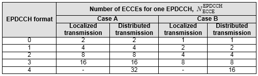
As there are multiple different PDCCH format in legacy LTE, there are several different EPDCCH/MPDCCH formats for LTE-M1. Depending on a couple of factors, one of two different sets of EPDCCH/MPDCCH formats are used. Number of ECCEs for each EPDCCH/MPDCCH are slightly different between the two sets.
Case 1 : MPDCCH associated with 2 or 4 PRBs, No Repetition.
< 36.211 Table 6.8A.1-2: Supported EPDCCH formats >
Case 2 : MPDCCH associated with 2 or 4 PRBs, Repetition
< 36.211 Table 6.8B.1-2: Supported MPDCCH formats >
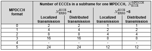
The MPDCCH table is keyed differently from the EPDCCH one : 36.211 Table 6.8A.1-2 splits its columns into Case A and Case B. 36.211 Table 6.8B.1-2 splits them by the number of EREGs per ECCE instead, 4 or 8, which the previous section just settled.MPDCCH format 4 exists in the table and carries nothing : all four of its cells are dashes, so the aggregation levels actually available are 1, 2, 4, 8 and 16 depending on the column.MPDCCH format 5 has no EPDCCH counterpart : it is 24 ECCEs with 4 EREGs per ECCE and 12 with 8, and it is the format the 2+4 PRB set uses.Localized and distributed always give the same count : in both tables the two columns of a pair hold identical numbers, so the transmission type changes where the ECCEs sit and not how many of them a format needs.
Format 5 is worth remembering, because it does not appear anywhere in the DCI tables further down. It belongs to the common search spaces that use a 2+4 PRB set rather than a plain 2 or 4. The next section is where that set comes from.
An MPDCCH format is an aggregation level, not a payload : it fixes how many ECCEs the channel occupies, and the DCI format decides what the bits mean.The usable range depends on the EREGs per ECCE : the 4 column reaches 16 ECCEs at format 3, and the 8 column reaches only 8, because the PRB pair has half as many ECCEs to give.
Where does the UE look for MPDCCH ?
Knowing how many ECCEs a format needs still leaves the harder question open. The UE has to find the channel before it can decode it, and MPDCCH is not where PDCCH was. It does not span the carrier, so there is no single region to sweep. 36.213 9.1.5 answers this with a narrowband, a PRB set and six search spaces.
The network gives the UE one or two MPDCCH-PRB-sets, exactly as it gives an EPDCCH UE one or two EPDCCH-PRB-sets. Each set is configured on its own for localized or distributed transmission. What is new is that the set sits inside a narrowband rather than anywhere on the carrier. The narrowband in force for a given subframe is itself determined by rule rather than by a grant.
Figure 1. The six search spaces and what each one carries. Only the UE-specific space carries ordinary unicast grants; the other five exist so that a UE with no dedicated configuration can still be reached.
Two of those boxes deserve a second look. Type0 is the odd one. It carries C-RNTI and SPS C-RNTI candidates the way the UE-specific space does, and a UE configured with CEModeB does not monitor it unless ce-ETWS-CMAS-RxInConn is configured. Type1A and Type2A came later, for SC-PTM, and the specification spends several sentences telling the UE when not to monitor them.
Type1A is also where MPDCCH format 5 is actually used. For the Type1 and Type1A common search spaces the MPDCCH-PRB-set is 2+4 PRB pairs rather than a plain 2 or 4, and a 24 ECCE candidate is what that set supports. The MPDCCH format table lists format 5 for exactly this reason.
The candidate counts come from four tables rather than one. 36.213 Tables 9.1.5-1a and 9.1.5-1b cover CEModeA, for a 2 or 4 PRB set and for a 2+4 PRB set, and 36.213 Tables 9.1.5-2a and 9.1.5-2b do the same for CEModeB. On top of the aggregation level there is a repetition level, taken from 36.213 Table 9.1.5-3, and each search space substitutes its own higher layer parameter into it.
Five common search spaces, one UE-specific : Type0, Type1, Type1A, Type2 and Type2A are common, and only the UE-specific space is derived per UE.Each common space brings its own repetition parameter : paging uses mPDCCH-NumRepetition-Paging, random access uses mPDCCH-NumRepetition-RA, and SC-MTCH uses mpdcch-NumRepetitions-SC-MTCH.A UE is never asked to monitor two of them at once : 36.213 9.1.5 releases the UE from monitoring the UE-specific space together with Type1, and from monitoring it together with Type2.The 2+4 PRB set is the reason format 5 exists : Type1 and Type1A use that set, and 24 ECCEs is the candidate size it supports.A non-BL/CE UE never monitors MPDCCH : 36.213 9.1.5 says so outright, which is the mirror of the rule that a BL/CE UE never monitors EPDCCH.
DCI format for BL Operation
We use special DCI formats for BL Operations. At high level operation, the function of these new DCIs are similar to DCIs for legacy LTE. There is slight differences in terms of details.
Two things organise that list. The first is the flag bit. Formats 6-0A and 6-1A share one payload size, and a single leading flag tells them apart. Formats 6-0B and 6-1B do the same. So a UE decoding a candidate never has to try two sizes where one will do.
The second is the coverage enhancement mode. The A formats belong to CE mode A and the B formats to CE mode B, and a UE is configured in one mode at a time. So in any given moment a UE is looking for 6-0A and 6-1A, or for 6-0B and 6-1B, and never for all four.
Format 6-2 stands outside both pairings. It carries paging and direct indication, both of which reach a UE that has no dedicated configuration, so it travels in a common search space rather than the UE-specific one.
DCI format |
CE mode |
What it schedules |
Paired with |
6-0A | A | PUSCH, the uplink grant | 6-1A |
6-0B | B | PUSCH, the uplink grant | 6-1B |
6-1A | A | PDSCH, and a random access procedure ordered by the network | 6-0A |
6-1B | B | PDSCH | 6-0B |
6-2 | A or B | Paging, and direct indication | - |
The five DCI formats of LTE-M1. The pairing column is the one worth remembering, because it is what lets a UE decode a candidate once rather than twice.
The flag bit is the first bit of the payload : value 0 means the uplink format of the pair and value 1 means the downlink one, so the two share a size on purpose.CE mode picks the pair, not the network per grant : a UE configured with CE mode A never looks for 6-0B or 6-1B.Format 6-2 is the only one a UE reads before it is configured : paging and direct indication have to reach a UE with no dedicated setup.
Format 6-0A
This is the uplink grant for a UE in CE mode A, and it is the larger of the two uplink formats. The table below is the Release 13 field list, split into an FDD and a TDD version, because the two differ in a handful of rows rather than in structure.
This is to schedule PUSCH (i.e, UL Grant). It has the same role as DCI Format 0 in legacy LTE.
Followings are the summary of the DCI contents based on 36.212 V13.2.0 (2016-06) - 5.3.3.1.10
< Format 6-0A for FDD >
|
Field |
# of Bits |
Description |
|
Flag for format 6-0A/format 6-1A differentiation |
1 |
0 - 6-0A, 1 - 6-1A |
|
Frequency Hopping flag |
1 |
|
|
Resource Block assignment |
5+ (Variable) |
- (Variable) is defined in Uplink RB Assignment bits - 5 Bits indicate RIV in RA Type 2 |
|
Modulation Coding Scheme |
4 |
|
|
Repetition Number |
2 |
|
|
HARQ Process Number |
3 |
|
|
New Data Indicator |
1 |
|
|
Redundancy Version |
2 |
|
|
TPC Command for scheduled PUSCH |
2 |
|
CSI Request |
1 |
|
SRS Request |
1 |
|
DCI subframe repetition number |
2 |
< Format 6-0A for TDD >
|
Field |
# of Bits |
Description |
|
Flag for format 6-0A/format 6-1A differentiation |
1 |
0 - 6-0A, 1 - 6-1A |
|
Frequency Hopping flag |
1 |
|
|
Resource Block assignment |
5+ (Variable) |
- (Variable) is defined in Uplink RB Assignment bits - 5 Bits indicate RIV in RA Type 2 |
|
Modulation Coding Scheme |
4 |
|
|
Repetition Number |
2 |
|
|
HARQ Process Number |
3 |
|
|
New Data Indicator |
1 |
|
|
Redundancy Version |
2 |
|
|
TPC Command for scheduled PUSCH |
2 |
|
UL Index |
2 |
|
Downlink Assignment Index |
2 |
|
CSI Request |
1 |
|
SRS Request |
1 |
|
DCI subframe repetition number |
2 |
Format 6-0B
CE mode B trades granularity for reach, and the field list is where that shows. Compare this table with the one for 6-0A above. Most of the differences are fields that have gone, but not all of them, and the one that grew is the interesting one.
This is to schedule PUSCH (i.e, UL Grant). It has the same role as DCI Format 0 in legacy LTE.
Followings are the summary of the DCI contents based on 36.212 V13.2.0 (2016-06) - 5.3.3.1.11
|
Field |
# of Bits |
Description |
|
Flag for format 6-0B/format 6-1B differentiation |
1 |
0 - 6-0B, 1 - 6-1B |
|
Resource Block assignment |
3+ (Variable) |
|
|
Modulation Coding Scheme |
4 |
|
|
Repetition Number |
3 |
|
|
HARQ Process Number |
1 |
|
|
New Data Indicator |
1 |
|
DCI subframe repetition number |
2 |
Seven fields against the twelve of 6-0A for FDD, and the arithmetic of the cut is worth reading off directly.
Field |
6-0A, FDD |
6-0B |
What the change means |
Frequency Hopping flag | 1 | - | Hopping is not offered in CE mode B |
Resource Block assignment | 5 + variable | 3 + variable | A coarser allocation inside the narrowband |
Repetition Number | 2 | 3 | Eight repetition values instead of four, which is the whole point of CE mode B |
HARQ Process Number | 3 | 1 | Two processes instead of eight |
Redundancy Version | 2 | - | No redundancy version is signalled |
TPC Command for scheduled PUSCH | 2 | - | No closed loop power control on this grant |
CSI Request | 1 | - | No aperiodic CSI is requested |
SRS Request | 1 | - | No aperiodic SRS is requested |
The two uplink grants side by side, from the field lists on this page. Five fields disappear and two get narrower, while Repetition Number is the one field that grows.
Read that last row against the rest and the design becomes clear. A UE in CE mode B is far enough down that fine control is pointless, so power control, redundancy version, CSI and SRS all go. The bits saved are not simply dropped, though. One of them goes back into Repetition Number, which widens from two bits to three and so doubles the number of repetition levels the network can order.
The HARQ process count follows the same reasoning from the other direction. With repetition running into hundreds of subframes, a transmission occupies the channel long enough that eight parallel processes have nothing to do, so one bit and two processes is enough.
Five fields go and two shrink : frequency hopping, redundancy version, the TPC command, the CSI request and the SRS request are all absent, and the resource block assignment and HARQ process number are narrower.Repetition Number is the field that grows : three bits instead of two, so eight repetition levels instead of four.Two HARQ processes are enough here : a heavily repeated transmission holds the channel long enough that more would never be used.The flag still pairs it with 6-1B : the payload size matches its downlink partner, exactly as 6-0A matches 6-1A.
Format 6-1A
This is the busiest of the five formats. It carries ordinary downlink grants, and it also carries the network's order to start a random access procedure, which is why the tables below come in several variants rather than one.
This is used for following purpose :
- to schedule PDSCH.
- to schedule Random Access Procedure initiated by a PDCCH Order
Followings are the summary of the DCI contents based on 36.212 V13.2.0 (2016-06) - 5.3.3.1.12
< For User Data - FDD, CRC scrambled by C-RNTI >
|
Field |
# of Bits |
Description |
|
Flag for format 6-0A/format 6-1A differentiation |
1 |
0 - 6-0A, 1 - 6-1A |
|
Frequency Hopping flag |
1 |
|
|
Resource Block assignment |
5+ (Variable) |
- (Variable) is defined in Downlink RB Assignment bits - 5 Bits indicate RIV in RA Type 2 |
|
Modulation Coding Scheme |
4 |
|
|
Repetition Number |
2 |
|
|
HARQ Process Number |
3 |
|
|
New Data Indicator |
1 |
|
|
Redundancy Version |
2 |
|
|
TPC Command for scheduled PUCCH |
2 |
|
Downlink Assignment Index |
4 or 2 or 0 |
|
Antenna Port(s) and Scrambling Identity |
2 |
|
TMPI information for precoding |
2 or 4 |
|
PMI configuration for precoding |
1 |
|
HARQ-ACK resource offset |
2 |
|
DCI subframe repetition number |
2 |
< For User Data - TDD, CRC scrambled by C-RNTI >
|
Field |
# of Bits |
Description |
|
Flag for format 6-0A/format 6-1A differentiation |
1 |
0 - 6-0A, 1 - 6-1A |
|
Frequency Hopping flag |
1 |
|
|
Resource Block assignment |
5+ (Variable) |
- (Variable) is defined in Downlink RB Assignment bits - 5 Bits indicate RIV in RA Type 2 |
|
Modulation Coding Scheme |
4 |
|
|
Repetition Number |
2 |
|
|
HARQ Process Number |
4 |
|
|
New Data Indicator |
1 |
|
|
Redundancy Version |
2 |
|
|
TPC Command for scheduled PUCCH |
2 |
|
Downlink Assignment Index |
4 or 2 or 0 |
|
Antenna Port(s) and Scrambling Identity |
2 |
|
TMPI information for precoding |
2 or 4 |
|
PMI configuration for precoding |
1 |
|
HARQ-ACK resource offset |
2 |
|
DCI subframe repetition number |
2 |
< For Scheduling Random Access Procedure, CRC scrambled by C-RNTI >
|
Field |
# of Bits |
Description |
|
Flag for format 6-0A/format 6-1A differentiation |
1 |
0 - 6-0A, 1 - 6-1A |
|
Frequency Hopping flag |
1 |
|
|
Resource Block assignment |
5+ (Variable) |
- (Variable) is defined in Downlink RB Assignment bits - 5 Bits indicate RIV in RA Type 2 |
|
Preamble Index |
6 |
|
|
PRACH Mask Index |
4 |
|
|
Starting CE Level |
2 |
See CE Level |
|
All Remaining Bits |
|
Set to be 0 |
< For User Data - FDD, CRC scrambled by RA-RNTI >
|
Field |
# of Bits |
Description |
|
Flag for format 6-0A/format 6-1A differentiation |
1 |
0 - 6-0A, 1 - 6-1A |
|
Frequency Hopping flag |
1 |
|
|
Resource Block assignment |
5+ (Variable) |
- (Variable) is defined in Downlink RB Assignment bits - 5 Bits indicate RIV in RA Type 2 |
|
Modulation Coding Scheme |
4 |
|
|
Repetition Number |
2 |
|
|
HARQ Process Number |
3 |
Reserved |
|
New Data Indicator |
1 |
Reserved |
|
Redundancy Version |
2 |
|
|
TPC Command for scheduled PUCCH |
2 |
|
Downlink Assignment Index |
4 or 2 or 0 |
Reserved |
Antenna Port(s) and Scrambling Identity |
2 |
|
TMPI information for precoding |
2 or 4 |
|
PMI configuration for precoding |
1 |
|
HARQ-ACK resource offset |
2 |
Reserved |
DCI subframe repetition number |
2 |
< For User Data - TDD, CRC scrambled by C-RNTI >
|
Field |
# of Bits |
Description |
|
Flag for format 6-0A/format 6-1A differentiation |
1 |
0 - 6-0A, 1 - 6-1A |
|
Frequency Hopping flag |
1 |
|
|
Resource Block assignment |
5+ (Variable) |
- (Variable) is defined in Downlink RB Assignment bits - 5 Bits indicate RIV in RA Type 2 |
|
Modulation Coding Scheme |
4 |
|
|
Repetition Number |
2 |
|
|
HARQ Process Number |
4 |
Reserved |
|
New Data Indicator |
1 |
Reserved |
|
Redundancy Version |
2 |
|
|
TPC Command for scheduled PUCCH |
2 |
|
Downlink Assignment Index |
4 or 2 or 0 |
Reserved |
Antenna Port(s) and Scrambling Identity |
2 |
|
TMPI information for precoding |
2 or 4 |
|
PMI configuration for precoding |
1 |
|
HARQ-ACK resource offset |
2 |
Reserved |
DCI subframe repetition number |
2 |
Format 6-1B
This is the CE mode B downlink grant, and it is the shortest table on the page. Read it against 6-1A rather than on its own, because what is missing from it is the point.
This is used to schedule PDSCH
Followings are the summary of the DCI contents based on 36.212 V13.2.0 (2016-06) - 5.3.3.1.13
< For User Data - CRC scrambled by C-RNTI >
|
Field |
# of Bits |
Description |
|
Flag for format 6-0B/format 6-1B differentiation |
1 |
0 - 6-0B, 1 - 6-1B |
|
Modulation Coding Scheme |
4 |
|
|
Resource Block assignment |
1+ (Variable) |
- (Variable) is defined in Downlink RB Assignment bits - 1 bit 0 : Assign PRB 0,1,2,3 1 : Assign full 6 RB |
|
Repetition Number |
3 |
|
|
HARQ Process Number |
1 |
|
|
New Data Indicator |
1 |
|
HARQ-ACK resource offset |
2 |
|
DCI subframe repetition number |
2 |
< For Scheduling Random Access Procedure, CRC scrambled by C-RNTI >
|
Field |
# of Bits |
Description |
|
Flag for format 6-0B/format 6-1B differentiation |
1 |
0 - 6-0B, 1 - 6-1B |
|
Reserved bits |
2+ (Variable) |
|
|
Preamble Index |
6 |
|
|
PRACH Mask Index |
4 |
|
|
Starting CE Level |
2 |
See CE Level |
|
All Remaining Bits |
|
Set to be 0 |
< For User Data, CRC scrambled by RA-RNTI >
|
Field |
# of Bits |
Description |
|
Flag for format 6-0B/format 6-1B differentiation |
1 |
0 - 6-0B, 1 - 6-1B |
|
Modulation Coding Scheme |
4 |
|
|
Resource Block assignment |
1+ (Variable) |
- (Variable) is defined in Downlink RB Assignment bits - 1 bit 0 : Assign PRB 0,1,2,3 1 : Assign full 6 RB |
|
Repetition Number |
3 |
|
|
HARQ Process Number |
1 |
Reserved |
|
New Data Indicator |
1 |
Reserved |
HARQ-ACK resource offset |
2 |
Reserved |
DCI subframe repetition number |
2 |
Format 6-2
Paging and direct indication share one format and one payload size, and a single flag separates them. That matters for a UE in idle mode, which wakes, decodes one candidate, and has to learn from the first bit whether a page or a system information change is arriving.
This is used to schedule Paging and Direct Indication
Followings are the summary of the DCI contents based on 36.212 V13.2.0 (2016-06) - 5.3.3.1.14
< When Flag = 0 , Direct Indication>
|
Field |
# of Bits |
Description |
|
Flag for paging/direct indication differentiation |
1 |
0 - direct indication, 1 - paging |
|
Direct Indication Information |
8 |
|
|
Reserved for all remaining bits |
|
< When Flag = 1 , Paging>
|
Field |
# of Bits |
Description |
|
Flag for paging/direct indication differentiation |
1 |
0 - direct indication, 1 - paging |
|
Resource Block assignment |
(Variable) |
|
|
Modulation and Coding Scheme |
3 |
|
|
Repetition Number |
3 |
|
DCI subframe repetition number |
2 |
The two tables have to end up the same length, and that is what the Reserved row in the first one is doing. 36.212 pads the direct indication branch with reserved bits until it matches the size of the paging branch. A UE therefore decodes one candidate of one size, and only then reads the flag to find out which of the two arrived.
That single flag decides a great deal. With value 1 the rest of the payload is an ordinary downlink grant. It carries a narrowband index, a three bit modulation and coding scheme, a repetition number and the subframe repetition number. The PDSCH it points at is where the paging message arrives. With value 0 there is no grant at all, and the eight bits of direct indication are the entire message.
Direct indication exists so that a system information change does not need a PDSCH. The network can tell an idle UE that something has changed using nothing but the MPDCCH payload. For a UE that wakes briefly and sleeps again, that is the cheapest signal available.
Both branches share one payload size : reserved bits pad the direct indication branch, so blind decoding cost does not double.The flag is read after decoding, not before : the UE cannot know which branch it has until the candidate decodes, which is why the sizes must match.Paging still costs a PDSCH : the paging branch is a grant, and the paging message itself arrives on the PDSCH it schedules.Direct indication costs nothing beyond the MPDCCH : eight bits in the DCI carry the notification on their own.Format 6-2 is not paired with anything : it has no uplink partner, so its flag separates two downlink meanings rather than two directions.
Tables and Figures for Parameter Details
Several rows in the tables above give a bit width as a formula rather than a number, because the width follows the system bandwidth. The tables collected here are the ones those rows point at, so this section is a lookup rather than an argument.
Uplink Resource Block Assignment bits
The number of bits for MSB part of Uplink Resource Block assignment is determined by following table. As shown here, the bit length varies depending on system bandwidth. Actually this bit length is the one that is required to represents all the narrowband index for each system bandwidth.
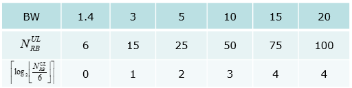
The bottom row is the field width : it runs 0, 1, 2, 3, 4, 4 across the six bandwidths, so a 1.4 MHz cell spends no bits at all on the narrowband index.15 MHz and 20 MHz both land on 4 : 75 resource blocks give 12 narrowbands and 100 give 16, and both need the same four bits.This is the MSB part only : the bits below it carry the allocation inside the chosen narrowband, which is why the tables above write the field as a sum.
Downlink Resource Block Assignment bits
The number of bits for MSB part of Downlink Resource Block assignment is determined by following table. As shown here, the bit length varies depending on system bandwidth. Actually this bit length is the one that is required to represents all the narrowband index for each system bandwidth.
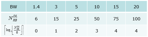
The downlink table holds the same six columns and the same six widths, which is the useful result rather than a coincidence. A narrowband is six resource blocks in either direction, so the count of narrowbands and the bits needed to index them come out the same on both sides of the link.
Uplink and downlink agree row for row : the same bandwidth gives the same number of narrowbands and the same index width, so one table would have done for both.A 1.4 MHz cell has exactly one narrowband : there is nothing to index, so the field disappears rather than shrinking to one bit.
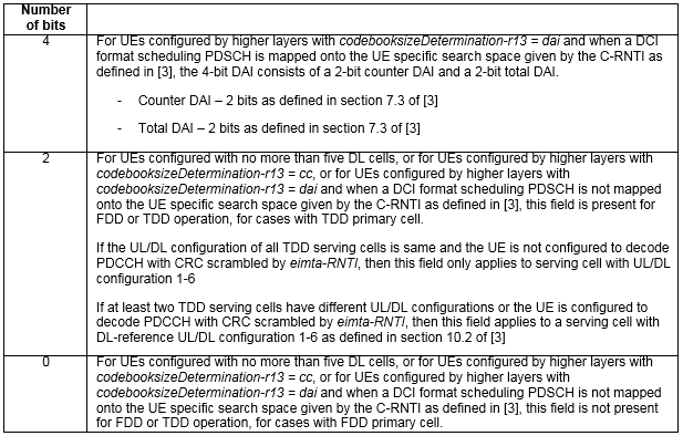
< 36.212-Table 5.3.3.1.2-2: Number of bits for Downlink Assignment Index. >
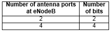
< 36.212-Table 5.3.3.1.3A-1: Number of bits for TPMI information. >
What changed in the DCI formats after Release 13
Every table on this page is stamped 36.212 V13.2.0, and that stamp matters. The five formats were defined in Release 13 and none of them has been replaced, but all of them have grown. A field list captured in 2016 is still a correct Release 13 list, and it is no longer the whole list.
The clause numbers have not moved, which makes checking easy. Formats 6-0A through 6-2 still live in 36.212 clauses 5.3.3.1.10 to 5.3.3.1.14, so the references above still point at the right clauses. What has changed is what those clauses contain.
The most visible growth is in 6-0A. Release 13 gave it one way to describe an uplink allocation, and the current clause gives it four. A Number of resource units field arrives when ce-PUSCH-SubPRB-Config is configured, and it says whether the grant uses whole resource blocks or a sub-PRB allocation. The resource block assignment then branches on that, and again on whether a flexible starting PRB is enabled.
Preconfigured uplink resources added a second branch to the same format. When the CRC is scrambled by PUR-RNTI and the resource block assignment is all ones, the rest of the payload means something else. It becomes an ACK or fallback indicator, a PUSCH repetition adjustment and a timing advance adjustment. That is a different message in the same bits, and no Release 13 table shows it.
Two fields also became variable in width. Modulation and coding scheme is 3 or 4 bits, and the shorter form goes with a sub-PRB allocation. Repetition number is 2 or 3 bits, and the longer form arrives when ce-pdsch-puschEnhancement-config is configured. A decoder that assumes the Release 13 widths will misread both.
Format |
What the current clause adds beyond Release 13 |
6-0A | Sub-PRB uplink allocation, with a Number of resource units field and a 3-bit modulation and coding scheme. A flexible starting PRB branch. A preconfigured uplink resource branch under PUR-RNTI, carrying an ACK or fallback indicator, a PUSCH repetition adjustment and a timing advance adjustment. Repetition number widened to 3 bits in one case |
6-0B | Sub-PRB uplink allocation reaches CE mode B as well, under the same higher layer configuration |
6-1A | Also used for notifying an SC-MCCH change and for preconfigured uplink resources. A direct indication branch when the CRC is scrambled by SI-RNTI and ce-ETWS-CMAS-RxInConn is configured, carrying 8 bits of direct indication. A Starting CE level field in the random access order branch |
6-1B | Allocation rules extended for a 20 MHz maximum PDSCH bandwidth in CE mode B |
6-2 | Also used for scheduling a PDSCH carrying SC-MCCH, with an SC-RNTI branch carrying a 1-bit SC-MCCH change notification |
Compared against 36.212 v19.3.0. Every row is an addition rather than a replacement, so the Release 13 field lists above remain correct for a Release 13 network.
None of this makes the tables above wrong. A Release 13 UE on a Release 13 network sees exactly the fields they list, and most of the additions only appear when a specific higher layer parameter is configured. The tables are simply no longer complete. Before trusting a bit count, check which of those parameters the network has sent.
The clause numbers still hold : 5.3.3.1.10 to 5.3.3.1.14 are the same clauses they were in Release 13, so only the contents need re-reading.Most additions are conditional : a field such as Number of resource units appears only when its higher layer parameter is configured, which is why a live decode can still match the Release 13 list exactly.Two field widths became variable : modulation and coding scheme at 3 or 4 bits and repetition number at 2 or 3, and a fixed-width decoder gets both wrong.6-0A carries a second message now : under PUR-RNTI with an all-ones resource block assignment, the remaining bits mean something else entirely.SC-PTM reached 6-1A and 6-2 : both formats gained SC-MCCH duties, which is the same feature that added the Type1A and Type2A search spaces.
Reference
The specifications the tables on this page are taken from, and the versions they were checked against.
[1] 3GPP TS 36.211 V13.2.0 (2016-06)
[3] 3GPP TS 36.211 v19.3.0 - clause 6.8A.1 and clause 6.8B.1, with Tables 6.8A.1-1, 6.8A.1-2, 6.8B.1-1 and 6.8B.1-2
[4] 3GPP TS 36.212 v19.3.0 - clauses 5.3.3.1.10 to 5.3.3.1.14, the current field lists for DCI formats 6-0A, 6-0B, 6-1A, 6-1B and 6-2
[5] 3GPP TS 36.213 v19.4.0 - clause 9.1.5 MPDCCH assignment procedure, with Tables 9.1.5-1a to 9.1.5-4