Scheduling is the process of allocating resources for transmitting data. As in LTE (actually in all cellular communication), NR scheduling is dictated by Network and UE is just following what network tells. Overall scheduling mechanism in NR is pretty much similar to LTE scheduling, but NR has finer granularity than LTE especially in terms of time domain scheduling at physicallayer. In this page, I will just go through very high level view of NR scheduling process. For the detailed procedure/operation, I will create separate pages and point to those pages.
- High Level Factors for Scheduling
- Scheduling Structure at PHY Layer
- Type of Downlink Scheduling
- Types for Uplink Scheduling
- RNTI used in Scheduling
- YouTube
High Level Factors for Scheduling
At high level view, NR Scheduling is not much different from LTE scheduling in terms of overall concept. In this page, I will describe on the overview of NR Scheduling and the further details will be linked to several separate pages. The overall skelleton of this page is based on Based on "38.300 - 10 Scheduling" even though most part is written in my own words and illustrations.

Real Life Example : srsRAN Scheduler
How to implement the scheduler is up to specific implementation of the product. In other words, it is not defined by 3GPP. and almost no eNB/gNB vendors release the details of the scheduler. This high level description of the scheduler of srsRAN gNB which are presented by one of the workshop presentation. This would be a rare chance to take a look into the picture of the scheduler which are implemented in a real product.
The scheduler uses real-time inputs to make precise decisions about resource allocation, ensuring efficient use of spectrum and maintaining quality of service across both control signaling and data transmission.
The following diagram represents the interaction between various components and the scheduler (depicted as "SCHED") in the architecture,
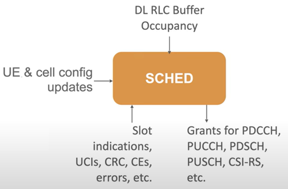
Image Source : 2024 srsRAN Fall Workshop: An Introduction to the srsRAN DU-High
Followings are breakdown and brief descriptions of the diagram
-
Inputs to the Scheduler: -
DL RLC Buffer Occupancy: Provides information about the downlink data waiting in buffers, helping prioritize resource allocation based on buffer levels.
-
Slot Indications: Includes feedback like uplink control indicators (UCIs), cyclic redundancy check results (CRC), control elements (CEs), and error reports, ensuring the scheduler stays synchronized with slot timing and network status.
-
UE & Cell Config Updates: Delivers updated configurations for user equipment (UE) and cells to align the scheduler's decisions with the latest network parameters.
-
Outputs from the Scheduler: -
Grants: Allocates resources for various channels and tasks, including:
-
PDCCH (Physical Downlink Control Channel)
-
PUCCH (Physical Uplink Control Channel)
-
PDSCH (Physical Downlink Shared Channel)
-
PUSCH (Physical Uplink Shared Channel)
-
CSI-RS (Channel State Information Reference Signals)
Thefollowing diagram illustrates the interactions between various components in the DU High architecture, focusing on the MAC layer and its communication with other layers like RLC, FAPI, and the DU Manager. It highlights the interdependent roles of each MAC component and their integration with other parts of the DU High architecture, ensuring efficient and real-time processing of uplink and downlink communications.
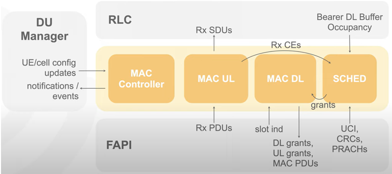
Image Source : 2024 srsRAN Fall Workshop: An Introduction to the srsRAN DU-High
Followings are breakdown and brief descriptions of the diagram
-
DU Manager: -
Acts as the central control point.
-
Sends UE and cell configuration updates along with notifications or events to the MAC layer.
-
MAC Layer Components: -
MAC Controller:
-
Manages configurations and coordinates actions between other MAC components.
-
Interfaces with the DU Manager to apply updates or handle events.
-
MAC UL (Uplink):
-
Processes received PDUs from the FAPI layer.
-
Decodes PDUs and passes SDUs to the RLC layer for further processing.
-
Handles uplink data transmission from UEs to the network.
-
MAC DL (Downlink):
-
Receives control elements (CEs) from the RLC layer.
-
Collaborates with the Scheduler to allocate downlink resources.
-
Uses Scheduler grants to handle downlink data transmissions efficiently.
-
Scheduler (SCHED):
-
Monitors bearer downlink buffer occupancy.
-
Allocates resources for downlink (DL), uplink (UL), and MAC PDUs.
-
Passes these grants to the FAPI layer.
FAPI Layer: -
Facilitates communication between the DU and the lower PHY layer.
-
Receives slot indications, uplink control indicators (UCIs), cyclic redundancy checks (CRCs), and PRACH messages.
-
Ensures real-time synchronization and efficient resource allocation.
The following diagram illustrates the intricate workings of the scheduling architecture in the DU High system, showing how different schedulers and components collaborate to allocate resources effectively.
The interaction between these components culminates in the Scheduler Decision, which provides the final resource allocation for both uplink and downlink communications. The architecture is designed to be modular and adaptive, allowing efficient handling of diverse scheduling tasks while maintaining high performance and low latency.
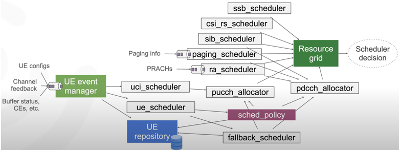
Image Source : 2024 srsRAN Fall Workshop: An Introduction to the srsRAN DU-High
Followings are breakdown and brief descriptons of the diagram
-
UE Event Manager: -
Central handler for processing inputs like UE configurations, channel feedback, buffer status, and control elements (CEs).
-
Manages events asynchronously to optimize resource handling.
UE Scheduler: -
Manages UE-specific tasks while ensuring sequential execution for each UE.
-
Coordinates with other schedulers and allocators.
-
Uses the UE Repository to store the state and context of each UE.
Resource Grid: -
Tracks spectrum resource usage.
-
Receives updates from specialized schedulers to ensure efficient allocation:
-
SSB Scheduler: Manages synchronization signal blocks.
-
CSI-RS Scheduler: Allocates channel state information reference signals.
-
SIB Scheduler: Handles system information blocks.
-
Paging Scheduler: Allocates resources for paging information.
-
RA Scheduler: Manages random access resources.
PUCCH and PDCCH Allocators: -
PUCCH Allocator: Allocates uplink control channels.
-
PDCCH Allocator: Allocates downlink control channels.
Sched Policy: -
Defines the scheduling policy, such as round-robin or proportional fairness, for resource allocation.
-
Ensures flexibility in adapting to different network needs.
Fallback Scheduler: -
Acts as a backup to handle critical tasks in case of scheduling delays or unexpected scenarios.
Scheduler Decision: -
Combines all inputs and allocations to finalize resource usage for uplink and downlink communications.
-
Ensures real-time and efficient scheduling based on network demands.
Following diagram illustrates the interaction between the PHY layer, MAC & Scheduler, and RLC in the process of resource allocation, scheduling, and data transmission within the DU High architecture.
It emphasizes the sequential and hierarchical interaction between layers, where each component plays a specific role in ensuring efficient scheduling, encoding, and transmission of both control and user data. The entire process is designed to meet the real-time requirements of the RAN system while maintaining flexibility and adaptability for various network scenarios.
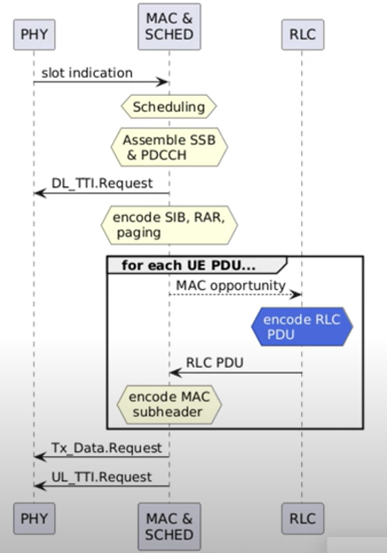
Image Source : 2024 srsRAN Fall Workshop: An Introduction to the srsRAN DU-High
Followings are breakdown and brief descriptons of the diagram
-
Slot Indication: -
The process begins with the PHY layer sending a slot indication to the MAC & Scheduler, signaling the start of a new time slot.
Scheduling: -
The MAC & Scheduler performs scheduling for the new slot, allocating resources for both downlink and uplink transmissions.
Control Channel Assembly: -
The scheduler assembles the SSB (Synchronization Signal Block) and PDCCH (Physical Downlink Control Channel) as part of the control signaling process.
DL_TTI.Request: -
A DL_TTI.Request is generated, containing scheduling information for downlink transmissions, such as:
-
SIB (System Information Blocks)
-
RAR (Random Access Response)
-
Paging information
UE-Specific PDU Processing: -
For each UE PDU:
-
The MAC layer creates opportunities for encoding.
-
RLC PDU is encoded, carrying data passed from the RLC layer.
-
A MAC subheader is constructed, containing metadata like logical channel IDs and lengths.
Uplink Data Handling: -
For uplink transmissions, the MAC & Scheduler generates a UL_TTI.Request, specifying uplink grants and expected transmissions.
-
A Tx_Data.Request is sent to the PHY layer, facilitating the uplink data transmission.
Layer Interaction: -
The diagram shows the interaction between layers (PHY, MAC & Scheduler, and RLC) to ensure the sequential processing of scheduling, resource allocation, and data transmission.
Real-Time Processing: -
The architecture ensures efficient real-time scheduling and transmission for both control and user data, meeting the stringent requirements of the RAN system.
Scheduling Structure at PHY Layer
In terms of Physical layer, there are roughly two categories of scheduling that are time domain scheduling and frequency domain scheduling. Frequency Domain Scheduling in NR is almost same as LTE. Time Domain Scheduling in NR is similar to LTE TDD schduling, but there are several time domain scheduling factors that are not supported in LTE.
Actually Scheduling is a huge part in NR protocol and there are so many factors and terminologies that you need to understand. Since it is difficult to put all those details in one page, I have written several different pages with the details for each individual aspect/factors listed below. Just try to get the big picture about the scheduling in this page and follow through the link mentioned in comments column in the following table.
|
Domain |
Factors/Parameters |
Comments |
|
Time |
TDD DL/UL CommonConfiguration |
In terms of concept, this is very similar to LTE TDD DL/UL configuration, but NR configuration provides more flexibility. For the details, refer to this page. |
|
TDD DL/UL DedicatedConfiguration |
In LTE, once a subframe is scheduled all the symbols in the subframe are used for data transmission. But in NR, it is possible to set only a few symbols in the subframe for data transmission and reception. It means in NR, symbol level scheduling is possible. TDD DL/UL Dedicated Configuration is one of mechanisms for symbol level scheduling. For the details, refer to this page. |
|
|
SlotFormat |
SlotFormat is also a kind of mechanism for symbol level scheduling. 3GPP defines 61 different type of symbol level scheduling type (i.e, SlotFormat). For the details, refer to this page. |
|
|
SLIV |
This is another kind of mechanism for symbol level scheduling for a slot. For the details, refer to this page. |
|
|
K0, K1, K2 |
In LTE TDD, there are simiar parameters like K1 and K2(K1 is similar to K in TDD LTE and K2 is similar to k in TDD LTE). But K1, K2 in NR has more flexibility. However, there is no parameters in LTE that is equivalent to K0. In other words, in LTE K0 is always 0, so we don't need to define this as a parameter. For the details of K0, K1, K2, refer to this page. |
|
|
Frequency |
RA Type |
This is similar to LTE RA Type. NR supports two RA Types - Type 0 (Bitmap) and Type 1(RIV). For the details of RA Types, refer to this page. |
|
RBG Size |
This is same concept as RBG size in LTE Resource Allocation Type 0. In LTE, RBG size can be 1,2,3,4 depending on channel bandwidth. Similarily in in NR the RBG size can only be 2,4,8 or 16 depending on the bandwidth of the BWP. But in NR, for the same BWP width, the RBG size varies depending on configuration type. For the details of RBG Size, refer to this page. |
Type of Downlink Scheduling
There are two types of scheduling for downlink. One is called 'Dynamic Scheduling' and the other one SPS(Semi Persistent Scheduling'). Dynamic scheduling is the mechanism in which each and every PDSCH is scheduled by DCI(DCI 1_0 or DCI 1_1). SPS is the mechanism in which the PDSCH transmission is scheduled by RRC message. SPS is explained in detail here.
Dynamic Scheduling requires monitoring the PDCCH for every PDSCH, providing flexibility but increasing overhead.SPS reduces PDCCH monitoring by preconfiguring periodic transmissions, improving efficiency for consistent traffic patterns but with less flexibility.

Dynamic Scheduling
Every transmission in this mode costs a control message as well as a data message. That pairing is the point of it, and it is also the price. Avoiding the price is the whole reason the second mode exists.
- In this mechanism, every PDSCH transmission is scheduled dynamically by the gNB.
- The UE continuously monitors the PDCCH (Physical Downlink Control Channel) for DCI (Downlink Control Information).
- The DCI contains the necessary information (e.g., resource allocation, modulation, and coding scheme) to decode the PDSCH.
- Once the DCI is received, the UE processes the corresponding PDSCH transmission.
- This process is repeated for every PDSCH, ensuring that each transmission is explicitly scheduled by the gNB.
Semi-Persistent Scheduling (SPS)
Two different RNTIs appear in this mode, and confusing them is the usual source of trouble. One of them activates the periodic allocation. The other overrides it, and the network may send that one at any time.
- SPS is used for periodic or predictable data transmissions, such as voice calls in VoNR.
- The mechanism is activated via RRC (Radio Resource Control) signaling, which configures the periodicity of the transmission.
- Once SPS is activated, the UE monitors the PDCCH for an activation DCI using a special identifier (CS-RNTI).
- After the activation, the UE does not need to monitor the PDCCH for every PDSCH transmission, as the transmissions follow the pre-configured periodicity.
- If required, the gNB can override the periodic SPS scheduling by dynamically sending a new DCI using the C-RNTI (Cell-RNTI) to modify or terminate the existing configuration.
Types for Uplink Scheduling
As in downlink scheduling, there are two types of scheduling for uplink. One is called 'Dynamic Scheduling' and the other one CS(Configured Scheduling'). Dynamic scheduling is the mechanism in which each and every PUSCH is scheduled by DCI(DCI 0_0 or DCI 0_1). CS is the mechanism in which the PUSCH transmission is scheduled by RRC message. The further details about CS is explained here.
Dynamic Scheduling: - Flexible and can adapt to varying traffic demands.
- Requires continuous monitoring of the PDCCH, increasing overhead.
Configured Scheduling: - Efficient for periodic or predictable traffic, such as voice or low-latency applications.
- Reduces overhead by minimizing PDCCH monitoring but offers less flexibility.
Trigger for PUSCH scheduling can be summarized as in the following table (I wrote this table based on the description on 38.214-6.1).
|
ConfiguredGrantConfig |
rrc-ConfiguredUplinkGrant |
Scheduling Trigger |
|
Not Configured |
Not Configured |
Dynamic Scheduling by DCI < Without CS > shown below |
|
Configured |
Not Configured |
Semi-static scheduling with DCI Trigger < With Type 2 CS > shown below |
|
Configured |
Configured |
Semi-static scheduling without DCI Trigger < With Type 1 CS > shown below |
Dynamic uplink scheduling is two arrows repeated. The gNB sends a DCI on PDCCH scrambled with C-RNTI, and the UE answers with a PUSCH on the resources that DCI granted. The grey Monitor PDCCH box runs the full height of the UE side, because the UE has to keep monitoring for the next one.

One DCI for every PUSCH : the pattern repeats without variation, so there is no uplink transmission the network did not explicitly grant.The grant travels downlink even though the data does not : PDCCH is a downlink channel. The C-RNTI arrow therefore points at the UE, and the PUSCH it granted points back.Monitor PDCCH never stops : the box spans the whole exchange, and that continuous monitoring is the overhead this mode pays for its flexibility.
Configured scheduling is drawn as two panels either side of the dashed line, Type 1 on the left and Type 2 on the right. Both open with CS (RRC Signaling) carrying the periodicity. Both close with an orange cloud marked If received, Overwrite CS, followed by a DCI on C-RNTI. The green brackets down the right of each panel mark the periodic spacing that the RRC message configured.

The only structural difference is the activation : the Type 2 panel carries an Activating of CS cloud and a DCI(PDCCH)/CS-RNTI before its first PUSCH. The Type 1 panel has neither.Type 1 transmits directly after the RRC configuration : its first PUSCH follows from the periodicity alone, with no downlink message in between.CS-RNTI appears only in the Type 2 panel : it activates the grant once, and the periodicity carries every transmission after that without further control signalling.Both panels end the same way : a C-RNTI DCI may arrive at any point and override the configured grant. That is why Monitor PDCCH is drawn on both sides.
Dynamic Scheduling by DCI (Without Configured Scheduling):
Uplink works the same way as downlink here, with one difference of direction. The DCI still travels on PDCCH from the gNB, but what it grants is a PUSCH that the UE will go on to transmit.
- The UE monitors the Physical Downlink Control Channel (PDCCH) for Downlink Control Information (DCI).
- The DCI provides resource allocation for PUSCH transmissions.
- Each PUSCH transmission is explicitly scheduled by the gNB (similar to dynamic scheduling in downlink).
- This approach provides high flexibility but requires the UE to continuously monitor the PDCCH for DCI messages.
Configured Scheduling (CS):
The two types differ in exactly one respect, and the trigger table in this section already names it. Type 1 needs no DCI at all. Type 2 needs a single activation DCI before the periodicity starts.
CS Type 1: - Configured via RRC (Radio Resource Control) signaling.
- The PUSCH transmissions are pre-configured to follow a defined periodicity.
- After the initial setup, the UE does not need to monitor the PDCCH for every transmission, as the periodicity is pre-determined. (UE does not need any DCI for triggering/activation)
- If the gNB wants to modify or overwrite the periodicity, it can send a new DCI using the C-RNTI.
CS Type 2: - Configured via RRC signaling but requires an activation DCI using a special identifier (CS-RNTI) for the initial transmission.
- After activation, PUSCH follows the configured periodicity, similar to Type 1.
- The gNB can overwrite the configured scheduling using a DCI with the C-RNTI if required.
RNTI used in Scheduling
Both of the illustrations above depend on a detail that has not been explained yet. The arrows are labelled DCI(PDCCH)/C-RNTI in one place and DCI(PDCCH)/CS-RNTI in another, and the difference between those two names is what makes configured scheduling work at all.
An RNTI is the identifier a DCI is addressed with. The same PDCCH carries control information for many UEs, and each UE only recognises the messages carrying an RNTI it has been given. So the RNTI answers two questions at once : which UE this DCI is for, and what the DCI is being used to do.
38.321 Table 7.1-2 assigns a usage to every RNTI, and three of them matter for scheduling.
RNTI |
Usage in 38.321 Table 7.1-2 |
Where it appears above |
Dynamically scheduled unicast transmission, on DL-SCH and UL-SCH. |
Every DCI in the dynamic scheduling panels, and the override DCI that ends or changes a configured grant. |
|
Configured scheduled unicast transmission : activation, reactivation and retransmission. A separate row covers deactivation. |
The single activation DCI in the SPS panel, and in the Type 2 CS panel. |
|
Dynamically scheduled unicast transmission, on DL-SCH and UL-SCH. |
Not drawn. It schedules dynamically like C-RNTI, but selects a different MCS table. |
Read the middle row against the pictures and the design becomes clear. One RNTI is reserved for the lifecycle of a configured grant, so a DCI scrambled with CS-RNTI can only mean start this grant, restart it, retransmit on it, or stop it. A DCI scrambled with C-RNTI never means any of those. It always means here is one allocation, use it once.
That separation is what lets the gNB override a running configured grant without ambiguity. The UE is monitoring for both identifiers at the same time. A CS-RNTI message adjusts the periodic arrangement, and a C-RNTI message slots a single transmission in beside it, and neither can be mistaken for the other.
One consequence is worth expecting in a log. A UE with SPS or configured grant active is still monitoring PDCCH, even though the pictures label the periodic occasions No PDCCH. What those labels mean is that no DCI is needed for the periodic transmissions to happen, and not that the UE has stopped listening.
The RNTI carries the purpose, not just the address : the same DCI format means something different depending on which identifier scrambled it.CS-RNTI owns the whole life of a configured grant : activation, reactivation, retransmission and deactivation all use it. Search for it when a grant appears or disappears.C-RNTI always means a one-off allocation : it is how the network overrides a periodic grant without disturbing the configuration behind it.No PDCCH in the diagrams means no DCI needed : the UE keeps monitoring throughout, which is why an override can arrive at any moment.
YouTube
- 2024 srsRAN Fall Workshop: An Introduction to the srsRAN DU-High - srs limited (2024)