SSB is the first thing a UE ever decodes from a cell, so almost everything else on this page depends on it. The table below is the short answer to what it is and how often it arrives. The sections after it take the same items one at a time.
|
SS Block in Detail
SS Block(SSB) stands for Synchronization Signal Block and in reality it refers to Synchronization/PBCH block because Synchnronization signal and PBCH channel are packed as a single block that always moves together. The components of this block are as follows :
- Synchronization Signal : PSS (Primary Synchronization Signal), SSS (Secondary Synchronization Signal)
- PBCH : PBCH DMRS and PBCH (Data)
Packing the four together is the point of the design. A UE that has just found PSS and SSS already knows where the block starts, so it knows where PBCH DMRS and PBCH sit without being told anything. That is why the block is defined as one unit rather than as four signals that happen to be near each other.
The block occupies four OFDM symbols and a fixed number of subcarriers, and it always carries the same four things in the same relative places. Everything configurable about SSB is therefore about where and when the block is placed, not about what is inside it.
The block is the unit : PSS, SSS, PBCH DMRS and PBCH are transmitted together and are found together.The inside is fixed : the four components always sit in the same relative positions within the block.The outside is configurable : the frequency position, the periodicity and which blocks in a burst are actually sent are all set by RRC.
This is just two major components of SS Block and it carries a lot of details. Followings are the topics that will be explained in this page.
LTE SS Block vs NR SS Block
Following illustrations shows some high level differences between LTE SS Block and NR SS Block (In LTE, we didn't use the term 'SS Block', but LTE also use PSS/SSS and PBCH which can be called as SS Block).
Major difference between LTE SS/PBCH and NR SSH lies in the periodicity of each channel. In LTE, SS(PSS,SSS) are transmitted in every 5ms and PBCH is tranmitted in every 10ms. That is, the periodicity of SS and PBCH are different in LTE. However in NR, SS and PBCH are transmitted all at the same time, which means their perodicity is all same. Typical periodicity of SSB(SS+PBCH) in NR is 20ms, but the peridicity can vary in terms of 3gpp specification.

Time Domain transmission pattern of SS Block in NR is more complicated than LTE SS Block (Actually LTE has only one pattern of SSB Transmission in Time Domain as shown in LTE Frame Structure. In LTE, the subframe number and OFDM symbol number within the subframe is always same in any cases). In NR, there are many different cases of Time Domain pattern of SSB Transmission as illustrated below.

The transmission of SS/PBCHs within an SS/PBCH set is confined to a 5 ms window.
SSB Transmission Pattern(SSB Bitmap)
The illustration of SSB transmission shown above is the case where all the SSB is transmitted, but it is not required to transmit all the SSB. Depending on network requirement, it can selectively transmit only a few SSB and inform UE of which SSBs are transmitted and which are not transmitted. This transmission pattern is informed via a RRC IE(Information Element) called ssb-PositionInBurst. The structure of ssb-PositionInBurst is a little different depending on which message it is used.. I don't know why they designed the same thing in different way though.
This is used for
Following is based on
ServingCellConfigCommonSIB ::=      SEQUENCE {
    ...
    ssb-PositionsInBurst                SEQUENCE {
        inOneGroup                          BIT STRING (SIZE (8)),
        groupPresence                       BIT STRING (SIZE (8))                                   OPTIONAL  -- Cond FR2-Only
    },
    ssb-PeriodicityServingCell          ENUMERATED {ms5, ms10, ms20, ms40, ms80, ms160},
    ...
}
This is used for
Following is based on
ServingCellConfigCommon ::=         SEQUENCE {
    ...
    ssb-PositionsInBurst                CHOICE {
        shortBitmap                         BIT STRING (SIZE (4)),
        mediumBitmap                        BIT STRING (SIZE (8)),
        longBitmap                          BIT STRING (SIZE (64))
    }                                                                                                       OPTIONAL, -- Cond AbsFreqSSB
    ssb-periodicityServingCell          ENUMERATED { ms5, ms10, ms20, ms40, ms80, ms160, spare2, spare1 }   OPTIONAL, -- Need S
    ...
}
Even though the structure of ssb-PositionInBurst is a little bit different depending cases, the way of interpretation is pretty similar. The first bit(the left most bit) indicates the first SSB, the second bit(the second from the left most bit) indicates the second SSB etc. It would be much easier if you go through some examples.
Example 1 >
If the bitmap is set as follows in RRC Connection Reconfiguration of LTE Anchor to add an NR cell is set as below, it means the SSB pattern of this NR cell is sub 3Ghz Case A or Case B since it defines only 4 bits (4 SSBs) and the NR Cell transmit every SSBs because every bit is set to be '1'.
},
Example 2 >
If the bitmap is set as follows in RRC Connection Reconfiguration of LTE Anchor to add an NR cell is set as below, it means the SSB pattern of this NR cell is sub 3Ghz Case A or Case B since it defines only 4 bits (4 SSBs) and the NR Cell transmit the first SSB (SSB#0) and the third SSB(SSB#2).
},
Example 3 >
If the bitmap is set as follows in RRC Connection Reconfiguration of LTE Anchor to add an NR cell is set as below, it means the SSB pattern of this NR cell is Case A or Case B between 3Ghz and 6Ghz since it defines 8 bits (8 SSBs) and every SSBs are transmitted because all the bits are set to be 1.
},
Example 4 >
If the bitmap is set as follows in RRC Connection Reconfiguration of LTE Anchor to add an NR cell is set as below, it means the SSB pattern of this NR cell is Case A or Case B between 3Ghz and 6Ghz since it defines 8 bits (8 SSBs) and SSB#0,#2,#4,#6 are transmitted.
},
Example 5 >
If the bitmap is set as follows in RRC Connection Reconfiguration of LTE Anchor to add an NR cell is set as below, it means the SSB pattern of this NR cell is Case A or Case B between 3Ghz and 6Ghz since it defines 8 bits (8 SSBs) and SSB#0,#1,#2,#3 are transmitted.
},
Example 6 >
If the bitmap is set as follows in RRC Connection Reconfiguration of LTE Anchor to add an NR cell is set as below, it means the SSB pattern of this NR cell is Case D or Case E in mmWave(over 6Ghz) since it defines 64 bits (64 SSBs) and every SSBs are transmitted because all the bits are set to be 1.
},
Example 7 >
If the bitmap is set as follows in RRC Connection Reconfiguration of LTE Anchor to add an NR cell is set as below, it means the SSB pattern of this NR cell is Case D or Case E in mmWave(over 6Ghz) since it defines 64 bits (64 SSBs) and SSB#0,#1,#2,#3,#4,#5,#6,#7 are transmitted.
},
Details on NR SS Block
Even though it is a small package sitting in a radio frame, it has many different components in it and the way it works is pretty complicated. So it would be too much to describe all the details of SS Block in a single page. In my notes, the detailed description of the SS Block is scattered among several different pages. This page is written in order to consolidate all of those separate pagesand help you to get a big picture on SS Block.
- How each of SS Block components (PSS, SSS, PBCH DMRS, PBCH) are allocated in SS Block Resource Grid ? - See here
- Exactly when/where the SS Block is transmitted in a radio frame ? - See here.
- How PSS(Primary Synchronization Signal) is generated and what kind of parameters are involved ? - See here.
- How SSS(Secondary Synchronization Signal) is generated and what kind of parameters are involved ? - See here.
- How PBCH DMRS signal is generated and what kind of information can be detected from this signal ? - See here.
- How PBCH(MIB Data) is processed from higher layer to physical layer ? - See here.
The list above is best read in the order it is given. The first two items place the block in the grid and in time, and the last four take one component of the block each. A reader who only needs to know when a UE can camp can stop after the second item.
The first two items are about placement : where the block sits in the resource grid, and when it is transmitted in the radio frame.The last four are about contents : PSS, SSS, PBCH DMRS and PBCH each get their own page.
How SSB Subcarrier Spacing is determined ?
The subcarrier spacing of SSB is not always signalled, and that is the difficulty. A UE searching a carrier for the first time has no RRC configuration yet, so it has to know which spacings are even possible before it can look for anything. The answer depends on the band and on the case the band belongs to.
The general tule for SSB SCS determination is specified in 38.213 - 4.1 as follows.
if the SCS of SS/PBCH blocks is not provided by ssbSubcarrierSpacing, the applicable cases for a cell depend on a respective frequency band as specified in this table for FR1 and this table for FR2. In case of NSA, SSB subcarrierSpacing tend to be explicitely specified by RRC(i.e, ssbSubcarrierSpacing) but in SA case I think UE need to figure out from the combination of this table and blind search (i.e, try all SCS that are allowed in a specific band)
The cases themselves are the useful part of that clause, and there are five of them. 38.213 names each case with the subcarrier spacing it uses, and the case diagram in the LTE SS Block vs NR SS Block section draws the symbol positions each one produces.
Case |
SSB subcarrier spacing |
Carrier frequency |
|---|---|---|
Case A |
15 kHz |
f <= 3 GHz, and 3 < f <= 6 GHz |
Case B |
30 kHz |
f <= 3 GHz, and 3 < f <= 6 GHz |
Case C |
30 kHz |
f <= 3 GHz, and 3 < f <= 6 GHz |
Case D |
120 kHz |
6 GHz < f |
Case E |
240 kHz |
6 GHz < f |
Two spacings do most of the work. Below 6 GHz only 15 kHz and 30 kHz appear, and three of the five cases live there. Above 6 GHz the spacing jumps to 120 or 240 kHz, which is why the same 5 ms window holds far more blocks in FR2 than in FR1.
Five cases, three spacings : 15 kHz for Case A, 30 kHz for Case B and Case C, and 120 or 240 kHz for Case D and Case E.The frequency range picks the case : Cases A to C are sub 6 GHz and Cases D and E are above it.Standalone may have to search : without ssbSubcarrierSpacing the UE falls back to what the band allows, and tries each of them.
How SSB is indexed and get informed to UE ?
Each SSBlock within a SSBlot Set (ie, all of the SSblocks within the 5 ms period of the SSB transmission) is assigned with a unique numbers starting from 0 and increasing by 1. This number reset to 0 in the next SS Block Set (i.e, next 5 ms span after SSB transmission cycle(e.g, 20 ms). This unique number (i.e, SSBlock Index) is informed to UE via two different within SSBlock.
- One part is carried by PBCH DMRS (i_SSB parameter)
- Another part is carried by PBCH Payload.
38.213 - 4.1 states as follows :
The candidate SS/PBCH blocks in a half frame are indexed in an ascending order in time from 0 to L-1. A UE shall determine the 2 LSB bits, for L = 4, or the 3 LSB bits, for L > 4 , of a SS/PBCH block index per half frame from a one-to-one mapping with an index of the DM-RS sequence transmitted in the PBCH. For L = 64 , the UE shall determine the 3 MSB bits of the SS/PBCH block index per half frame by PBCH payload bits
The split between the two carriers is not arbitrary. Below 6 GHz the burst holds at most 8 blocks, so 3 bits are enough and the DMRS alone can carry the index. In FR2 the burst holds up to 64, which needs 6 bits, and the extra 3 have to travel in the PBCH payload because DMRS cannot hold them.
The consequence matters for the next section. A UE that has decoded only PBCH DMRS already knows the index in FR1, and in FR2 it has to decode PBCH as well before it knows which block it found.
The index identifies the block within a half frame : numbering starts at 0 and runs to L-1 in time order.DMRS carries the low bits : the 2 LSB come from PBCH DMRS, and for L = 64 the 3 MSB come from the PBCH payload.FR1 needs no PBCH decode for the index : with 8 blocks or fewer the DMRS is enough on its own.The index is the beam identity : each index maps to one beam, which is what the next section is built on.
Beam Sweeping by SSB
This part is inspired by Dan Serbescu who has been doing a lot of proof reading for my notes and makes well use of the notes. He is posting many small tips on Linked in with revised figures from my notes. In many cases, I liked his revised figures(illustration) better than my original drawing.
This is about how beam sweeping is implemented by changing beam direction for each SSB transmission. I think following illustration would be intuitive and self-sufficient. You may need much explanation on this. First take a look at this illustration and try to make your own story out of it.
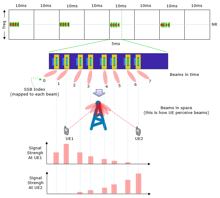
Let me make my own story out of this illustratioin (I hope you already had your version of stories). This is the mechanism by which UE measure and identifies the best beam for a UE.
i) Multiple SSBs are being transmitted with a certain interval.
ii) Each SSB can be identified by a unique number called SSB index
iii) Each SSB is transmitted via a specific beam radiated in a certain direction
iv) Multiple UEs are located at various places around a gNB.
v) UE measures the signal strength of each SSB it detected for a certain period (a period of one SSB Set).
vi) From the measurement result, UE can identifies the SSB index with the strongest signal strength. This SSB with the strongest signal strength is the best beam for the UE 1. (For example, Beam #1 is the best beam(the selected beam for UE1 and Beam#7 is the best beam for the UE 2)
RRC Parameters Related to SS/PBCH Block
The details of SS/PBCH block is informed to UE via various RRC parameters as listed below. It will take pretty much time and effort to fully understand the correlation between the low layer parameters listed above and RRC parameters listed below.
38.331 v19.3.0 (Release 19)
Following is based on
MIB ::=                             SEQUENCE {
    systemFrameNumber                   BIT STRING (SIZE (6)),
    subCarrierSpacingCommon             ENUMERATED {scs15or60, scs30or120},
    ssb-SubcarrierOffset                INTEGER (0..15),
    dmrs-TypeA-Position                 ENUMERATED {pos2, pos3},
    pdcch-ConfigSIB1                    PDCCH-ConfigSIB1,
    cellBarred                          ENUMERATED {barred, notBarred},
    intraFreqReselection                ENUMERATED {allowed, notAllowed},
    spare                               BIT STRING (SIZE (1))
}
Following is based on
SIB1 ::=        SEQUENCE {
    cellSelectionInfo                   SEQUENCE {
        q-RxLevMin                          Q-RxLevMin,
        q-RxLevMinOffset                    INTEGER (1..8)                                              OPTIONAL,   -- Need S
        q-RxLevMinSUL                       Q-RxLevMin                                                  OPTIONAL,   -- Need R
        q-QualMin                           Q-QualMin                                                   OPTIONAL,   -- Need S
        q-QualMinOffset                     INTEGER (1..8)                                              OPTIONAL    -- Need S
    }                                                                                                   OPTIONAL,   -- Cond Standalone
    cellAccessRelatedInfo               CellAccessRelatedInfo,
    connEstFailureControl               ConnEstFailureControl                                           OPTIONAL,   -- Need R
    si-SchedulingInfo                   SI-SchedulingInfo                                               OPTIONAL,   -- Need R
    servingCellConfigCommon             ServingCellConfigCommonSIB                                      OPTIONAL,   -- Need R
    ims-EmergencySupport                ENUMERATED {true}                                               OPTIONAL,   -- Need R
    eCallOverIMS-Support                ENUMERATED {true}                                               OPTIONAL,   -- Need R
    ue-TimersAndConstants               UE-TimersAndConstants                                           OPTIONAL,   -- Need R
    uac-BarringInfo                     SEQUENCE {
        uac-BarringForCommon                UAC-BarringPerCatList                                       OPTIONAL,   -- Need S
        uac-BarringPerPLMN-List             UAC-BarringPerPLMN-List                                     OPTIONAL,   -- Need S
        uac-BarringInfoSetList              UAC-BarringInfoSetList,
        uac-AccessCategory1-SelectionAssistanceInfo CHOICE {
            plmnCommon                          UAC-AccessCategory1-SelectionAssistanceInfo,
            individualPLMNList                  SEQUENCE (SIZE (2..maxPLMN)) OF UAC-AccessCategory1-SelectionAssistanceInfo
        }                                                                                               OPTIONAL    -- Need S
    }                                                                                                   OPTIONAL,   -- Need R
    useFullResumeID                     ENUMERATED {true}                                               OPTIONAL,   -- Need R
    lateNonCriticalExtension            OCTET STRING                                                    OPTIONAL,
    nonCriticalExtension                SIB1-v1610-IEs                                                  OPTIONAL
}
Following is based on
UAC-AccessCategory1-SelectionAssistanceInfo ::= ENUMERATED {a, b, c}
Following is based on
ServingCellConfigCommonSIB ::=      SEQUENCE {
    downlinkConfigCommon                DownlinkConfigCommonSIB,
    uplinkConfigCommon                  UplinkConfigCommonSIB                                       OPTIONAL, -- Need R
    supplementaryUplink                 UplinkConfigCommonSIB                                       OPTIONAL, -- Need R
    n-TimingAdvanceOffset               ENUMERATED { n0, n25600, n39936 }                           OPTIONAL, -- Need S
    ssb-PositionsInBurst                SEQUENCE {
        inOneGroup                          BIT STRING (SIZE (8)),
        groupPresence                       BIT STRING (SIZE (8))                                   OPTIONAL  -- Cond FR2-Only
    },
    ssb-PeriodicityServingCell          ENUMERATED {ms5, ms10, ms20, ms40, ms80, ms160},
    tdd-UL-DL-ConfigurationCommon       TDD-UL-DL-ConfigCommon                                      OPTIONAL, -- Cond TDD
    ss-PBCH-BlockPower                  INTEGER (-60..50),
    ...
    -- the r16 and r17 extension groups are not SSB position related and are not repeated here
}
Following is based on
ServingCellConfigCommon ::=         SEQUENCE {
    physCellId                          PhysCellId                                                          OPTIONAL,   -- Cond HOAndServCellAdd,
    downlinkConfigCommon                DownlinkConfigCommon                                                OPTIONAL,   -- Cond HOAndServCellAdd
    uplinkConfigCommon                  UplinkConfigCommon                                                  OPTIONAL,   -- Need M
    supplementaryUplinkConfig           UplinkConfigCommon                                                  OPTIONAL,   -- Need S
    n-TimingAdvanceOffset               ENUMERATED { n0, n25600, n39936 }                                   OPTIONAL,   -- Need S
    ssb-PositionsInBurst                CHOICE {
        shortBitmap                         BIT STRING (SIZE (4)),
        mediumBitmap                        BIT STRING (SIZE (8)),
        longBitmap                          BIT STRING (SIZE (64))
    }                                                                                                       OPTIONAL, -- Cond AbsFreqSSB
    ssb-periodicityServingCell          ENUMERATED { ms5, ms10, ms20, ms40, ms80, ms160, spare2, spare1 }   OPTIONAL, -- Need S
    dmrs-TypeA-Position                 ENUMERATED {pos2, pos3},
    lte-CRS-ToMatchAround               SetupRelease { RateMatchPatternLTE-CRS }                            OPTIONAL, -- Need M
    rateMatchPatternToAddModList        SEQUENCE (SIZE (1..maxNrofRateMatchPatterns)) OF RateMatchPattern   OPTIONAL, -- Need N
    rateMatchPatternToReleaseList       SEQUENCE (SIZE (1..maxNrofRateMatchPatterns)) OF RateMatchPatternId OPTIONAL, -- Need N
    ssbSubcarrierSpacing                SubcarrierSpacing                                                   OPTIONAL, -- Cond HOAndServCellWithSSB
    tdd-UL-DL-ConfigurationCommon       TDD-UL-DL-ConfigCommon                                              OPTIONAL, -- Cond TDD
    ss-PBCH-BlockPower                  INTEGER (-60..50),
    ...
    -- the r16, r17 and later extension groups are not SSB position related and are not repeated here
}
- When f <= 3Ghz, only the 4 leftmost bits are valid; the UE ignores the 4 rightmost bits.
- When 3 Ghz < f <= 6Ghz, all 8 bits are valid. The first/ leftmost bit corresponds to SS/PBCH block index 0, the second bit corresponds to SS/PBCH block index 1, and so on.
- When 6 Ghz < f, all 8 bit are valid; The first/ leftmost bit corresponds to the first SS/PBCH block index in the group (i.e., to SSB index 0, 8, and so one); the second bit corresponds to the second SS/PBCH block index in the group (i.e., to SSB index 1, 9, and so one), and so on. Value 0 in the bitmap indicates that the corresponding SS/PBCH block is not transmitted while value 1 indicates that the corresponding SS/PBCH block is transmitted.
Following is based on
FrequencyInfoDL ::=                 SEQUENCE {
    absoluteFrequencySSB                ARFCN-ValueNR                                                   OPTIONAL,   -- Cond SpCellAdd
    frequencyBandList                   MultiFrequencyBandListNR,
    absoluteFrequencyPointA             ARFCN-ValueNR,
    scs-SpecificCarrierList             SEQUENCE (SIZE (1..maxSCSs)) OF SCS-SpecificCarrier,
    ...,
    [[
    referenceCell-r18                   ServCellIndex                                                   OPTIONAL    -- Cond SSBlessSCell
    ]]
}
Following is based on
SCS-SpecificCarrier ::=             SEQUENCE {
    offsetToCarrier                     INTEGER (0..2199),
    subcarrierSpacing                   SubcarrierSpacing,
    carrierBandwidth                    INTEGER (1..maxNrofPhysicalResourceBlocks),
    ...,
    [[
    txDirectCurrentLocation         INTEGER (0..4095)                                       OPTIONAL            -- Need S
    ]],
    [[
    sbfd-Subband-Allocation-r19     SBFD-Subband-Allocation-r19                             OPTIONAL            -- Need R
    ]]
}
Reference : YouTube
[1] 5G Explained: Synchronization Signal Blocks in 5G NR
|
|
|