NR has no always-on cell reference signal, so every PDSCH has to carry the reference symbols the UE needs to estimate the channel it just arrived on. That single decision is where most of the complexity on this page comes from. The summary below is the short version, and the sections after it work through how the symbols are placed, generated and mapped.
|
PDSCH DMRS(DeModulation Reference Signal) in Detail
The page is arranged from the outside in. The basic questions settle the vocabulary. The parameters then map each RRC field onto the physical layer name it sets, and the examples show what a given configuration puts on the grid. Sequence generation and resource element mapping come last because they are the mechanism behind everything above them, and the tables they depend on are collected at the end.
PDSCH DMRS is a special type of physical layer signal which functions as a reference signal for decoding PDSCH. In LTE (at least in TM1, 2, 3, 4), we don't need this kind of special DMRS for PDSCH because we can use CRS(Cell Specific Reference Signal) for PDSCH decoding. However, in 5G/NR there is no CRS. That's why we need the DMRS dedicated for PDSCH decoding.
- Basic Questions
- Parameters
- Examples
- Layers and Number of DMRS CDM Group(s) Without Data
- dmrs-type
- dmrs-AdditionalPosition
- dmrs-TypeA-Position
- maxLength
- PDSCH Mapping Type B
- Sequence Generation
- Resource Element Mapping
- Tables
- Table 7.4.1.1.2-1: Parameters for PDSCH DM-RS configuration type 1
- Table 7.4.1.1.2-2: Parameters for PDSCH DM-RS configuration type 2
- Table 7.4.1.1.2-3: PDSCH DM-RS positions l bar for single-symbol DM-RS
- Table 7.4.1.1.2-4: PDSCH DM-RS positions l bar for double-symbol DM-RS
- Table 7.4.1.1.2-5: PDSCH DM-RS time index l' and antenna ports p
- Reference
- Get the Test Procedure and Log / Amarisoft TechAcademy
Basic questions.
DMRS configuration sometimes is pretty confusing unless you have some type of big picture. If you frequently refresh yourself with the following questions, it will be helpful when you read further details in this page.
What is the difference between Mapping Type A and B in terms of resource allocation ?
Type A can start only at symbol 2 or 3 within a slot, meaning that SLIV that start from symbol 4 or higher cannot use this type of DMRS.
Type B starts always at the first symbols of scheduled SLIV.
What is the difference between configuration type 1 and 2 in terms of resource allocation ?
In Configuration type 1, the minimum resource element group in frequency domain is one RE. In Configuration type 2, the minimum resource element group in frequency domain is two consecutive REs. See the pictures in Resource Element Mapping.
What is the effect of port number on DMRS resource element position ?
Each layer needs its own reference signal, and the ports have to stay separable at the receiver. Two mechanisms do that together: the ports sit on different subcarrier combs, and ports sharing a comb are separated by a code instead. As antenna port number changes, the location of DMRS position in frequency domain changes. Check out this note for the details.
How many DMRS symbol can be put into a slot ?
Minimum number is 1, but it can be more than 1 depending on dmrs-AdditionalPosition in RRC. Max number is 4. See 38.211 - Table 7.4.1.1.2-3 and 38.211 - Table 7.4.1.1.2-4 for the details.
Parameters
DMRS is configured from more than one place, and the table below is the map between them. The physical layer parameter in 38.211 sits in the left column, and the higher layer parameter that sets it sits beside it. Reading it in that direction answers the question a log usually raises, which is which RRC field produced the pattern on the grid.
|
38.211-7.4.1.1 |
Higher Layer Parameter |
Value |
Comment |
|
|
DL-DMRS-Scrambling-ID |
{0,1} |
Sequence Generation |
|
|
DL-DMRS-Scrambling-ID |
{0,1,..,65535} |
Sequence Generation |
|
Configuration Type |
DL-DMRS-config-type dmrs-Type |
type1, type2 |
RE Mapping |
|
|
DL-DMRS-typeA-pos dmrs-TypeA-Position |
pos2, pos3 |
RE Mapping |
|
|
DL-DMRS-add-pos dmrs-AdditionalPosition |
pos0, pos1, pos2, pos3 |
RE Mapping |
|
|
DL-DMRS-max-len |
|
RE Mapping |
|
single or double symbol |
|
|
RE Mapping |


Following is based on
MIB ::= SEQUENCE {
    ...
    dmrs-TypeA-Position                 ENUMERATED {pos2, pos3},
    ...
}

PDSCH-TimeDomainResourceAllocation ::=   SEQUENCE {
    k0                                      INTEGER(0..32)                          OPTIONAL,   -- Need S
    mappingType                             ENUMERATED {typeA, typeB},
    startSymbolAndLength                    INTEGER (0..127)
}

PDSCH-TimeDomainResourceAllocation-r16 ::= SEQUENCE {
    k0-r16                                  INTEGER(0..32)                          OPTIONAL,   -- Need S
    mappingType-r16                         ENUMERATED {typeA, typeB},
    startSymbolAndLength-r16                INTEGER (0..127),
    repetitionNumber-r16                    ENUMERATED {n2, n3, n4, n5, n6, n7, n8, n16}
                                                                                    OPTIONAL,   -- Cond Formats1-0and1-1
    ...,
    [[
    k0-v1710                                INTEGER(33..128)                        OPTIONAL    -- Need S
    ]]
}
Following is based on
PDSCH-Config ::=                        SEQUENCE {
    ...
    dmrs-DownlinkForPDSCH-MappingTypeA      SetupRelease { DMRS-DownlinkConfig }   OPTIONAL,   -- Need M
    dmrs-DownlinkForPDSCH-MappingTypeB      SetupRelease { DMRS-DownlinkConfig }   OPTIONAL,   -- Need M
    ...
}

DMRS-DownlinkConfig ::=             SEQUENCE {
    dmrs-Type                           ENUMERATED {type2}                          OPTIONAL,   -- Need S
    dmrs-AdditionalPosition             ENUMERATED {pos0, pos1, pos3}               OPTIONAL,   -- Need S
    maxLength                           ENUMERATED {len2}                           OPTIONAL,   -- Need S
    scramblingID0                       INTEGER (0..65535)                          OPTIONAL,   -- Need S
    scramblingID1                       INTEGER (0..65535)                          OPTIONAL,   -- Need S
    phaseTrackingRS                     SetupRelease { PTRS-DownlinkConfig }   OPTIONAL,   -- Need M
    ...,
    [[
    dmrs-Downlink-r16                   ENUMERATED {enabled}                        OPTIONAL    -- Need R
    ]],
    [[
    dmrs-TypeEnh-r18                    ENUMERATED {enabled}                        OPTIONAL    -- Need R
    ]]
}

PTRS-DownlinkConfig ::=             SEQUENCE {
    frequencyDensity                    SEQUENCE (SIZE (2)) OF INTEGER (1..276)     OPTIONAL,   -- Need S
    timeDensity                         SEQUENCE (SIZE (3)) OF INTEGER (0..29)      OPTIONAL,   -- Need S
    epre-Ratio                          INTEGER (0..3)                              OPTIONAL,   -- Need S
    resourceElementOffset               ENUMERATED { offset01, offset10, offset11 } OPTIONAL,   -- Need S
    ...,
    [[
    maxNrofPorts-r16                    ENUMERATED {n1, n2}                         OPTIONAL    -- Need R
    ]]
}
It would be almost impossible for you to get the practical meaning of these parameters just by looking into the specification unless you are the person who designed this algorithm or create your own program to implement this specification and plot it in graphics. I am not the person who desgined the algorithm and I don't have my own program to implement it. So it was so difficult for me to get any intuitive understandings on these parameters and algorithm. Fortunately, I got a chance to try with Matlab 5G library. Followings are the examples in graphics that I created using Matlab 5G library. I posted Matlab code and more examples here. The subcarrier spacing used in this example is 30 Khz and for the simplicity I assigned only one RB for the PDSCH.
Examples
Look through these examples and try to get some intuitive pattern. If it is not easy for you to see any pattern, refer to Resource Element Mapping section first and then get back to these examples.
For the valid configurations as of current 3gpp specification, refer to following notes
Following is the Matlab 5G Toolbox code that I wrote for all the examples in this page
|
carrier = nrCarrierConfig('NSlot',0);
pdsch = nrPDSCHConfig; pdsch.NumLayers = 1; pdsch.PRBSet = 0:50; pdsch.MappingType = 'A'; pdsch.SymbolAllocation = [0 14]; % [startSymbol Length]
dmrs = nrPDSCHDMRSConfig; dmrs.DMRSConfigurationType = 1; dmrs.DMRSLength = 1; dmrs.DMRSAdditionalPosition = 0; dmrs.DMRSTypeAPosition = 2;
if pdsch.NumLayers == 1 dmrs.DMRSPortSet = [0]; elseif pdsch.NumLayers == 2 dmrs.DMRSPortSet = [0 1]; elseif pdsch.NumLayers == 3 dmrs.DMRSPortSet = [0 1 2]; elseif pdsch.NumLayers == 4 dmrs.DMRSPortSet = [0 1 2 3]; end
dmrs.NumCDMGroupsWithoutData = 1; dmrs.NIDNSCID = 10; dmrs.NSCID = 0;
pdsch.DMRS = dmrs;
sym_dmrs = nrPDSCHDMRS(carrier,pdsch,'OutputDataType','single'); ind_dmrs = nrPDSCHDMRSIndices(carrier,pdsch,'IndexBase','0based','IndexOrientation','carrier'); ind_pdsch = nrPDSCHIndices(carrier,pdsch,'IndexBase','0based','IndexOrientation','carrier');
grid = complex(zeros([carrier.NSizeGrid*12 carrier.SymbolsPerSlot pdsch.NumLayers])); grid(ind_dmrs+1) = sym_dmrs; grid(ind_pdsch+1) = 0.5;
% Plot the grid hFig = figure(2); set(hFig, 'Position', [100 100 900 200]); set(gcf,'color','w');
for i = 1:pdsch.NumLayers subplot(1,4,i) hold on; imagesc(abs(grid(:,:,i))); title(strcat('Port 100',num2str(dmrs.DMRSPortSet(i)))); for i = 2:14 line([i-0.5 i-0.5],[0 273*12],'Color','white'); end for j = 1:12 line([0 15],[j+0.5 j+0.5],'Color','white'); end hold off; axis xy; box on; xlabel('OFDM Symbols'); ylabel('Subcarriers'); xlim([0.5 14.5]); ylim([0.5 12.5]); set(gca,'xtick',[0:14]); set(gca,'xticklabel',{'','0','1','2','3','4','5','6','7','8','9','10','11','12','13'}); set(gca,'ytick',[0:12]); set(gca,'yticklabel',{'','0','1','2','3','4','5','6','7','8','9','10','11'}); end |
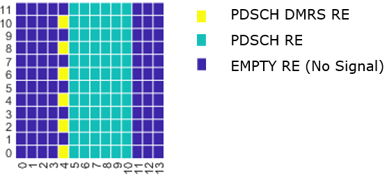
NOTE : Following is the color coding for the RE (Resource Elements) in the examples in this note
< Layers and Number of DMRS CDM Group(s) Without Data >
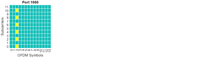
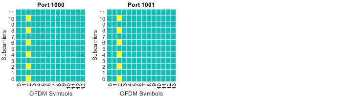
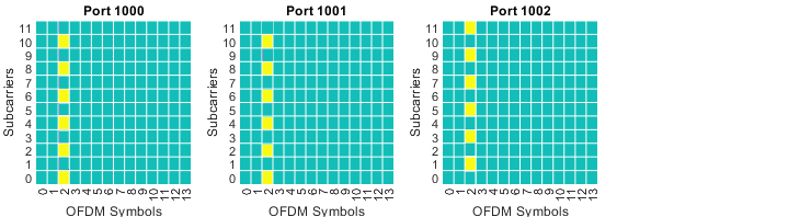
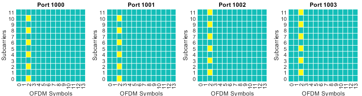
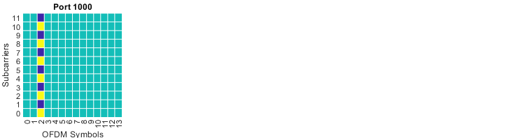
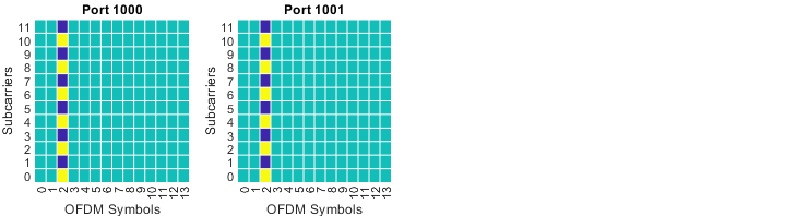
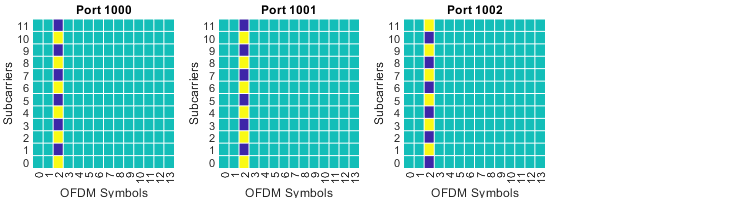
The number of layers decides how many ports carry DMRS, and the CDM group count decides how much of the grid is kept clear of data around them. The configurations below vary both, and the plots show one resource grid per port so the two effects can be told apart.
|
pdsch.NumLayers = 1; pdsch.MappingType = 'A'; pdsch.SymbolAllocation = [0 14]; % [startSymbol Length] dmrs.DMRSConfigurationType = 1; dmrs.DMRSLength = 1; dmrs.DMRSAdditionalPosition = 0; dmrs.DMRSTypeAPosition = 2; dmrs.NumCDMGroupsWithoutData = 1; dmrs.NIDNSCID = 10; dmrs.NSCID = 0; |
|
|
|
pdsch.NumLayers = 2; pdsch.MappingType = 'A'; pdsch.SymbolAllocation = [0 14]; % [startSymbol Length] dmrs.DMRSConfigurationType = 1; dmrs.DMRSLength = 1; dmrs.DMRSAdditionalPosition = 0; dmrs.DMRSTypeAPosition = 2; dmrs.NumCDMGroupsWithoutData = 1; dmrs.NIDNSCID = 10; dmrs.NSCID = 0; |
|
|
|
pdsch.NumLayers = 3; pdsch.MappingType = 'A'; pdsch.SymbolAllocation = [0 14]; % [startSymbol Length] dmrs.DMRSConfigurationType = 1; dmrs.DMRSLength = 1; dmrs.DMRSAdditionalPosition = 0; dmrs.DMRSTypeAPosition = 2; dmrs.NumCDMGroupsWithoutData = 1; dmrs.NIDNSCID = 10; dmrs.NSCID = 0; |
|
|
|
pdsch.NumLayers = 4; pdsch.MappingType = 'A'; pdsch.SymbolAllocation = [0 14]; % [startSymbol Length] dmrs.DMRSConfigurationType = 1; dmrs.DMRSLength = 1; dmrs.DMRSAdditionalPosition = 0; dmrs.DMRSTypeAPosition = 2; dmrs.NumCDMGroupsWithoutData = 1; dmrs.NIDNSCID = 10; dmrs.NSCID = 0; |
|
|
|
pdsch.NumLayers = 1; pdsch.MappingType = 'A'; pdsch.SymbolAllocation = [0 14]; % [startSymbol Length] dmrs.DMRSConfigurationType = 1; dmrs.DMRSLength = 1; dmrs.DMRSAdditionalPosition = 0; dmrs.DMRSTypeAPosition = 2; dmrs.NumCDMGroupsWithoutData = 2; dmrs.NIDNSCID = 10; dmrs.NSCID = 0; |
|
|
|
pdsch.NumLayers = 2; pdsch.MappingType = 'A'; pdsch.SymbolAllocation = [0 14]; % [startSymbol Length] dmrs.DMRSConfigurationType = 1; dmrs.DMRSLength = 1; dmrs.DMRSAdditionalPosition = 0; dmrs.DMRSTypeAPosition = 2; dmrs.NumCDMGroupsWithoutData = 2; dmrs.NIDNSCID = 10; dmrs.NSCID = 0; |
|
|
|
pdsch.NumLayers = 3; pdsch.MappingType = 'A'; pdsch.SymbolAllocation = [0 14]; % [startSymbol Length] dmrs.DMRSConfigurationType = 1; dmrs.DMRSLength = 1; dmrs.DMRSAdditionalPosition = 0; dmrs.DMRSTypeAPosition = 2; dmrs.NumCDMGroupsWithoutData = 2; dmrs.NIDNSCID = 10; dmrs.NSCID = 0; |
|
|
|
pdsch.NumLayers = 4; pdsch.MappingType = 'A'; pdsch.SymbolAllocation = [0 14]; % [startSymbol Length] dmrs.DMRSConfigurationType = 1; dmrs.DMRSLength = 1; dmrs.DMRSAdditionalPosition = 0; dmrs.DMRSTypeAPosition = 2; dmrs.NumCDMGroupsWithoutData = 2; dmrs.NIDNSCID = 10; dmrs.NSCID = 0; |
|
|
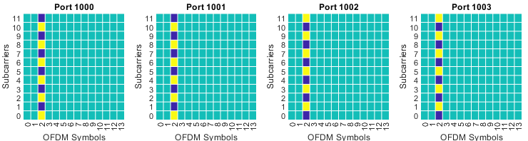
|
pdsch.NumLayers = 1; pdsch.MappingType = 'A'; pdsch.SymbolAllocation = [0 14]; % [startSymbol Length] dmrs.DMRSConfigurationType = 2; dmrs.DMRSLength = 1; dmrs.DMRSAdditionalPosition = 0; dmrs.DMRSTypeAPosition = 2; dmrs.NumCDMGroupsWithoutData = 1; dmrs.NIDNSCID = 10; dmrs.NSCID = 0; |
|
|

|
pdsch.NumLayers = 1; pdsch.MappingType = 'A'; pdsch.SymbolAllocation = [0 14]; % [startSymbol Length] dmrs.DMRSConfigurationType = 2; dmrs.DMRSLength = 1; dmrs.DMRSAdditionalPosition = 0; dmrs.DMRSTypeAPosition = 2; dmrs.NumCDMGroupsWithoutData = 2; dmrs.NIDNSCID = 10; dmrs.NSCID = 0; |
|
|

|
pdsch.NumLayers = 1; pdsch.MappingType = 'A'; pdsch.SymbolAllocation = [0 14]; % [startSymbol Length] dmrs.DMRSConfigurationType = 2; dmrs.DMRSLength = 1; dmrs.DMRSAdditionalPosition = 0; dmrs.DMRSTypeAPosition = 2; dmrs.NumCDMGroupsWithoutData = 3; dmrs.NIDNSCID = 10; dmrs.NSCID = 0; |
|
|

|
pdsch.NumLayers = 2; pdsch.MappingType = 'A'; pdsch.SymbolAllocation = [0 14]; % [startSymbol Length] dmrs.DMRSConfigurationType = 2; dmrs.DMRSLength = 1; dmrs.DMRSAdditionalPosition = 0; dmrs.DMRSTypeAPosition = 2; dmrs.NumCDMGroupsWithoutData = 1; dmrs.NIDNSCID = 10; dmrs.NSCID = 0; |
|
|

|
pdsch.NumLayers = 2; pdsch.MappingType = 'A'; pdsch.SymbolAllocation = [0 14]; % [startSymbol Length] dmrs.DMRSConfigurationType = 2; dmrs.DMRSLength = 1; dmrs.DMRSAdditionalPosition = 0; dmrs.DMRSTypeAPosition = 2; dmrs.NumCDMGroupsWithoutData = 2; dmrs.NIDNSCID = 10; dmrs.NSCID = 0; |
|
|

|
pdsch.NumLayers = 2; pdsch.MappingType = 'A'; pdsch.SymbolAllocation = [0 14]; % [startSymbol Length] dmrs.DMRSConfigurationType = 2; dmrs.DMRSLength = 1; dmrs.DMRSAdditionalPosition = 0; dmrs.DMRSTypeAPosition = 2; dmrs.NumCDMGroupsWithoutData = 3; dmrs.NIDNSCID = 10; dmrs.NSCID = 0; |
|
|

|
pdsch.NumLayers = 3; pdsch.MappingType = 'A'; pdsch.SymbolAllocation = [0 14]; % [startSymbol Length] dmrs.DMRSConfigurationType = 2; dmrs.DMRSLength = 1; dmrs.DMRSAdditionalPosition = 0; dmrs.DMRSTypeAPosition = 2; dmrs.NumCDMGroupsWithoutData = 1; dmrs.NIDNSCID = 10; dmrs.NSCID = 0; |
|
|

|
pdsch.NumLayers = 3; pdsch.MappingType = 'A'; pdsch.SymbolAllocation = [0 14]; % [startSymbol Length] dmrs.DMRSConfigurationType = 2; dmrs.DMRSLength = 1; dmrs.DMRSAdditionalPosition = 0; dmrs.DMRSTypeAPosition = 2; dmrs.NumCDMGroupsWithoutData = 2; dmrs.NIDNSCID = 10; dmrs.NSCID = 0; |
|
|

|
pdsch.NumLayers = 3; pdsch.MappingType = 'A'; pdsch.SymbolAllocation = [0 14]; % [startSymbol Length] dmrs.DMRSConfigurationType = 2; dmrs.DMRSLength = 1; dmrs.DMRSAdditionalPosition = 0; dmrs.DMRSTypeAPosition = 2; dmrs.NumCDMGroupsWithoutData = 3; dmrs.NIDNSCID = 10; dmrs.NSCID = 0; |
|
|

|
pdsch.NumLayers = 4; pdsch.MappingType = 'A'; pdsch.SymbolAllocation = [0 14]; % [startSymbol Length] dmrs.DMRSConfigurationType = 2; dmrs.DMRSLength = 1; dmrs.DMRSAdditionalPosition = 0; dmrs.DMRSTypeAPosition = 2; dmrs.NumCDMGroupsWithoutData = 1; dmrs.NIDNSCID = 10; dmrs.NSCID = 0; |
|
|

|
pdsch.NumLayers = 4; pdsch.MappingType = 'A'; pdsch.SymbolAllocation = [0 14]; % [startSymbol Length] dmrs.DMRSConfigurationType = 2; dmrs.DMRSLength = 1; dmrs.DMRSAdditionalPosition = 0; dmrs.DMRSTypeAPosition = 2; dmrs.NumCDMGroupsWithoutData = 2; dmrs.NIDNSCID = 10; dmrs.NSCID = 0; |
|
|

|
pdsch.NumLayers = 4; pdsch.MappingType = 'A'; pdsch.SymbolAllocation = [0 14]; % [startSymbol Length] dmrs.DMRSConfigurationType = 2; dmrs.DMRSLength = 1; dmrs.DMRSAdditionalPosition = 0; dmrs.DMRSTypeAPosition = 2; dmrs.NumCDMGroupsWithoutData = 3; dmrs.NIDNSCID = 10; dmrs.NSCID = 0; |
|
|

< dmrs-type >
Type 1 and type 2 differ in how the subcarriers are divided between ports. Type 1 uses every other subcarrier, and type 2 uses pairs with a wider spacing. Type 2 therefore supports more ports, at the cost of sampling the channel more coarsely in frequency.
|
pdsch.NumLayers = 2; pdsch.MappingType = 'A'; pdsch.SymbolAllocation = [0 14]; % [startSymbol Length] dmrs.DMRSConfigurationType = 1; dmrs.DMRSLength = 1; dmrs.DMRSAdditionalPosition = 0; dmrs.DMRSTypeAPosition = 2; dmrs.NumCDMGroupsWithoutData = 1; dmrs.NIDNSCID = 10; dmrs.NSCID = 0; |
|
|

|
pdsch.NumLayers = 2; pdsch.MappingType = 'A'; pdsch.SymbolAllocation = [0 14]; % [startSymbol Length] dmrs.DMRSConfigurationType = 2; dmrs.DMRSLength = 1; dmrs.DMRSAdditionalPosition = 0; dmrs.DMRSTypeAPosition = 2; dmrs.NumCDMGroupsWithoutData = 1; dmrs.NIDNSCID = 10; dmrs.NSCID = 0; |
|
|

|
pdsch.NumLayers = 2; pdsch.MappingType = 'A'; pdsch.SymbolAllocation = [0 14]; % [startSymbol Length] dmrs.DMRSConfigurationType = 1; dmrs.DMRSLength = 1; dmrs.DMRSAdditionalPosition = 0; dmrs.DMRSTypeAPosition = 2; dmrs.NumCDMGroupsWithoutData = 2; dmrs.NIDNSCID = 10; dmrs.NSCID = 0; |
|
|

|
pdsch.NumLayers = 4; pdsch.MappingType = 'A'; pdsch.SymbolAllocation = [0 14]; % [startSymbol Length] dmrs.DMRSConfigurationType = 1; dmrs.DMRSLength = 1; dmrs.DMRSAdditionalPosition = 0; dmrs.DMRSTypeAPosition = 2; dmrs.NumCDMGroupsWithoutData = 2; dmrs.NIDNSCID = 10; dmrs.NSCID = 0; |
|
|

|
pdsch.NumLayers = 4; pdsch.MappingType = 'A'; pdsch.SymbolAllocation = [0 14]; % [startSymbol Length] dmrs.DMRSConfigurationType = 1; dmrs.DMRSLength = 1; dmrs.DMRSAdditionalPosition = 0; dmrs.DMRSTypeAPosition = 2; dmrs.NumCDMGroupsWithoutData = 1; dmrs.NIDNSCID = 10; dmrs.NSCID = 0; |
|
|

|
pdsch.NumLayers = 4; pdsch.MappingType = 'A'; pdsch.SymbolAllocation = [0 14]; % [startSymbol Length] dmrs.DMRSConfigurationType = 2; dmrs.DMRSLength = 1; dmrs.DMRSAdditionalPosition = 0; dmrs.DMRSTypeAPosition = 2; dmrs.NumCDMGroupsWithoutData = 1; dmrs.NIDNSCID = 10; dmrs.NSCID = 0; |
|
|

|
pdsch.NumLayers = 4; pdsch.MappingType = 'A'; pdsch.SymbolAllocation = [0 14]; % [startSymbol Length] dmrs.DMRSConfigurationType = 1; dmrs.DMRSLength = 1; dmrs.DMRSAdditionalPosition = 0; dmrs.DMRSTypeAPosition = 2; dmrs.NumCDMGroupsWithoutData = 2; dmrs.NIDNSCID = 10; dmrs.NSCID = 0; |
|
|

|
pdsch.NumLayers = 4; pdsch.MappingType = 'A'; pdsch.SymbolAllocation = [0 14]; % [startSymbol Length] dmrs.DMRSConfigurationType = 2; dmrs.DMRSLength = 1; dmrs.DMRSAdditionalPosition = 0; dmrs.DMRSTypeAPosition = 2; dmrs.NumCDMGroupsWithoutData = 2; dmrs.NIDNSCID = 10; dmrs.NSCID = 0; |
|
|

< dmrs-AdditionalPosition >
One DMRS symbol is enough to estimate a channel that does not change across the slot. It is not enough when the UE is moving, because the estimate ages. The configurations below add DMRS symbols later in the slot, and the cost is the resource elements they take from data.
|
pdsch.NumLayers = 4; pdsch.MappingType = 'A'; pdsch.SymbolAllocation = [0 14]; % [startSymbol Length] dmrs.DMRSConfigurationType = 1; dmrs.DMRSLength = 1; dmrs.DMRSAdditionalPosition = 0; dmrs.DMRSTypeAPosition = 2; dmrs.NumCDMGroupsWithoutData = 2; dmrs.NIDNSCID = 10; dmrs.NSCID = 0; |
|
|

|
pdsch.NumLayers = 4; pdsch.MappingType = 'A'; pdsch.SymbolAllocation = [0 14]; % [startSymbol Length] dmrs.DMRSConfigurationType = 1; dmrs.DMRSLength = 1; dmrs.DMRSAdditionalPosition = 1; dmrs.DMRSTypeAPosition = 2; dmrs.NumCDMGroupsWithoutData = 2; dmrs.NIDNSCID = 10; dmrs.NSCID = 0; |
|
|

|
pdsch.NumLayers = 4; pdsch.MappingType = 'A'; pdsch.SymbolAllocation = [0 14]; % [startSymbol Length] dmrs.DMRSConfigurationType = 1; dmrs.DMRSLength = 1; dmrs.DMRSAdditionalPosition = 2; dmrs.DMRSTypeAPosition = 2; dmrs.NumCDMGroupsWithoutData = 2; dmrs.NIDNSCID = 10; dmrs.NSCID = 0; |
|
|

|
pdsch.NumLayers = 4; pdsch.MappingType = 'A'; pdsch.SymbolAllocation = [0 14]; % [startSymbol Length] dmrs.DMRSConfigurationType = 1; dmrs.DMRSLength = 1; dmrs.DMRSAdditionalPosition = 3; dmrs.DMRSTypeAPosition = 2; dmrs.NumCDMGroupsWithoutData = 2; dmrs.NIDNSCID = 10; dmrs.NSCID = 0; |
|
|

< dmrs-TypeA-Position >
For mapping type A the first DMRS symbol is counted from the start of the slot rather than the start of the allocation. It is either symbol 2 or symbol 3. The value comes from the MIB, so it is fixed before the UE has any dedicated configuration.
|
pdsch.NumLayers = 4; pdsch.MappingType = 'A'; pdsch.SymbolAllocation = [0 14]; % [startSymbol Length] dmrs.DMRSConfigurationType = 1; dmrs.DMRSLength = 1; dmrs.DMRSAdditionalPosition = 0; dmrs.DMRSTypeAPosition = 2; dmrs.NumCDMGroupsWithoutData = 2; dmrs.NIDNSCID = 10; dmrs.NSCID = 0; |
|
|

|
pdsch.NumLayers = 4; pdsch.MappingType = 'A'; pdsch.SymbolAllocation = [0 14]; % [startSymbol Length] dmrs.DMRSConfigurationType = 1; dmrs.DMRSLength = 1; dmrs.DMRSAdditionalPosition = 0; dmrs.DMRSTypeAPosition = 3; dmrs.NumCDMGroupsWithoutData = 2; dmrs.NIDNSCID = 10; dmrs.NSCID = 0; |
|
|

|
pdsch.NumLayers = 4; pdsch.MappingType = 'A'; pdsch.SymbolAllocation = [0 14]; % [startSymbol Length] dmrs.DMRSConfigurationType = 1; dmrs.DMRSLength = 1; dmrs.DMRSAdditionalPosition = 3; dmrs.DMRSTypeAPosition = 3; dmrs.NumCDMGroupsWithoutData = 2; dmrs.NIDNSCID = 10; dmrs.NSCID = 0; |
|
|

< maxLength >
A single DMRS symbol limits how many ports can be separated. Setting maxLength to len2 lets the front loaded DMRS occupy two adjacent symbols, which doubles the code length available for separating ports. The plots below show the second symbol appearing directly after the first.
|
pdsch.NumLayers = 4; pdsch.MappingType = 'A'; pdsch.SymbolAllocation = [0 14]; % [startSymbol Length] dmrs.DMRSConfigurationType = 1; dmrs.DMRSLength = 2; dmrs.DMRSAdditionalPosition = 0; dmrs.DMRSTypeAPosition = 2; dmrs.NumCDMGroupsWithoutData = 2; dmrs.NIDNSCID = 10; dmrs.NSCID = 0; |
|
|

|
pdsch.NumLayers = 4; pdsch.MappingType = 'A'; pdsch.SymbolAllocation = [0 14]; % [startSymbol Length] dmrs.DMRSConfigurationType = 1; dmrs.DMRSLength = 2; dmrs.DMRSAdditionalPosition = 0; dmrs.DMRSTypeAPosition = 2; dmrs.NumCDMGroupsWithoutData = 2; dmrs.NIDNSCID = 10; dmrs.NSCID = 0; |
|
|

< PDSCH Mapping Type B>
Mapping type B ties the first DMRS symbol to the allocation rather than to the slot. The allocation in these examples starts at symbol 4 and runs for seven symbols, and the DMRS lands on symbol 4 with it. That is what makes type B usable for short allocations that begin part way through a slot.
|
pdsch.NumLayers = 2; pdsch.MappingType = 'B'; pdsch.SymbolAllocation = [4 7]; % [startSymbol Length] dmrs.DMRSConfigurationType = 1; dmrs.DMRSLength = 1; dmrs.DMRSAdditionalPosition = 0; dmrs.DMRSTypeAPosition = 0; dmrs.NumCDMGroupsWithoutData = 1; dmrs.NIDNSCID = 10; dmrs.NSCID = 0; |
|
|

|
pdsch.NumLayers = 2; pdsch.MappingType = 'B'; pdsch.SymbolAllocation = [4 7]; % [startSymbol Length] dmrs.DMRSConfigurationType = 1; dmrs.DMRSLength = 1; dmrs.DMRSAdditionalPosition = 0; dmrs.DMRSTypeAPosition = 0; dmrs.NumCDMGroupsWithoutData = 2; dmrs.NIDNSCID = 10; dmrs.NSCID = 0; |
|
|

|
pdsch.NumLayers = 2; pdsch.MappingType = 'B'; pdsch.SymbolAllocation = [4 7]; % [startSymbol Length] dmrs.DMRSConfigurationType = 1; dmrs.DMRSLength = 1; dmrs.DMRSAdditionalPosition = 1; dmrs.DMRSTypeAPosition = 0; dmrs.NumCDMGroupsWithoutData = 1; dmrs.NIDNSCID = 10; dmrs.NSCID = 0; |
|
|

|
pdsch.NumLayers = 2; pdsch.MappingType = 'B'; pdsch.SymbolAllocation = [4 7]; % [startSymbol Length] dmrs.DMRSConfigurationType = 1; dmrs.DMRSLength = 1; dmrs.DMRSAdditionalPosition = 1; dmrs.DMRSTypeAPosition = 0; dmrs.NumCDMGroupsWithoutData = 2; dmrs.NIDNSCID = 10; dmrs.NSCID = 0; |
|
|

|
pdsch.NumLayers = 4; pdsch.MappingType = 'B'; pdsch.SymbolAllocation = [4 7]; % [startSymbol Length] dmrs.DMRSConfigurationType = 1; dmrs.DMRSLength = 1; dmrs.DMRSAdditionalPosition = 1; dmrs.DMRSTypeAPosition = 0; dmrs.NumCDMGroupsWithoutData = 2; dmrs.NIDNSCID = 10; dmrs.NSCID = 0; |
|
|

|
pdsch.NumLayers = 4; pdsch.MappingType = 'B'; pdsch.SymbolAllocation = [4 7]; % [startSymbol Length] dmrs.DMRSConfigurationType = 1; dmrs.DMRSLength = 1; dmrs.DMRSAdditionalPosition = 0; dmrs.DMRSTypeAPosition = 0; dmrs.NumCDMGroupsWithoutData = 2; dmrs.NIDNSCID = 10; dmrs.NSCID = 0; |
|
|

|
pdsch.NumLayers = 4; pdsch.MappingType = 'B'; pdsch.SymbolAllocation = [4 7]; % [startSymbol Length] dmrs.DMRSConfigurationType = 2; dmrs.DMRSLength = 1; dmrs.DMRSAdditionalPosition = 0; dmrs.DMRSTypeAPosition = 0; dmrs.NumCDMGroupsWithoutData = 2; dmrs.NIDNSCID = 10; dmrs.NSCID = 0; |
|
|

Sequence Generation
Following shows how the DMRS data is generated as the baseband. You don't need to understand every details of this unless you are an engineer working at this specific item. Just try to understand what kind of parameters are involved in this process.
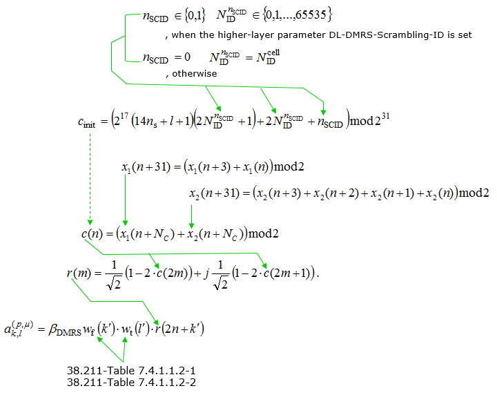
- The sequence generation starts with defining the scrambling identity NIDSCID. This identity can range from 0 to 65535 and is set based on whether a higher-layer parameter DL-DMRS-Scrambling-ID is configured.
- If the DL-DMRS-Scrambling-ID is not set, NIDSCID defaults to the cell ID NIDcell.
- The initialization sequence cinit is then calculated using a formula that incorporates NIDSCID, the slot number ns, and other parameters, modulo 231.
- Two sequences x1(n) and x2(n) are generated and used to create the scrambling sequence c(n) through a specified polynomial relationship and modulo 2 arithmetic.
- The DMRS sequence r(m) is constructed using the scrambling sequence, involving complex number calculations to produce the final sequence.
- Finally, the actual PDSCH DMRS symbols ak',l'(p,u) are obtained by scaling the DMRS sequence with a precoding matrix wk' and a sequence of phase shifts wtilde(r).
Three properties are being bought by this construction, and each stage buys one of them. The Gold sequence gives low cross-correlation, so a UE that hears a neighbouring cell's DMRS sees noise rather than a competing estimate. The dependence of cinit on the slot number and the symbol index means the sequence differs from symbol to symbol, so an interferer never lines up twice in the same way.
The scrambling identity is what separates users rather than cells. Two UEs scheduled on the same resource in MU-MIMO need different sequences. The network gives them different nSCID values or different scrambling IDs, and the DCI says which of scramblingID0 and scramblingID1 applies. Where no scrambling ID is configured at all, the cell ID is used and the separation falls back to being between cells only.
The final expression is where the ports are separated. The sequence r is multiplied by wf(k') and wt(l'), a code across frequency and a code across time, and those two come from the 38.211 tables collected under Tables. Ports sharing a comb differ only in that code, which is why the tables have to be read alongside the equations rather than after them.
Resource Element Mapping
Resource Mapping of PDSCH DMRS is done as following equation. For simplicity, let's think of the location of resource element only (i.e, let's think only of k and l). k represents frequency domain location and l represents time domain location.
With this in mind, the first thing you can notice would be
- Configuration type changes the location pattern in frequency domain
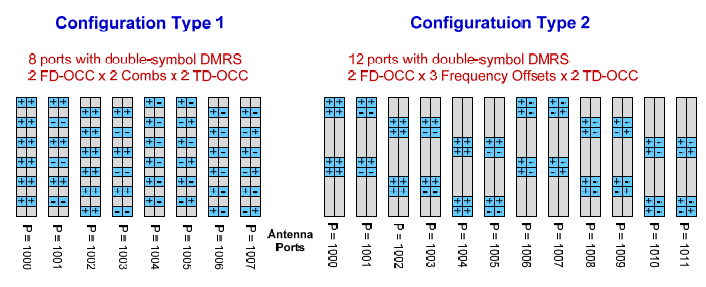
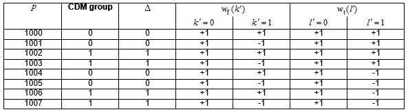
- Configurataion Type 1 : 3 pairs(6 Resource Elements:RE) of DMRS are dispersed in one OFDM symbol/one RB at the interval of 4 REs (4n). The two RE in each pare are apart at the interval of 2 RE(2k'). In short, 6 REs of DMRS symbols are dispersed at every other REs in frequency domain. This supports 8 DMRS ports in case of double-symbol DMRS(port 1000~1007) and 4 DMRS ports in case of single symbol DMRS(port 1000~1003). See Table 7.4.1.1.2-1 and Table 7.4.1.1.2-5 for further details.
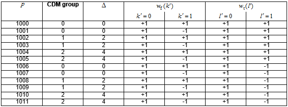
- Configuration Type 2 : 2 pairs(4 Resource Elements:RE) of DMRS are dispersed in one OFDM symbol/one RB at the interval of 6 REs (6n). The two RE in each pare are apart at the interval of 1 RE(k'), meaning that the two REs in each pair are contiguous. This supports 12 DMRS ports in case of double-symbol DMRS(port 1000~1011) and 8 DMRS ports in case of single symbol DMRS(port 1000~1007). See Table 7.4.1.1.2-2 and Table 7.4.1.1.2-5 for further details.
- PDSCH mapping type changes the location pattern in time domain
- PDSCH Mapping Type A : In this type, the DMRS symbol can start only at symbol 2 or 3 regardless of PDSCH start and length. It implies this cannot be used when PDSCH start symbol is greater than 3. This is related to the row 'Type A' in PDSCH SLIV table. This type is used for slot based scheduling.
- PDSCH Mapping Type B : In this type, the DMRS symbol can start at the first PDSCH symbol regardless of PDSCH start. This is related to the row 'Type B' in PDSCH SLIV table. This type is used for mini-slot based scheduling
Another points you would notice would be
- frequency domain location(k) is determined by equation(formula) as shown below
- time domain location(l) is determined by a predefined table and predefined value.
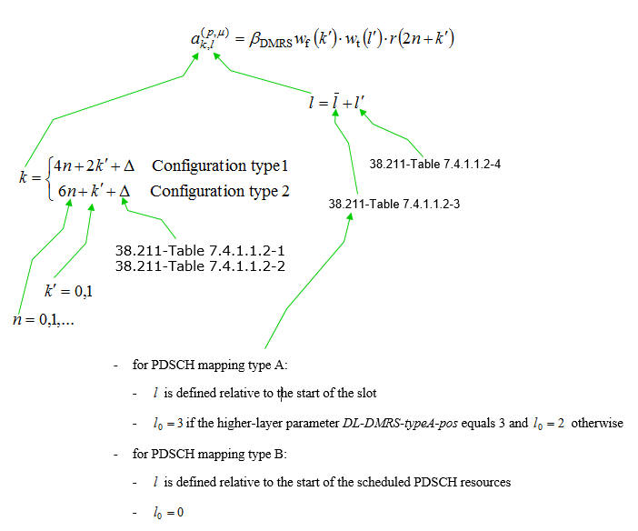
Example 01 > Configuration type 1, n = {0,1,2}, k'={0,1}, port = 1000 (i.e, delta = 0 according to 38.211-Table 7.4.1.1.2-1)
- When n = 0, k'=0, delta = 0, k --> 0 (4*0 + 2*0 + 0)
- When n = 0, k'=1, delta = 0, k --> 2 (4*0 + 2*1 + 0)
- When n = 1, k'=0, delta = 0, k --> 4 (4*1 + 2*0 + 0)
- When n = 1, k'=1, delta = 0, k --> 6 (4*1 + 2*1 + 0)
- When n = 2, k'=0, delta = 0, k --> 8 (4*2 + 2*0 + 0)
- When n = 2, k'=1, delta = 0, k --> 10 (4*2 + 2*1 + 0)
Example 02 > Configuration type 2, n = {0,1}, k'={0,1}, port = 1000 (i.e, delta = 0 according to 38.211-Table 7.4.1.1.2-2)
- When n = 0, k'=0, delta = 0, k --> 0 (6*0 + 0 + 0)
- When n = 0, k'=1, delta = 0, k --> 1(6*0 + 1 + 0)
- When n = 1, k'=0, delta = 0, k --> 6 (6*1 + 0 + 0)
- When n = 1, k'=1, delta = 0, k --> 7 (6*1 + 1 + 0)
The result of this equation is well summarized by Ref [1] as shown below. If you really want to understand the details of this equation, fill out the resource grid on your own by hand. Since this is simple formula, you would be able to calculate the position of this DMRS RE by hand.
Tables
Followings are various tables that are used in Sequence Generation and Resource Element Mappaing shown above. Neither of those sections can be followed without them, because the equations there reference the tables rather than repeating their contents. They are reproduced here so the reader does not have to open 38.211 alongside this page.
They are reproduced here because the equations above are unreadable without them. Two of the tables give the resource element pattern for each port, and two give the symbol positions for a given dmrs-AdditionalPosition. The last one supplies the time index used by the code that separates ports sharing a symbol.
< 38.211 - Table 7.4.1.1.2-1: Parameters for PDSCH DM-RS configuration type 1 >
< 38.211 - Table 7.4.1.1.2-2: Parameters for PDSCH DM-RS configuration type 2 >
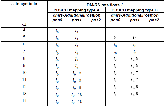
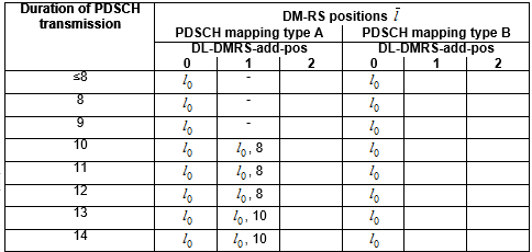
< 38.211 - Table 7.4.1.1.2-3: PDSCH DM-RS positions  for single-symbol DM-RS >
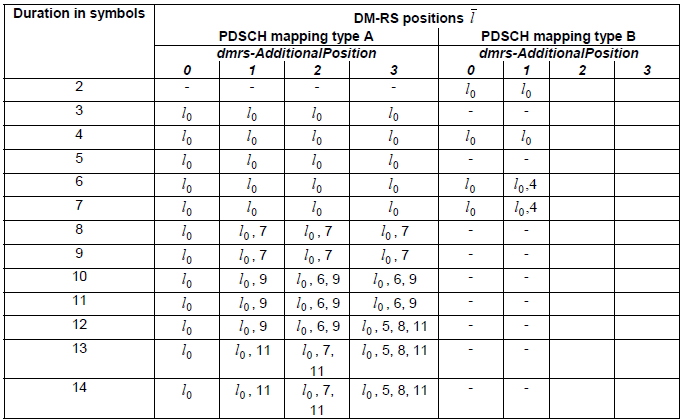
This table shows how the location of single symbol DMRS(i.e, maxlength = 1) is determined for each PDSCH mapping type. It shows that for mapping type B there is only one case where additional dmrs can be used. It is when the length of PDSCH is 7 symbols. For mapping type A, one additional dmrs can be used when PDSCH symbol length is equal to or greather than 9, two additional dmrs can be used when PDSCH symbol length is equal to or greather than 10 and three additional dmrs can be used when PDSCH symbol length is equal to or greather than 12.
<38.211-v15.2 Table 7.4.1.1.2-3:PDSCH DM-RS positions i for single-symbol DM-RS >
<38.211-v19.1 Table 7.4.1.1.2-3:PDSCH DM-RS positions i for single-symbol DM-RS >
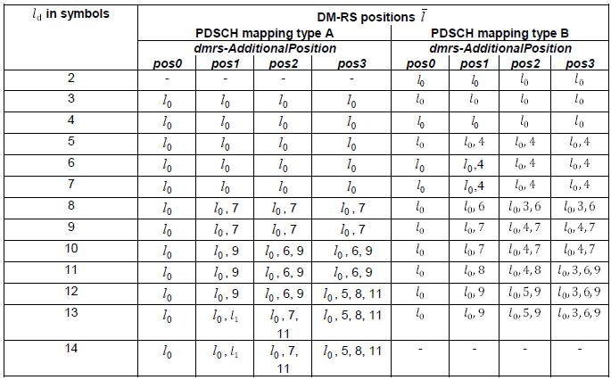
<38.211-v19.1 Table 7.4.1.1.2-4:PDSCH DM-RS positions i for double-symbol DM-RS >
- the case dmrs-AdditionalPosition equals to 'pos3' is only supported when dmrs-TypeA-Position is equal to 'pos2';
- ld = 3 and ld = 4 symbols in Tables 7.4.1.1.2-3 and 7.4.1.1.2-4 respectively is only applicable when dmrs-TypeA-Position is equal to 'pos2';
- single-symbol DM-RS, l1 = 11 except if all of the following conditions are fulfilled in which case l1 = 12:
- the higher-layer parameter lte-CRS-ToMatchAround, lte-CRS-PatternList1, or lte-CRS-PatternList2 is configured; and
- the higher-layer parameter dmrs-AdditionalPosition is equal to 'pos1' and l0 = 3; and
- the UE has indicated it is capable of additionalDMRS-DL-Alt
< 38.211 - Table 7.4.1.1.2-4: PDSCH DM-RS positions for double-symbol DM-RS >
This table shows how the location of double symbol DMRS(i.e, maxlength = 2) is determined for each PDSCH mapping type. It shows that for mapping type B additional dmrs cannot be used. For mapping type A, only one additional dmrs can be used when PDSCH symbol length is equal to or greather than 10. Regardless of mapping type, 2 additional dmrs cannot be used.
< 38.211 -Table 7.4.1.1.2-5: PDSCH DM-RS time index l' and antenna ports p >
This table shows how many DMRS antenna port can be used for each DMRS configuration (i.e, Configuration type and max length of DMRS symbols). As shown here, when the max dmrs symbol lengh is 1, maximum 4 dmrs antenna ports can be used for configuration type 1 and max 6 dmrs port can be used for configuration type 2. When the max dmrs symbol length is 2, 8 dmrs antenna port can be used for configuration type 1 and 12 dmrs antenna port can be used for configuration type 2.
This information is used to select which Antenna port table is associated in DCI 1_1 for setting up SISO/MIMO

Reference
[1] Wireless Technology Evolution - Transition from 4G to 5G : 5G Americas