Let's start with the two names, because they are easy to confuse. ENDC and NEDC both describe LTE and NR carrying traffic for the same UE at the same time. The only difference between them is which radio is in charge. The summary below is the short version, and the rest of this page works through it in detail.
|
Interworking with LTE - NSA / ENDC in Detail
This is about one of NR deployment options where LTE work as a master and NR work as a secondary cell (In 3GPP terms, this is about EN-DC (EUTRA-NR Dual Connectivity) / MR-DC with EPC as described in 37.340). In this configuration, UE get connected to LTE network first and then connected to NR via RRC Connection Reconfiguration process. Further details on lower layer process is yet to be studied, but just looking into the conentents of RRCConnectionReconfiguration would give you some general idea about the mechanism.
Two things are worth fixing in mind before the detail starts. The first is that EN-DC keeps the EPC. The core network is the one LTE already had, and NR contributes radio capacity and nothing else. That is what makes EN-DC a deployment option rather than a new system, and it is why the signalling further down is LTE RRC carrying NR RRC inside it.
The second is that the LTE cell anchors everything the network cares about. The UE registers through LTE, its NAS connection runs over LTE, and RRC signalling reaches it from the LTE eNB. NR is added afterwards, onto a connection that already exists. Nothing on this page describes a UE camping on NR first, because in EN-DC it never does.
|
|
Overall Network Architecture
Overall RAN architecture of EN-DC can be illustrated as below (this is based on 37.340 - 4.3.1 and 4.3.2). As you see here, UE is communicating with both LTE eNB and NR gNB in Radio side, but all those communication (signaling and data) are going through LTE core network. Though not shown in this illustration, I would point out that LTE eNB and NR gNB are using their own PHY/MAC (i.e, independent MAC Scheduler)).
As you see here, in case of data plane both Master Node(LTE) and Secondary Node(gNB) has direct interface with LTE corenetwork(S-GW), but in case of control plane only Master Node(LTE) has direct interface with LTE core network(MME).
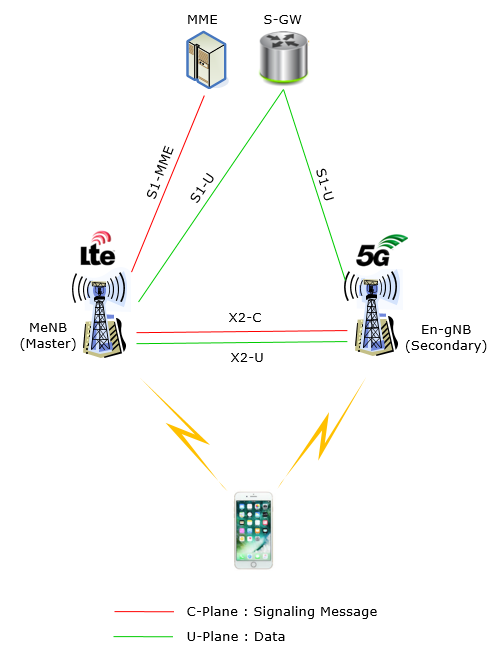
Now let's read the picture. If you take a close look at the illustration and just describe it in words, you would get the descrition as follows. If you don't like reading (like me :), just take 10 minutes (not 10 seconds) and look thorugh each and every part and lines of the picture.
- For C-Plane
- There is an interface between MN(Master Node : MeNB in this csae) and the SN (Secondary Node : En-gNB in this case). This interface is called X2-C.
- There is an interface between MN and CN(Core Network : MME in this case). This interface is called S1-MME.
- There is NO direct interface(connection) between SN and CN
- For U-Plane
- There is an interface between MN(Master Node : MeNB in this csae) and the SN (Secondary Node : En-gNB in this case). This interface is called X2-U.
- There is an interface between MN and CN(Core Network : MME in this case). This interface is called S1-U
- There is an interface(connection) between SN and CN. This interface is called S1-U.
Overall Layer 2 Architecture
Following is based on 37.340 - Figure 4.2.2-3 and Figure 4.2.2-1. As mentioned before, there are roughly two options when LTE and NR interplay. One option is to make LTE as a master and NR as a slave. The other option is to make NR as a master and LTE as a slave. In real deployment, especially at the early deployment, the first option (i.e, LTE Master and NR Slave) would be the major deployment option. This illustration is also to show the overal radio stack structure of LTE Master and NR Slave.
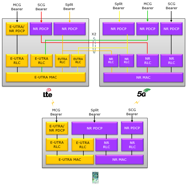
Read the picture in three blocks. The left grey box is the LTE node, the right one is the NR node, and the box at the bottom is the UE. X2 runs between the two network boxes, and the coloured lines crossing it are bearers whose PDCP sits on one node while their RLC sits on the other.
The row of labels along the top is the part to study. MCG Bearer, SCG Bearer and Split Bearer each enter the stack at a different PDCP entity, and that entry point is the whole definition of the bearer type. Notice which PDCP blocks are which. Only the leftmost block on the LTE node is drawn as E-UTRA/NR PDCP. Every other PDCP block in the drawing, on both nodes and in the UE, is NR PDCP.
That asymmetry is deliberate. An MCG bearer may keep LTE PDCP, because it is the bearer that existed before NR arrived. Anything anchored at the NR node, or split across both nodes, needs NR PDCP instead.
The UE stack mirrors the network : the bottom box carries the same PDCP, RLC and MAC entities as the two network boxes together. The UE has to terminate whichever bearer type it is given.Two MACs, never one : E-UTRA MAC and NR MAC stay separate everywhere in the picture, which is what makes this dual connectivity rather than carrier aggregation.PDCP is where the split happens : every line crossing X2 leaves a PDCP block and arrives at an RLC block. The bearer is divided above RLC and never below it.E-UTRA/NR PDCP appears once per stack : it is the only block that can be either, and it belongs to the MCG bearer.
Various types of Bearer for LTE-NR Interworking (EN-DC)
In terms of Over The Air(OTA) and Physical Layer perspective, LTE-NR interworking (EN-DC) in NSA(Non-StandAlone) is only one possibility (assuming that LTE always becomes the Anchor), but with the same OTA/Physical layer there can still be multiple possibilities of implementing higher layer bearer.
38.331 - 5.3.1.1 RRC connection control states as follows :
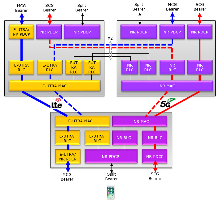
In case of EN-DC, the SCG cells use another RAT, namely NR. When configured with EN-DC, user data carried by a DRB may either be transferred via MCG, via NR SCG or via both MCG and NR SCG. Also RRC signalling carried by a SRB may either be transferred via MCG or via both MCG and NR SCG. When DRBs and SRBs are configured with transmission via both MCG and SCG, duplication may be used in both DL and UL.
I just tried to turn this statement into illustration as follows (This illustration is based on 37.340 - Figure 4.2.2-3 and Figure 4.2.2-1) :
The statement 'DRB may either be transferred via MCG, via NR SCG or via both MCG and NR SCG' can be illustrated as follows.
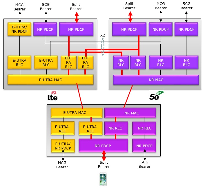
There is another bearer type called split Bearer (or split DRB). It can be illustrated as follows. You may find more details about this in Split Bearer page.
Types of NR(SCG) addition in EN-DC(LTE+NR Interworking)
In ENDC(Eutra NR Dual Connectivity), LTE would become a MCG(Master Cell Group) and NR would become a SCG(Secondary Cell Group). MCG work as the anchor and UE performs initial registration to this anchor cell group, and this anchor cell add one or more Secondary Cells (SCG). In 36.331-5.3.1.1, there are three different types(ways) of adding SCGs to the LTE anchor cell as follows.
- Perform RA Procedure to PScell
- Reset NR MAC
- Re-establish NR RLC
- Re-establish NR PDCP
- Refresh NR SCG security
- Perform RA to the PSCell,
- Reset NR MAC
- Re-establish NR RLC re-establishment and
- Re-establish PDCP data recovery (for AM DRB)
- Does not perform RA to the PScell
- Does not refresh NR SCG security
- Reset NR MAC
- Re-establish NR RLC
Type 1 : Reconfiguration with sync and key change
Type 2 : Reconfiguration with sync but without key change
Type 3 : Regular NR SCG reconfiguration without Sync / SCG Security
The three types differ in how much of the NR stack is torn down and rebuilt, and the cost rises steeply from Type 3 up to Type 1. Type 3 is a configuration change on an SCG that keeps running. Type 2 rebuilds the lower layers and re-runs random access, but leaves the keys alone. Type 1 does all of that and refreshes the SCG security as well.
That ordering is the useful part when you are reading a log. A random access to the PSCell means the network chose Type 1 or Type 2, and never Type 3. If the SCG keys change as well, it was Type 1. A reconfiguration that touches neither is Type 3, and the UE keeps transmitting on the SCG throughout.
Only Type 1 changes the SCG keys : that is the one case where sk-Counter has to move, so an unchanged counter rules Type 1 out.Random access separates Type 3 from the other two : Types 1 and 2 both send the UE back through RACH on the PSCell, and Type 3 does not.Type 3 is the cheap one and the common one : most SCG reconfigurations in a running connection change parameters without resetting MAC or re-establishing RLC.
Overall Signaling Procedure
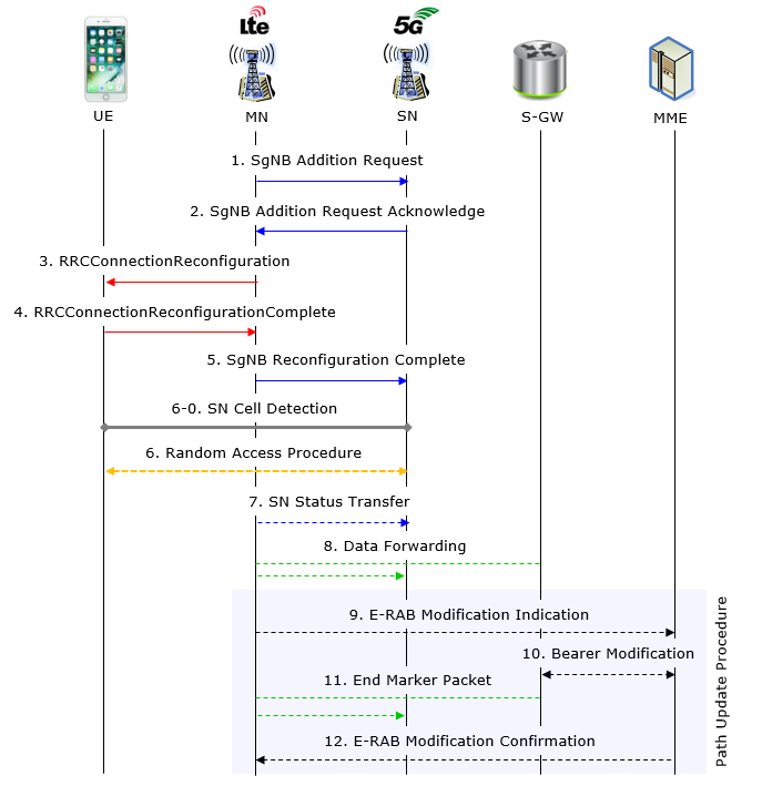
This section is about how to add NR cell(Secondary Node) to an existing LTE Cell.(Master Note). Overall signaling flow is illustrated below. This flow is based on 37.340 - 10.2.1 except the step 6-0 which is added by me. As you may notice,the process is iniated by MN (Master Node : LTE eNB in this case) and final confirmation is done by MME.
< 37.340 - Figure 10.2.1-1: Secondary Node Addition procedure >
- E-RAB Characteristics (E-RAB Parameters, TNL address information)
- The requested SCG configuration information including the entire UE capabilities and UE capability coordination result
- The latest measurement result for SN to choose
- Securiy Information to enable SRB3
- In case of bearer option that requires X2-U between MN and SN
- X2-U TNS address information
- In case of SN terminated split bearers,
- the maximum supportable QoS level
- Allocate the necessary radio resources transport network resources
- decides Pscell and other SCG Scells and provide the new SCG radio resource configuration to MN
- In case of bearer options that requires X2-U between MN and SN
- provides X2-U TNS address informations
- In case of SCG radio resources being requested
- provide SCG radio resource configuration
Following is a summary of overall NSA procedure which would give you more practical sense. This would be the most common NSA protocol sequence that you may see from RRC/NAS log.
|
Direction |
Message/Procedure |
Comments |
|
UE <-- NW |
SIB2 with 5G support indication |
See this note for an example |
|
UE <-> NW |
< LTE Initial Attach Start> |
|
|
|
... |
|
|
UE <-- NW |
UECapabilityInformqtionEnquiry |
NW request UE to notify NR capability |
|
UE --> NW |
UECapabilityInformation |
UE Report NR capability. See this note |
|
|
... |
|
|
|
< LTE Initial Attach Complete> |
|
|
UE <-- NW |
RrcConnectionReconfiguration for NR Cell Measurement |
See this note for an example |
|
UE --> NW |
RrcConnectionReconfigurationComplete |
|
|
UE --> NW |
MeasurementReport with NR Cell Measurement |
See this note for an example |
|
UE <-- NW |
RrcConnectionReconfiguration for NR Addition |
See this note for the details |
|
UE --> NW |
RrcConnectionReconfigurationComplete |
|
|
UE <-> NW |
Peform RACH process to NR Cell |
See this note for an example |
LTE RRC Configuration
The major role of RRC in LTE-NR Interworking(more specifically ENDC) is to add NR as a secondary cell to LTE Anchor cell. The major IE(information elements) related to this process are
- nr-Config
- nr-SecondaryCellGroupConfig
- nr-RadioBearerConfig1
These few IEs has very complicated structures in it and carries so much information. Basically they carries all the information that combines MIB, SIB and RRC Configuration messages in standalone NR. I will take a while to get the detailed understanding on each and every elements of informations in it. Followings are rough summary of informations carried by the RRC Connection Reconfiguration message.
|
Function (Information) |
Description |
|
Frequency and Bandwidth in NR Downlink |
spCellConfigCommon.frequencyInfoDL spCellConfigCommon.initialDownlinkBWP |
|
Frequency and Bandwidth in NR Uplink |
spCellConfigCommon.uplinkConfigCommon.frequencyInfoUL spCellConfigCommon.uplinkConfigCommon.initialUplinkBWP |
|
PRACH to NR |
spCellConfigCommon.uplinkConfigCommon.initialUplinkBWP.rach-ConfigCommon |
|
PDCCH Configuration to decode RAR(PDSCH) |
spCellConfigCommon.initialDownlinkBWP.pdcch-ConfigCommon |
|
PDSCH Configuration to send RAR(PDSCH) |
spCellConfigCommon.initialDownlinkBWP.pdsch-ConfigCommon |
|
PUSCH Configruation for Common Channel |
spCellConfigCommon.uplinkConfigCommon.initialUplinkBWP.PUSCH-ConfigCommon |
|
PDCCH Configuration for dedicated channels (msg4 and onwards) |
spCellConfigDedicated.initialDownlinkBWP.pdcch-Config |
|
PDSCH Configuration for dedicated channels (msg4 and onwards) |
spCellConfigDedicated.initialDownlinkBWP.pdsch-Config |
|
PUCCH Configruation for Dedicated Channel (msg4 Ack/Nack and onwards) |
spCellConfigDedicated.initialDownlinkBWP.pdcch-Config |
|
PUSCH Configruation for Dedicated Channel (msg4 Ack/Nack and onwards) |
spCellConfigDedicated.initialDownlinkBWP.pdcch-Config |
|
tdd UL/DL Configuration |
spCellConfigCommn.tdd-UL-DL-ConfigurationCommon spCellConfigDedicated.tdd-UL-DL-ConfigurationDedicated |
Following is based on
RRCConnectionReconfiguration-v1430-IEs ::= SEQUENCE {
    sl-V2X-ConfigDedicated-r14                  SL-V2X-ConfigDedicated-r14                              OPTIONAL,   -- Need ON
    sCellToAddModListExt-v1430                  SCellToAddModListExt-v1430                              OPTIONAL,   -- Need ON
    perCC-GapIndicationRequest-r14              ENUMERATED{true}                                        OPTIONAL,   -- Need ON
    systemInformationBlockType2Dedicated-r14    OCTET STRING (CONTAINING SystemInformationBlockType2)   OPTIONAL,   -- Cond nonHO
    nonCriticalExtension                        RRCConnectionReconfiguration-v1510-IEs                  OPTIONAL
}

RRCConnectionReconfiguration-v1510-IEs ::= SEQUENCE {
    nr-Config-r15                               CHOICE {
        release                                     NULL,
        setup                                       SEQUENCE {
            endc-ReleaseAndAdd-r15                      BOOLEAN,
            nr-SecondaryCellGroupConfig-r15             OCTET STRING            OPTIONAL,   -- Need ON
            p-MaxEUTRA-r15                              P-Max                   OPTIONAL    -- Need ON
        }
    }                                                                                                   OPTIONAL,   -- Need ON
    sk-Counter-r15                              INTEGER (0.. 65535)                                     OPTIONAL,   -- Need ON
    nr-RadioBearerConfig1-r15                   OCTET STRING                                            OPTIONAL,   -- Need ON
    nr-RadioBearerConfig2-r15                   OCTET STRING                                            OPTIONAL,   -- Need ON
    tdm-PatternConfig-r15                       TDM-PatternConfig-r15                                   OPTIONAL,   -- Cond FDD-PCell
    nonCriticalExtension                        RRCConnectionReconfiguration-v1530-IEs                  OPTIONAL
}
Draft naming, not present in
RRCConnectionReconfiguration-v15x0-IEs ::= SEQUENCE {
    endc-Config-r15                     SEQUENCE {
        scg-ConfigReleaseNR-r15             BOOLEAN,
        sk-Counter-r15                      INTEGER (0.. 65535)     OPTIONAL,   -- Need ON
        nr-SecondaryCellGroupConfig-r15     OCTET STRING            OPTIONAL,   -- Need ON
        nr-RadioBearerConfig-r15            OCTET STRING            OPTIONAL,   -- Need ON
        nr-RadioBearerConfigS-r15           OCTET STRING            OPTIONAL,   -- Need ON
        tdm-PatternSingle-Tx-r15            SEQUENCE {
            subframeAssignment-r15              SubframeAssignment-r15,
            harq-Offset-r15                     INTEGER (0.. 9)     OPTIONAL    -- Need ON
        }                                                           OPTIONAL    -- Need ON
    }                                                               OPTIONAL    -- Need ON
    nonCriticalExtension                SEQUENCE {}                 OPTIONAL
}
nr-SecondaryCellGroupConfig1-r15,nr-SecondaryCellGroupConfig2-r15 : Includes NR RRCReconfiguration message.
The field includes the configuration of RBs configured with NR PDCP.
nr-RadioBearerConfig : Include NR RadioBearerConfig. Mainly for DRB, EPS, NR PDCP Configuration
Draft naming, not present in
RRCConnectionResume-v15x0-IEs ::= SEQUENCE {
    sk-Counter-r15                      INTEGER (0.. 65535)         OPTIONAL,   -- Need ON
    nr-RadioBearerConfig-r15            OCTET STRING                OPTIONAL,   -- Need ON
    nr-RadioBearerConfigS-r15           OCTET STRING                OPTIONAL,   -- Need ON
    nonCriticalExtension                SEQUENCE {}                 OPTIONAL
}
The published form of that last one carries the same two octet strings, under the names used everywhere else in the message. It also chains to a Release 15.3 extension instead of ending in an empty SEQUENCE.
Following is based on
RRCConnectionResume-v1510-IEs ::= SEQUENCE {
    sk-Counter-r15                      INTEGER (0.. 65535)         OPTIONAL,   -- Need ON
    nr-RadioBearerConfig1-r15           OCTET STRING                OPTIONAL,   -- Need ON
    nr-RadioBearerConfig2-r15           OCTET STRING                OPTIONAL,   -- Need ON
    nonCriticalExtension                RRCConnectionResume-v1530-IEs   OPTIONAL
}
Example >
As mentioned above, RRC Connection Reconfiguration in LTE for Adding NR Cell carries only a couple of container that carries a huge tree of NR RRC message. Due to the complicated RRC structure in NR, I found it difficult to put the whole structure and description of any NR RRC message in a single page. In this example, you will see a couple of starting points of NR RRC part as shown below and you should follow the link until you reach the final destination.
NOTE : If you want to see the contents of full log with Amarisoft Log viewer, go to LogAnalysis section and click on 'Sample Log' in this tutorial of Amarisoft TechAcademy.
Field tree of the LTE
rrcConnectionReconfiguration
measConfig
mobilityControlInfo
dedicatedInfoNASList
radioResourceConfigDedicated
nonCriticalExtension
laterNonCriticalExtension
nonCriticalExtension
otherConfig-r9
fullConfig-r9
nonCriticalExtension
sCellToReleaseList-r10
sCellToAddModList-r10
nonCriticalExtension
systemInformationBlockType1Dedicated-r11
nonCriticalExtension
wlan-OffloadInfo-r12
scg-Configuration-r12
sl-SyncTxConfrol-r12
sl-DiscConfig-r12
sl-CommonConfig-r12
nonCriticalExtension
sCellToReleaseListExt-r13
sCellToAddModListExt-r13
lwa-Configuration-r13
lwip-Configuration-r13
rdwi-Configuration-r13
nonCriticalExtension
sl-V2X-ConfigDedicated-r14
sCellToAddModListExt-v1430
perCC-GapIndicationRequest-r14
systemInformationBlockType2Dedicated-r14
nonCriticalExtension
nr-Config-r15
endc-ReleaseAndAdd-r15
nr_SecondaryCellGroupConfig-r15
cellGroupID
rlc-BearerToAddModList
mac-CellGroupConfig
physicalCellGroupConfig
spCellConfig
servCellIndeix
reconfigurationWithSync
spCellConfigCommon
physCellId
frequencyInfoDL
initialDownlinkBWP
genericParameters
pdcch_ConfigCommon
setup
commonControlResources
commonSearchSpaces
searchSpaceSIB1
searchSpaceOtherSystemInformation
pagingSearchSpace
ra_ConfrolResourceSet
ra_SearchSpace
pdsch_ConfigCommon
setup
="5G_PDSCH.html#PDSCH_Config_pdsch_AllocationList" target="_self">pdsch_AllocationList
uplinkConfigCommon
frequencyInfoUL
initialUplinkBWP
supplementaryUplinkConfig
supplementaryUplinkConfig
ssb_PositionsInBurst
ssb_periodicityServingCell
dmrs_TypeA_Position
lte_CRS_ToMatchAround
rateMatchPatternToAddModList
rateMatchPatternToReleaseList
subcarrierSpacing
tdd_UL_DL_ConfigurationCommon
referenceSubcarrierSpacing
dl_UL_TransmissionPeriodicity
nrofDownlinkSlots
nrofDownlinkSymbols
nrofUplinkSlots
nrofUplinkSymbols
tdd_UL_DL_ConfigurationCommon2
ss_PBCH_BlockPower
newUE_Identity
t304
rach_ConfigDedicated
rlf-TimersAndConstants
rlmInSyncOutOfSyncThreshold
spCellConfigDedicated
tdd_UL_DL_ConfigurationDedicated
initialDownlinkBWP
pdcch_Config
pdsch_Config
sps_Config
radioLinkMonitoringConfig
downlinkBWP_ToReleaseList
downlinkBWP_ToAddModList
firstActiveDownlinkBWP_Id
bwp_InactivityTimer
defaultDownlinkBWP_Id
uplinkConfig
initialUplinkBWP
uplinkBWP_ToReleaseList
uplinkBWP_ToAddModList
firstActiveUplinkBWP_Id
pusch_ServingCellConfig
supplementaryUplink
pdsch_ServingCellConfig
csi_MeasConfig
carrierSwitching
sCellDeactivationTimer
crossCarrierScheduleConfig
tag_Id
ue_BeamLockFunction
pathlossReferenceLinking
p_MaxEUTRA-r15
sk-Counter-r15
nr-RadioBearerConfig1-r15
nr-RadioBearerConfig2-r15
tdm-PatternConfig-r15
nonCriticalExtension
Measurement (LTE-NR Measurement)
In real operation, it is expected for LTE to perform the measurement of the NR cell before it tries adding it. When it comes to measurement, first we need to think of what kind of measurement event to be used. And since this is interfrequency/interRAT from the point of LTE we need to think of measurement gap.
In terms of measurement event, we are using the existing event B1 and B2 and not new event is defined for NR measurement(see here for the details), but in terms of measurement gap, we got a lot of new gap patterns for NR measurement(see here for the details).
NOTE : If you want to see the contents of full log with Amarisoft Log viewer, go to LogAnalysis section and click on 'Sample Log' in this tutorial of Amarisoft TechAcademy.
Example 01 >
Following example message is from Amari Callbox and a commercial UE. I am just putting the measurement related part here and refer to this file for the full contents of the message.
Decoded RRC message,
  message c1: rrcConnectionReconfiguration: {
    rrc-TransactionIdentifier 0,
    criticalExtensions c1: rrcConnectionReconfiguration-r8: {
      measConfig {
        measObjectToAddModList {
          {
            measObjectId 1,
            measObject measObjectEUTRA: {
              carrierFreq 300,
              allowedMeasBandwidth mbw100,
              presenceAntennaPort1 TRUE,
              neighCellConfig '01'B
            }
          },
          {
            measObjectId 2,
            measObject measObjectNR-r15: {
              carrierFreq-r15 632256,
              rs-ConfigSSB-r15 {
                measTimingConfig-r15 {
                  periodicityAndOffset-r15 sf20-r15: 0,
                  ssb-Duration-r15 sf1
                },
                subcarrierSpacingSSB-r15 kHz30
              },
              quantityConfigSet-r15 1,
              bandNR-r15 setup: 78
            }
          }
        },
        reportConfigToAddModList {
          {
            reportConfigId 1,
            reportConfig reportConfigInterRAT: {
              triggerType event: {
                eventId eventB1-NR-r15: {
                  b1-ThresholdNR-r15 nr-RSRP-r15: 56,
                  reportOnLeave-r15 FALSE
                },
                hysteresis 0,
                timeToTrigger ms100
              },
              maxReportCells 8,
              reportInterval ms120,
              reportAmount r1,
              reportQuantityCellNR-r15 {
                ss-rsrp TRUE,
                ss-rsrq TRUE,
                ss-sinr TRUE
              }
            }
          }
        },
        measIdToAddModList {
          {
            measId 1,
            measObjectId 2,
            reportConfigId 1
          }
        },
        quantityConfig {
          quantityConfigEUTRA {
            filterCoefficientRSRP fc3
          },
          quantityConfigNRList-r15 {
            {
              measQuantityCellNR-r15 {
                filterCoeff-RSRP-r15 fc3
              }
            }
          }
        },
        measGapConfig setup: {
          gapOffset gp0: 16
        }
      },
......
}

  message c1: measurementReport: {
    criticalExtensions c1: measurementReport-r8: {
      measResults {
        measId 1,
        measResultPCell {
          rsrpResult 69,
          rsrqResult 30
        },
        measResultNeighCells measResultNeighCellListNR-r15: {
          {
            pci-r15 500,
            measResultCell-r15 {
              rsrpResult-r15 79,
              rsrqResult-r15 65,
              rs-sinr-Result-r15 89
            }
          }
        }
      }
    }
  }
}
SCG Failure
Various type of failure can happen during NR addition after UE recieves RRC Connection Reconfiguration. When this happens, UE send SCG Failure Information message with various failure cause as listed below. This is based on 38.331 5.7.3.3. You should see 38.331 v15.4 or higher)
|
Failure type of SCG-FailureInformation |
||
|
|
t310-Expiry |
This is triggered when UE is experience consecutive Out-Of_Sync at low layer. (Refer to 38.331-7.1.1 for further details.) Related Parameter : t310, n310, n311 |
|
|
t312-Expiry |
(Applicable for failureType-v1610). Not receiving N311 consecutive in-sync indications from lower layers for the SpCell, receiving RRCReconfiguration with reconfigurationWithSync for that cell group after measurement report is triggered ( Refer to 38.331-7.1.1 for further details.) |
|
|
synchReconfigFailure-SCG |
This is triggered when initial synchronization failed. It is triggered when UE fails to complete NR RACH until T304 expires Related Parameter : t304 (see 38.331 - 5.3.5.8.3 and 7.1.1 for further details) |
|
|
randomAccessProblem |
This is triggered when random access process has failed Related Parameter : PreambleTransMax (see 38.331 - 5.7.3.3 for further details) |
|
|
rlc-MaxNumRetx |
This is triggered when the maximum number of retransmissions has been reached Related Parameter : maxRetxThreshold (see 38.331 - 5.7.3.3 for further details) |
|
|
srb3-IntegrityFailure |
This is triggered when SRB3 Integrity fails (see 38.331 - 5.7.3.3 for further details) |
|
|
scg-reconfigFailure |
This is triggered when Reconfiguration message is not compatible with UE (see 38.331 - 5.7.3.3 for further details) |
Those values are the contents of one field in one message, and the message is worth naming precisely, because EN-DC does not use the obvious one.
Which Message Carries the Report
38.331-5.7.3.2 sends the UE down two different paths at the end of the procedure. In (NG)EN-DC the UE transmits
That split follows from where the report has to arrive. The MCG is LTE, so the only surviving signalling path at the moment of failure is SRB1 on the LTE anchor. The report therefore has to be an LTE message, and the eNB reads it directly rather than forwarding a container it cannot decode.
Following is based on
SCGFailureInformationNR-r15-IEs ::=     SEQUENCE {
    failureReportSCG-NR-r15                 FailureReportSCG-NR-r15             OPTIONAL,
    nonCriticalExtension                    SCGFailureInformationNR-v1590-IEs   OPTIONAL
}

FailureReportSCG-NR-r15 ::=             SEQUENCE {
    failureType-r15                         ENUMERATED {
                                                t310-Expiry, randomAccessProblem,
                                                rlc-MaxNumRetx,
                                                synchReconfigFailureSCG, scg-reconfigFailure,
                                                srb3-IntegrityFailure, dummy},
    measResultFreqListNR-r15                MeasResultFreqListFailNR-r15        OPTIONAL,
    measResultSCG-r15                       OCTET STRING                        OPTIONAL,
    ...,
    [[  locationInfo-r16                    LocationInfo-r10                    OPTIONAL,
        logMeasResultListBT-r16             LogMeasResultListBT-r15             OPTIONAL,
        logMeasResultListWLAN-r16           LogMeasResultListWLAN-r15           OPTIONAL,
        failureType-v1610                   ENUMERATED {t312-Expiry, scg-lbtFailure,
                                                beamFailureRecoveryFailure, bh-RLF-r16,
                                                beamFailure-r17,
                                                spare3, spare2, spare1}         OPTIONAL
    ]],
    [[  previousPSCellId-r19                SEQUENCE {
            physCellId-r19                      PhysCellIdNR-r15,
            carrierFreq-r19                     ARFCN-ValueNR-r15
        }                                                                       OPTIONAL,
        failedPSCellId-r19                  SEQUENCE {
            physCellId-r19                      PhysCellIdNR-r15,
            carrierFreq-r19                     ARFCN-ValueNR-r15
        }                                                                       OPTIONAL,
        timeSCG-Failure-r19                 INTEGER (0..1023)                   OPTIONAL
    ]]
}
Two things in that definition explain the table above. There are
38.331-5.7.3.3 explains the odd consequence of that arrangement. When the cause is T312 expiry, the UE sets failureType-v1610 to t312-Expiry and sets the original failureType to
The rest of the message is there so the eNB can decide what to do next. Field measResultFreqListNR carries the best measured NR cells per frequency, ordered best first, using RSRP where it is available and RSRQ or SINR otherwise. Field measResultSCG carries the NR measurement results as an octet string. Together they tell the anchor whether another NR cell is worth trying.
The Release 19 group at the end exists for mobility robustness optimisation. It records the previous PSCell, the PSCell that failed, and how long elapsed since the reconfiguration with sync that led to the failure. Those three make it possible to tell a badly timed PSCell change from a cell that was simply out of coverage.
EN-DC reports on the LTE side : the message is SCGFailureInformationNR from 36.331, so look for it on SRB1 towards the eNB and not on any NR bearer.There are two failure type fields : anything newer than Release 15 arrives in failureType-v1610, and the table above lists only one of those four extension values.A T312 failure carries a meaningless r15 cause : the specification lets the UE set it to any value, so trust failureType-v1610 when both fields are present.The measurement results are the actionable part : they are what lets the eNB choose a replacement PSCell rather than abandoning NR.
What the UE Does When the SCG Fails
The report is only half of it. Before the UE sends anything it suspends the secondary leg. Knowing exactly how far that goes tells you what a trace should look like afterwards.
38.331-5.7.3.2 lists five triggers. The first is radio link failure on the SCG. The second is beam failure of the PSCell, but only while the SCG is deactivated. The third is reconfiguration with sync failure, and the fourth is SCG configuration failure. The fifth is an integrity check failure reported by SCG lower layers for SRB3. The procedure only runs when neither MCG nor SCG transmission is already suspended.
On initiation the UE suspends SCG transmission for all SRBs, DRBs and BH RLC channels, and resets the SCG MAC. It stops T304 for the SCG if it is running, and it stops evaluating any conditional PSCell change or addition it had been given. Then it sends the report.
Notice what is absent from that list. Nothing touches the MCG. The LTE connection stays up, the UE keeps its RRC connection and its NAS connection, and user data keeps flowing on any MCG bearer. An SCG failure in EN-DC is a lost radio leg rather than a dropped call, which is exactly why the anchor design was chosen.
The MCG survives an SCG failure : the UE suspends the SCG and reports over LTE, so the connection continues on the anchor while NR is rebuilt or abandoned.Suspend and reset, not release : the SCG configuration is still held by the UE after the failure, and it is the network that decides whether to release, change or re-add.Conditional PSCell changes are cancelled too : any CPC or CPA evaluation stops at the same moment, so a prepared target will not fire after the failure.Beam failure only triggers this while the SCG is deactivated : an active SCG handles beam failure through its own recovery procedure instead.
NOTE : If you speak / understand Korean, you may refer to this YouTube by Sean Mobile Channel(@22:00)
Carrier Aggregation Setup in NR
After you add NR cell to LTE Anchor completing ENDC, you can add other NR cells to establish Carrer Aggregation(CA). The addition of secondary NR cells can be done at the same step as ENDC establishment or done separately after the ENDC Setup. This NR CA process is very similar to LTE CA establishment process. Overall procedure is as shown below.
Both of those routes carry exactly the same thing. The secondary cells are an
So the choice is a trade between how soon the capacity appears and how large the setup message becomes. Every entry in the list carries a full ServingCellConfigCommon and a full ServingCellConfig, so configuring four secondary cells at setup makes that message several times larger. Adding them afterwards keeps the message that establishes ENDC small, and that message has to get through on the LTE anchor before NR is carrying anything at all.
The comparison with LTE CA is a fair one, and it holds where it matters most. Both configure a cell before using it. Both leave the cell deactivated until something says otherwise. Both run a per-cell deactivation timer to take it down again. If you know how an LTE SCell behaves, you already know the shape of the NR one.
Four differences are worth knowing before you read a log, and none of them is about the radio.
|
LTE CA |
NR CA inside EN-DC |
The PCell, which is the cell the UE camped on in the first place. |
The |
|
In a native RRCConnectionReconfiguration from the same RAT. |
As an NR RRCReconfiguration wrapped in an OCTET STRING inside the LTE message, which is why the LTE eNB never reads it. |
|
SCellIndex-r10 ran 1 to 7, with maxSCell of 4. Release 13 raised these to 1 to 31. |
SCellIndex runs 1 to 31 from the start, so NR begins where LTE finished. |
|
No equivalent. Cells go down one at a time, or with the connection. |
One more difference is easy to miss, because it never appears as a message. In LTE every carrier used the same 15 kHz subcarrier spacing, so aggregating carriers changed the bandwidth and nothing else. NR secondary cells may each use a different numerology from the PSCell. An SCell can therefore run on a wider subcarrier spacing, and a shorter slot, than the cell that configured it. The sections below take the configuration and the activation in turn.
|
Step |
Direction |
Procedure |
|
1 |
UE <-> NW |
Establish ENDC Connection (NR Primary Cell + NR Secondary Cells) |
|
2 |
UE < NW |
NR Secondary Cell Activation by MAC CE |
Step 1 in that table is a single RRC message, and it is worth seeing what sits inside it. What follows is the NR cell group configuration as the UE receives it, laid out by field name. The types are left out here, and the ASN.1 further down fills them in.
Two shapes are worth noticing. The special cell appears once, as spCellConfig, and it carries reconfigurationWithSync because the UE has to synchronise to the PSCell before it can use it. Every secondary cell after that is the same three fields repeated : an index, a common configuration and a dedicated one. Nothing distinguishes the first entry from the last except which cell it describes, and that repetition is exactly what makes it a list.
|
RRC Connection Message Structure for NR Secondary Cells |
|
spCellConfig |
|
reconfigurationWithSync |
|
spCellConfigCommon |
|
spcellConfigDedicated |
|
sCellToAddModList[0] |
|
sCellIndex |
|
sCellConfigCommon |
|
sCellConfigDedicated |
|
sCellToAddModList[1] |
|
sCellIndex |
|
sCellConfigCommon |
|
sCellConfigDedicated |
|
.... |
|
sCellToAddModList[n] |
|
sCellIndex |
|
sCellConfigCommon |
|
sCellConfigDedicated |
Two steps look thin, and they are thin because most of the work has already happened. By the time the UE reaches this point it has an ENDC connection, and the NR secondary cells were configured in the same RRCReconfiguration that added the NR primary cell. What is left is switching them on.
That is why step 2 is a MAC CE and not an RRC message. Adding a cell needs RRC, because the UE has to be given a full configuration for it. Activating a cell it is already configured for needs one octet, and the network can send that whenever it likes without a reconfiguration round trip.
One consequence is worth expecting in a trace. A UE can hold several configured but deactivated NR secondary cells while showing none of them as active. A throughput test that looks like it is failing may only be waiting for the activation MAC CE to arrive.
Configuration and activation are separate steps : RRC configures the secondary cells, and a MAC CE decides which of them are actually carrying data at any moment.The cells can be added with the ENDC connection itself : there is no requirement to wait for ENDC to finish before configuring NR carrier aggregation on top of it.An inactive SCell is not a failed SCell : it is configured and waiting, so check for the activation MAC CE before treating low throughput as a configuration problem.
SCell Configuration in NR RRC
The tree above names the fields but does not show what they are. Since every one of these secondary cells is configured through NR RRC inside the ENDC container, the definitions come from 38.331 rather than 36.331. Two of them carry the whole story.
Following is based on
CellGroupConfig ::=                 SEQUENCE {
    cellGroupId                         CellGroupId,
    ...
    spCellConfig                        SpCellConfig                                        OPTIONAL,   -- Need M
    sCellToAddModList                   SEQUENCE (SIZE (1..maxNrofSCells)) OF SCellConfig   OPTIONAL,   -- Need N
    sCellToReleaseList                  SEQUENCE (SIZE (1..maxNrofSCells)) OF SCellIndex    OPTIONAL,   -- Need N
    ...
}

SCellConfig ::=                     SEQUENCE {
    sCellIndex                          SCellIndex,
    sCellConfigCommon                   ServingCellConfigCommon                             OPTIONAL,   -- Cond SCellAdd
    sCellConfigDedicated                ServingCellConfig                                   OPTIONAL,   -- Cond SCellAddMod
    ...,
    [[
    smtc                                SSB-MTC                                             OPTIONAL    -- Need S
    ]],
    [[
    sCellState-r16                      ENUMERATED {activated}                              OPTIONAL,   -- Cond SCellAddSync
    secondaryDRX-GroupConfig-r16        ENUMERATED {true}                                   OPTIONAL    -- Need S
    ]]
}

maxNrofSCells   INTEGER ::= 31
SCellIndex  ::= INTEGER (1..31)
Read the two together and the numbered entries in the table above stop being arbitrary. Each
The two OPTIONAL conditions are worth reading carefully. The field
One Release 16 field changes the two step story on this page. The field
sCellIndex is the handle for everything else : the release list carries indexes and nothing more, and the activation MAC CE addresses cells by the same index.The two configurations are conditioned differently : sCellConfigCommon only has to be sent when the cell is added, while sCellConfigDedicated is sent on add and on modify.31 is the ceiling in the specification, not in a product : maxNrofSCells is 31, and what a given UE and band combination actually support is far lower.sCellState-r16 can remove the MAC CE step : an SCell configured with it is activated on configuration, so the two step sequence above collapses into one.
The SCell Activation / Deactivation MAC CE
Step 2 in the table names this MAC CE without showing it. It is a small thing to decode, and knowing its shape tells you immediately how many secondary cells a network intends to drive.
38.321-6.1.3.10 defines it in two sizes, and the size is chosen by the LCID in the MAC subheader rather than by any field inside the payload.
Form |
LCID |
Contents |
Reaches |
7 C-fields and 1 R-field |
SCellIndex 1 to 7. Enough for most deployments, and one octet on the wire. |
||
31 C-fields and 1 R-field |
SCellIndex 1 to 31, which is the whole range SCellIndex allows. |
||
eLCID 295 |
Ci fields plus TRS indication |
Added later, in 38.321-6.1.3.55. It can point the UE at a TRS so the cell comes up faster. |
|
eLCID 296 |
Ci fields plus TRS indication |
The same, over the full index range. |
The field semantics are as simple as the table suggests.
Notice what that means for reading a log. The MAC CE is a full picture and not a delta. Every configured index appears in it on every transmission, so a cell whose bit is 0 is being told to stay down, not merely left unmentioned.
Activation is not free, and 38.321-5.9 lists what the UE starts doing once a cell comes up. It begins SRS transmissions on the SCell, CSI reporting for it, PDCCH monitoring on and for it, and PUCCH transmissions if the cell is configured for them. The timing follows 38.213 when a MAC CE did the activating, and 38.133 when the cell was brought up directly by configuration.
Three other things can change an SCell state without an activation MAC CE arriving, and all three explain traces that otherwise look wrong.
sCellDeactivationTimer : configured per SCell, and the cell deactivates when it expires. An SCell configured with PUCCH is exempt, so it stays up until something else takes it down.sCellState : the Release 16 field above, which activates the cell at configuration time.scg-State : when the UE receives it, every SCell of that secondary cell group is deactivated at once.
There is one more case that surprises people. If
The LCID tells you the size before you decode anything : 58 is the one octet form and 57 is the four octet form. The subheader alone says whether the network drives more than seven secondary cells.Ci is absolute, not incremental : every configured index is present in every MAC CE, so a zero is an instruction to stay deactivated.An index with no configured cell is ignored : 38.321 says so directly, which is why a MAC CE with bits set for cells that do not exist is not a fault.Dormancy looks like activation in a log : the cell is up and idle by design when its first active BWP is the dormant one. It carries no data until the BWP changes.
Reference
[1] LTE-NR tight-interworking and the first steps to 5G (Errisson Research Blog)
[2] 4G-5G Interworking (SamSung)
[3] 38.331 v19.3.0 : NR - Radio Resource Control (RRC) protocol specification. CellGroupConfig and SCellConfig were read.
[4] 38.321 v19.3.0 : NR - Medium Access Control (MAC) protocol specification. Clauses 5.9, 6.1.3.10 and Table 6.2.1-1 were read.
[5] 36.331 v19.3.0 : E-UTRA - Radio Resource Control (RRC) protocol specification. The ASN.1 on this page was checked against it.