AMF plays the most crtical(central) roles in 5G core network. Simply put, AMF is a central control box or central hub of the whole 5G core network.
The Major role of AMF is to handle NAS message from UE. This NAS message would mostly comes from RAN (gNB) but theoretically it can come from other Non 3GPP components. As shown below, the communication between AMF and RAN is going through N1 interface. I wrote a separate notes for N1 interface / N1 mode itself. In this note, I would focus mostly on handling each NAS message with examples. There are some functionalities done by AMF only and some other functions that AMF need to communicate with other network components. In this note, I would mostly focus on those functions that are done by AMF only.

Followings are the name of each network component.
AMF Access and Mobility Management Function ==> Equivalent to MME in 4G
DN Data Network
NEF Network Exposure Function
NRF Network Repository Function
NSSF Network Slice Selection Function
PCF Policy Control Function ==> Equivalent to PCRF in 5G
(R)AN (Radio) Access Network
SMF Session Management Function
UPF User Plane Function ==> Equivalent to PGW in 4G
SMSF SMS Function
Followings are the topics to be covered in this note.
- AMF Functionality/Services
- Interfaces around AMF
- Before AMF start NAS handling
- Signaling (Message flow between gNB and AMF) - N2 Interface
- How to select an AMF ?
- Reference
- YouTube
AMF Functionality/Services
The AMF handles critical control plane functions like registration management, connection management, reachability management, mobility management and access authentication. It interacts with other core network functions and external entities via service-based interfaces like Namf.
Since AMF has so many different functionailties and interactions, we can take a look at it with various different perspective. In this section, I will try to describe AMF functionalities in a few different ways/perspective, so that you can get the understanding on AMF with different angles.
First let's look into AMF with the perspective of registration management, connection management, reachability management, mobility management and access authentication.
- Registration Management:
- Allows UE to register and deregister with 5G network
- Handles initial registration to authorize UE and create UE context
- Manages periodic registration updates to verify UE status
- Connection Management:
- Establishes and releases control plane N1 signaling connections with UE
- Manages transitions between CM-Idle and CM-Connected states
- Reachability Management:
- Ensures UE is reachable for mobile-terminated connections
- Uses paging to trigger idle UEs to establish connections
- Mobility Management:
- Maintains knowledge of UE location within network
- Manages mobility tracking area updates
- Handles Xn handovers between gNB base stations
- Access Authentication:
- Authenticates UEs during initial registration and periodic updates
- Verifies UE identity and validity of SIM credentials
- Authorizes UE access to 5G services and network
As a view with different angle, the functionality of AMF function can be summarized well by the AMF source code itself if you have access to. As an example, following is the list of major fucntionalities written in the source code from free5gc (I wrote a note on how to get and install free5gc if you are interested). It is completely OK that you don't have the code, just taking a lot at the list of major functions would give you pretty good idea on AMF functionality. This is from file : free5gc\NFs\amf\gmm\handler.go. For the details of what AMF does, I would suggest you to refer to the note NGAP and I will just put high level description in this page.
- HandleInitialRegistration
- HandleRegistrationRequest
- HandleIdentityResponse
- HandleMobilityAndPeriodicRegistrationUpdating
- HandleNotificationResponse
- HandleConfigurationUpdateComplete
- HandleAuthenticationResponse
- HandleAuthenticationError
- HandleAuthenticationFailure
- HandleSecurityModeComplete
- HandleRegistrationComplete
- HandleULNASTransport
- HandleServiceRequest
- handleRequestedNssai
- HandleSecurityModeReject
- HandleDeregistrationRequest
- HandleDeregistrationAccept
- HandleStatus5GMM
- forward5GSMMessageToSMF
- communicateWithUDM
- AuthenticationProcedure
Now let's describe on AMF functionality in terms of service function(service API). Formal specification of AMF is described in 29.518 and the list of services that AMF provides are summarized in a table shown below.
< 29.518 - Table 5.1-1 List of AMF Services >
|
|
Service Operations |
Operation Semantics |
Example Consumer(s) |
|---|---|---|---|
|
Namf_Communication |
UEContextTransfer |
Request/Response |
Peer AMF |
|
RegistrationStatusUpdate |
Request/Response |
Peer AMF |
|
|
CreateUEContext |
Request/Response |
Peer AMF |
|
|
N1N2MessageNotify |
Subscribe/Notify |
LMF, AMF, PCF |
|
|
N2InfoNotify |
LMF, AMF |
||
|
N1N2MessageSubscribe |
PCF |
||
|
N1N2MessageUnSubscribe |
PCF |
||
|
N1N2MessageTransfer |
Request/Response |
Peer AMF, SMF, SMSF, LMF, PCF |
|
|
N1N2TransferFailureNotification |
Subscribe/Notify |
SMF, SMSF, LMF, PCF |
|
|
NonUE2NMessageTransfer |
Subscribe/Notify |
CBCF, PWS-IWF |
|
|
NonUE2NInfoSubscribe |
CBCF, PWS-IWF |
||
|
NonUE2NInfoNotify |
LMF, CBCF, PWS-IWF |
||
|
EBIAssignment |
Request/Response |
SMF |
|
|
AMFStatusChangeSubscribe |
Subscribe / Notify |
SMF, PCF, NEF, SMSF, UDM |
|
|
AMFStatusChangeUnSubscribe |
Subscribe / Notify |
SMF, PCF, NEF, SMSF, UDM |
|
|
AMFStatusChangeNotify |
Subscribe / Notify |
SMF, PCF, NEF, SMSF, UDM |
|
|
Namf_EventExposure |
Subscribe (see NOTE) |
Subscribe/Notify |
NEF, SMF, UDM, NWDAF, LMF, GMLC, DCCF |
|
Unsubscribe (see NOTE) |
Subscribe/Notify |
NEF, SMF, UDM, NWDAF, LMF, GMLC, DCCF |
|
|
Notify |
Subscribe/Notify |
NEF, SMF, UDM, NWDAF, LMF, GMLC, DCCF |
|
|
Namf_MT |
EnableUEReachability |
Request/Response |
SMSF |
|
ProvideDomainSelectionInfo |
Request/Response |
UDM |
|
|
EnableGroupReachability |
Request/Response |
SMF |
|
|
UEReachabilityInfoNotify |
Subscribe/Notify |
SMF |
|
|
Namf_Location |
ProvidePositioningInfo |
Request/Response |
GMLC |
|
EventNotify |
Subscribe / Notify |
GMLC |
|
|
ProvideLocationInfo |
Request/Response |
UDM |
|
|
CancelLocation |
Request/Response |
GMLC |
|
|
Namf_MBSBroadcast |
ContextCreate |
Request/Response |
MB-SMF |
|
ContextUpdate |
Request/Response |
MB-SMF |
|
|
ContextRelease |
Request/Response |
MB-SMF |
|
|
ContextStatusNotify |
Subscribe / Notify |
MB-SMF |
|
|
Namf_MBSSCommunication |
N2MessageTransfer |
Request/Response |
MB-SMF |
|
NOTE : A subscription applies for one UE, group of UE(s) or any UE |
|||
Highlights of this table can be summarized as below.
- Namf_Communication:
- Manages UE context transfer with peer AMFs during mobility
- Handles UE registration status updates with peer AMFs
- Creates UE contexts on demand
- N1N2MessageTransfer:
- Handles N1/N2 message transfer, failure notification and information subscription/notification
- AMFStatusChangeNotify:
- Enables subscriptions and notifications on AMF status changes
- EBIAssignment:
- Assigns PDU session IDs and tunnel endpoints
- Namf_MT:
- Enables UE reachability for delivering mobile terminated SMS
- Provides domain selection info to support SMS delivery
- Namf_Location:
- Provides positioning info to support location services
- Subscribes to location event notifications
- Namf_EventExposure:
- Allows other CNFs to subscribe and receive notifications on UE context events
- Namf_MBSBroadcast:
- Supports dedicated broadcast SMF contexts for MBMS
- Namf_MBSSCommunication:
- Provides N2 interface messaging with MBMS-SMF
Interfaces around AMF
AMF is the center of the whole 5G core network with the most diverse interface with other core network components. Followings are the network interfaces connected to AMF and corresponding 3GPP specification.
|
Interface |
Relationship |
3GPP Specification |
|---|---|---|
|
Between UE and AMF |
24.501 |
|
|
Between R(AN) and AMF |
38.413 |
|
|
Between AMF and UDM |
29.503 |
|
|
N11 (Namf) |
Between AMF and SMF |
29.518 |
|
N11 (Nsmf) |
Between AMF and SMF |
29.502 |
|
Between AUSF and AMF |
29.509 |
|
|
N14 |
Between AMF and AMF |
29.518 |
|
N15 |
Between AMF and PCF |
29.507 |
N20 | Between AMF and SMSF | 29.540 |
N22 | Between AMF and NSSF | 29.531 |
The table names logical reference points, not ten identical protocols. N1 is NAS between UE and AMF, and N2 is NGAP between RAN and AMF. The other rows use service-based APIs; the HTTP path belongs to the named producer service, not to the reference-point number. The compact sequences below show representative successful exchanges, not every optional branch.
N1 : UE and AMF
N1 carries 5GS NAS messages between the UE and AMF. The gNB relays them over N2 but does not become the NAS endpoint. There is no HTTP service endpoint called N1; the useful API view is the NAS message family and the procedure it starts.
| NAS message | Direction | Purpose |
|---|---|---|
| Registration Request | UE to AMF | Starts initial or mobility registration. |
| Authentication Request / Response | AMF to UE / UE to AMF | Exchanges the network challenge and UE response. |
| Registration Accept / Complete | AMF to UE / UE to AMF | Delivers the accepted registration and confirms it. |
For initial registration, the UE sends NAS through the gNB. The AMF authenticates the UE, obtains subscription information, and returns the accepted registration. Other service interfaces appear between these N1 messages.
N1 registration through the gNB. Representative successful sequence; optional branches are omitted.
The numbered rows match every arrow in the diagram. These are synthetic, selected message fields rather than complete captures; binary NAS and NGAP payloads are shown as encoded.
| # | What happens | Example message contents |
|---|---|---|
1 | Registration Request | 5GS registration type: initial registration ngKSI: no key available 5GS mobile identity: suci-0-001-01-0000-0-0-0000001234 Requested NSSAI: SST=1, SD=000001 |
2 | Initial UE Message | RAN UE NGAP ID: 41 NAS-PDU: Registration Request (encoded) User Location Information: TAI 001-01 / TAC 000001 |
3 | Downlink NAS Transport | AMF UE NGAP ID: 700001 RAN UE NGAP ID: 41 NAS-PDU: Authentication Request (encoded) |
4 | Authentication Request | NAS message type: Authentication Request ngKSI: 1 RAND: 00112233445566778899aabbccddeeff AUTN: 102132435465768798a9bacbdcedfe0f |
5 | Authentication Response | NAS message type: Authentication Response RES*: 11223344556677889900aabbccddeeff |
6 | Uplink NAS Transport | AMF UE NGAP ID: 700001 RAN UE NGAP ID: 41 NAS-PDU: Authentication Response (encoded) |
7 | Downlink NAS Transport | AMF UE NGAP ID: 700001 RAN UE NGAP ID: 41 NAS-PDU: Registration Accept (encoded) |
8 | Registration Accept | NAS message type: Registration Accept 5G-GUTI: 001-01 / AMF ID 000001 / 5G-TMSI 00000001 Allowed NSSAI: SST=1, SD=000001 |
9 | Registration Complete | Extended protocol discriminator: 5GMM NAS message type: Registration Complete |
10 | Uplink NAS Transport | AMF UE NGAP ID: 700001 RAN UE NGAP ID: 41 NAS-PDU: Registration Complete (encoded) |
N2 : RAN and AMF
N2 uses NGAP over SCTP. It transfers NAS transparently and also handles RAN-facing control such as UE context setup and handover. An NGAP procedure code is not an HTTP method, so a service-operation table would mislabel this interface.
| NGAP procedure | Direction | Purpose |
|---|---|---|
| Initial UE Message | gNB to AMF | Brings the first NAS message and access information. |
| Downlink / Uplink NAS Transport | Both directions | Relays later NAS messages without making the gNB their endpoint. |
| Initial Context Setup Request / Response | AMF to gNB / gNB to AMF | Installs and acknowledges the UE's RAN context. |
After registration security work, the AMF may establish the UE context in the gNB. The response reports what the RAN accepted; it is separate from the UE's NAS Registration Complete.
N2 registration and context setup. Representative successful sequence; optional branches are omitted.
The numbered rows match every arrow in the diagram. These are synthetic, selected message fields rather than complete captures; binary NAS and NGAP payloads are shown as encoded.
| # | What happens | Example message contents |
|---|---|---|
1 | NAS Registration Request | NAS Registration Request Registration type: initial SUCI: suci-0-001-01-0000-0-0-0000001234 |
2 | Initial UE Message | RAN UE NGAP ID: 41 NAS-PDU: Registration Request (encoded) User Location Information: NR TAI 001-01 / 000001 |
3 | Initial Context Setup Request | AMF UE NGAP ID: 700001 RAN UE NGAP ID: 41 UE Security Capabilities: NR encryption/integrity supported |
4 | Initial Context Setup Response | AMF UE NGAP ID: 700001 RAN UE NGAP ID: 41 |
5 | Downlink NAS Transport | AMF UE NGAP ID: 700001 RAN UE NGAP ID: 41 NAS-PDU: Registration Accept (encoded) |
6 | Registration Accept | NAS message type: Registration Accept Allowed NSSAI: SST=1, SD=000001 |
N8 : AMF and UDM
On N8, the AMF consumes UDM services rather than sending NAS directly to the UDM. It registers itself as the UE's serving AMF through Nudm_UECM and obtains access and mobility subscription data through Nudm_SDM. The UDM can later notify subscribed data changes.
| Service operation | Representative API | Purpose |
|---|---|---|
| Nudm_UECM Registration | PUT /nudm-uecm/v1/{ueId}/registrations/amf-3gpp-access | Record the serving AMF for 3GPP access. |
| Nudm_SDM Get | GET /nudm-sdm/{ver}/{supi}/am-data | Read access and mobility subscription data. |
| Nudm_SDM Subscribe | POST /nudm-sdm/{ver}/{ueId}/sdm-subscriptions | Request later change notifications. |
During registration, the AMF records its serving association and retrieves data needed to decide allowed access and mobility behavior. The exact order can vary with the registration branch and cached data.
N8 serving AMF registration and subscription retrieval. Representative successful sequence; optional branches are omitted.
The numbered rows match every arrow in the diagram. These are synthetic, selected message fields rather than complete captures; binary NAS and NGAP payloads are shown as encoded.
| # | What happens | Example message contents |
|---|---|---|
1 | Nudm_UECM Registration | PUT /nudm-uecm/v1/imsi-001010123456789/registrations/amf-3gpp-access
{"amfInstanceId":"3f19d3ba-a7d4-4b17-96a7-05b43d914817","deregCallbackUri":"https://amf.example.net/dereg","guami":{"plmnId":{"mcc":"001","mnc":"01"},"amfId":"000001"},"ratType":"NR"} |
2 | Registration acknowledged | HTTP 201 Created Location: /nudm-uecm/v1/imsi-001010123456789/registrations/amf-3gpp-access |
3 | Nudm_SDM Get | GET /nudm-sdm/v2/imsi-001010123456789/am-data Accept: application/json |
4 | Subscription data | HTTP 200 OK
{"nssai":{"defaultSingleNssais":[{"sst":1,"sd":"000001"}]}} |
5 | Nudm_SDM Subscribe | POST /nudm-sdm/v2/imsi-001010123456789/sdm-subscriptions
{"nfInstanceId":"3f19d3ba-a7d4-4b17-96a7-05b43d914817","callbackReference":"https://amf.example.net/sdm-notify","monitoredResourceUris":["https://udm.example.net/nudm-sdm/v2/imsi-001010123456789/am-data"]} |
6 | Subscription accepted | HTTP 201 Created Location: /nudm-sdm/v2/imsi-001010123456789/sdm-subscriptions/23 |
N11 : AMF uses Nsmf
The AMF consumes Nsmf_PDUSession when a UE requests a PDU session. The SMF owns session management; the AMF carries NAS-SM and N2-SM information between the UE, RAN and SMF. A PDU Session Establishment Request is therefore not processed entirely inside the AMF.
| Service operation | Representative API | Purpose |
|---|---|---|
| Create SM Context | POST /nsmf-pdusession/{ver}/sm-contexts | Create the SMF context for a requested PDU session. |
| Update SM Context | POST /nsmf-pdusession/{ver}/sm-contexts/{smContextRef}/modify | Pass N1/N2 results or change session state. |
| Release SM Context | POST /nsmf-pdusession/{ver}/sm-contexts/{smContextRef}/release | Release the SM context when required. |
The AMF first forwards the UE's NAS-SM request to the selected SMF. After RAN resource setup, it reports the N2 result through Update SM Context. The SMF controls the session and user-plane setup.
N11 AMF consumption of Nsmf for PDU session setup. Representative successful sequence; optional branches are omitted.
The numbered rows match every arrow in the diagram. These are synthetic, selected message fields rather than complete captures; binary NAS and NGAP payloads are shown as encoded.
| # | What happens | Example message contents |
|---|---|---|
1 | PDU Session Establishment Request | UL NAS Transport (selected) PDU session ID: 10 Payload container type: N1 SM information N1 SM: PDU Session Establishment Request DNN: internet; S-NSSAI: SST 1, SD 000001 |
2 | Create SM Context | POST /nsmf-pdusession/v1/sm-contexts
Content-Type: multipart/related (JSON part)
{"supi":"imsi-001010123456789","pduSessionId":10,
"dnn":"internet","sNssai":{"sst":1,"sd":"000001"},
"servingNfId":"3f19d3ba-a7d4-4b17-96a7-05b43d914817",
"servingNetwork":{"mcc":"001","mnc":"01"},
"anType":"3GPP_ACCESS","requestType":"INITIAL_REQUEST",
"smContextStatusUri":"https://amf.example.net/sm-status/10",
"n1SmMsg":{"contentId":"n1-sm-request"}} |
3 | N1/N2 SM information | 201 Created
Location: /nsmf-pdusession/v1/sm-contexts/ctx-10
JSON part (selected):
{"pduSessionId":10,
"n2SmInfo":{"contentId":"n2-sm-setup"},
"n2SmInfoType":"PDU_RES_SETUP_REQ"} |
4 | N2 resource setup | PDU Session Resource Setup Request (selected) AMF UE NGAP ID: 700001; RAN UE NGAP ID: 41 PDU Session Resource Setup List SUReq: PDU Session ID: 10 S-NSSAI: SST 1, SD 000001 PDU Session Resource Setup Request Transfer: encoded |
5 | N2 setup response | PDU Session Resource Setup Response (selected) AMF UE NGAP ID: 700001; RAN UE NGAP ID: 41 PDU Session Resource Setup List SURes: PDU Session ID: 10 PDU Session Resource Setup Response Transfer: encoded |
6 | Update SM Context | POST /nsmf-pdusession/v1/sm-contexts/ctx-10/modify
Content-Type: multipart/related (JSON part)
{"n2SmInfo":{"contentId":"n2-sm-setup-rsp"},
"n2SmInfoType":"PDU_RES_SETUP_RSP"} |
N11 : SMF uses Namf
N11 is bidirectional at the service layer. When the SMF needs to deliver NAS-SM or N2-SM information, it consumes the AMF's Namf_Communication service. This is distinct from the AMF's Nsmf_PDUSession calls above, even though both support one session procedure.
| Service operation | Representative API | Purpose |
|---|---|---|
| Namf_Communication N1N2MessageTransfer | POST /namf-comm/{ver}/ue-contexts/{ueContextId}/n1-n2-messages | Ask the AMF to deliver N1 and/or N2 information. |
For a network-requested session change, the SMF sends N1/N2 content to the AMF. The AMF selects the proper NAS or NGAP delivery path and returns the service response; it does not reinterpret the opaque SM payload as AMF policy.
N11 SMF consumption of Namf for N1 and N2 delivery. Representative successful sequence; optional branches are omitted.
The numbered rows match every arrow in the diagram. These are synthetic, selected message fields rather than complete captures; binary NAS and NGAP payloads are shown as encoded.
| # | What happens | Example message contents |
|---|---|---|
1 | N1N2MessageTransfer | POST /namf-comm/v1/ue-contexts/imsi-001010123456789/n1-n2-messages
Content-Type: multipart/related (JSON part)
{"n1MessageContainer":{"n1MessageClass":"SM",
"n1MessageContent":{"contentId":"n1-sm-accept"}},
"pduSessionId":10} |
2 | Transfer response | 200 OK
{"cause":"N1_N2_TRANSFER_INITIATED"} |
3 | NGAP / NAS delivery | PDU Session Resource Setup Request (selected) AMF UE NGAP ID: 700001; RAN UE NGAP ID: 41 PDU Session ID: 10 NAS-PDU: encoded PDU Session Establishment Accept N2 SM setup transfer: encoded |
4 | RAN or UE response | PDU Session Resource Setup Response (selected) AMF UE NGAP ID: 700001; RAN UE NGAP ID: 41 PDU Session ID: 10 N2 SM setup response transfer: encoded |
N12 : AMF and AUSF
The AMF acts as the authentication service consumer on N12. It asks AUSF to authenticate the UE, then forwards the challenge and response over N1. AUSF obtains authentication material through its own UDM-facing service; that separate exchange is not an AMF-to-UDM N12 call.
| Service operation | Representative API | Purpose |
|---|---|---|
| Nausf_UEAuthentication Authenticate | POST /nausf-auth/{ver}/ue-authentications | Start 5G-AKA or EAP-AKA' authentication. |
| 5G-AKA Confirmation | PUT /nausf-auth/{ver}/ue-authentications/{authCtxId}/5g-aka-confirmation | Submit the UE response for 5G-AKA confirmation. |
In a 5G-AKA branch, AUSF returns a challenge for the UE. The AMF relays it over NAS, then sends the UE's response to AUSF. A successful confirmation lets the AMF continue with NAS security.
N12 5G-AKA authentication. Representative successful sequence; optional branches are omitted.
The numbered rows match every arrow in the diagram. These are synthetic, selected message fields rather than complete captures; binary NAS and NGAP payloads are shown as encoded.
| # | What happens | Example message contents |
|---|---|---|
1 | Authenticate | POST /nausf-auth/v1/ue-authentications
{"supiOrSuci":"suci-0-001-01-0000-0-0-0000001234",
"servingNetworkName":"5G:mnc001.mcc001.3gppnetwork.org"} |
2 | Authentication challenge | 201 Created
Location: /nausf-auth/v1/ue-authentications/suci-0-001-01-0000-0-0-0000001234
{"authType":"5G_AKA","5gAuthData":{"rand":"0123456789abcdef0123456789abcdef",
"autn":"112233445566778899aabbccddeeff00",
"hxresStar":"89abcdef0123456789abcdef01234567"},
"_links":{"5g-aka":{"href":"https://ausf.example.net/nausf-auth/v1/ue-authentications/suci-0-001-01-0000-0-0-0000001234/5g-aka-confirmation"}}} |
3 | NAS Authentication Request | Authentication Request (selected decoded NAS) ngKSI: 1 ABBA: 0000 RAND: 0123456789abcdef0123456789abcdef AUTN: 112233445566778899aabbccddeeff00 |
4 | NAS Authentication Response | Authentication Response (selected decoded NAS) Authentication response parameter (RES*): 0123456789abcdef0123456789abcdef |
5 | 5G-AKA Confirmation | PUT /nausf-auth/v1/ue-authentications/suci-0-001-01-0000-0-0-0000001234/5g-aka-confirmation
{"resStar":"0123456789abcdef0123456789abcdef"} |
6 | Authentication result | 200 OK
{"authResult":"AUTHENTICATION_SUCCESS",
"supi":"imsi-001010123456789",
"kseaf":"0123456789abcdef0123456789abcdef0123456789abcdef0123456789abcdef"} |
N14 : AMF and AMF
N14 carries AMF-to-AMF service calls when the serving AMF changes. The target AMF retrieves the UE context from the source AMF and later reports whether registration transfer succeeded. This is a Namf_Communication exchange between two AMFs, not an N2 handover message.
| Service operation | Representative API | Purpose |
|---|---|---|
| UEContextTransfer | POST /namf-comm/{ver}/ue-contexts/{ueContextId}/transfer | Retrieve source UE context at the target AMF. |
| RegistrationStatusUpdate | POST /namf-comm/{ver}/ue-contexts/{ueContextId}/transfer-update | Report transfer success or failure to the source. |
When a UE registers through a new AMF, the target uses its old identity to request context. The source returns available mobility and session context. The target reports the registration status after processing the transfer.
N14 UE context transfer between AMFs. Representative successful sequence; optional branches are omitted.
The numbered rows match every arrow in the diagram. These are synthetic, selected message fields rather than complete captures; binary NAS and NGAP payloads are shown as encoded.
| # | What happens | Example message contents |
|---|---|---|
1 | UEContextTransfer | POST /namf-comm/v1/ue-contexts/5g-guti-0010100000100000001/transfer
Content-Type: multipart/related (JSON part)
{"reason":"MOBI_REG","accessType":"3GPP_ACCESS",
"regRequest":{"n1MessageClass":"5GMM",
"n1MessageContent":{"contentId":"reg-request"}}} |
2 | UE context / status | 200 OK (selected JSON)
{"ueContext":{"supi":"imsi-001010123456789",
"subUeAmbr":{"uplink":"100 Mbps","downlink":"200 Mbps"}}} |
3 | RegistrationStatusUpdate | POST /namf-comm/v1/ue-contexts/5g-guti-0010100000100000001/transfer-update
{"transferStatus":"TRANSFERRED"} |
4 | Update acknowledged | 200 OK Response body: none |
N15 : AMF and PCF
The AMF consumes Npcf_AMPolicyControl on N15. The PCF supplies access and mobility policy, while the AMF enforces applicable decisions in its UE context. Policy association creation, later updates and deletion are separate API operations, not NAS messages.
| Service operation | Representative API | Purpose |
|---|---|---|
| Create | POST /npcf-am-policy-control/v1/policies | Create an AM policy association. |
| Update | POST /npcf-am-policy-control/v1/policies/{polAssoId}/update | Report a policy trigger and request updated rules. |
| Delete | DELETE /npcf-am-policy-control/v1/policies/{polAssoId} | Remove the policy association. |
The AMF creates the association when policy control is required for a UE. The PCF returns applicable policy. A later mobility event can trigger an update request, and the PCF can also notify the AMF of a policy change.
N15 AM policy association. Representative successful sequence; optional branches are omitted.
The numbered rows match every arrow in the diagram. These are synthetic, selected message fields rather than complete captures; binary NAS and NGAP payloads are shown as encoded.
| # | What happens | Example message contents |
|---|---|---|
1 | AMPolicyControl Create | POST /npcf-am-policy-control/v1/policies
{"notificationUri":"https://amf.example.net/callbacks/am-policy/10",
"supi":"imsi-001010123456789",
"accessType":"3GPP_ACCESS","suppFeat":"1"} |
2 | AM policy decision | 201 Created
Location: /npcf-am-policy-control/v1/policies/pol-10
{"triggers":["LOC_CH"],"rfsp":25} |
3 | AMPolicyControl Update | POST /npcf-am-policy-control/v1/policies/pol-10/update
{"triggers":["LOC_CH"],
"userLoc":{"nrLocation":{"tai":{"plmnId":{"mcc":"001","mnc":"01"},
"tac":"000001"},"ncgi":{"plmnId":{"mcc":"001","mnc":"01"},
"nrCellId":"000000001"}}}} |
4 | Updated decision | 200 OK
{"triggers":["LOC_CH"],"rfsp":26} |
N20 : AMF and SMSF
The architecture image also labels N20, although the original table omitted it. For SMS over NAS, the AMF uses Nsmsf_SMService to activate service and forward an uplink SMS payload to SMSF. SMSF handles SMS service; the AMF supplies NAS transport and routing.
| Service operation | Representative API | Purpose |
|---|---|---|
| Nsmsf_SMService Activate | POST /nsmsf-sms/{ver}/ue-contexts | Create or update SMS service context. |
| Nsmsf_SMService UplinkSMS | POST /nsmsf-sms/{ver}/ue-contexts/{supi}/sendsms | Forward UE-originated SMS payload. |
| Nsmsf_SMService Deactivate | DELETE /nsmsf-sms/{ver}/ue-contexts/{supi} | Remove SMS service context. |
The UE sends an SMS NAS payload to the AMF. If SMS service is active, the AMF sends that payload to SMSF through UplinkSMS. The SMSF response gives the AMF the result needed for subsequent NAS handling.
N20 uplink SMS over NAS. Representative successful sequence; optional branches are omitted.
The numbered rows match every arrow in the diagram. These are synthetic, selected message fields rather than complete captures; binary NAS and NGAP payloads are shown as encoded.
| # | What happens | Example message contents |
|---|---|---|
1 | UL NAS Transport (SMS) | UL NAS Transport (selected decoded NAS) Payload container type: SMS Payload container: encoded SMS CP-DATA |
2 | Nsmsf UplinkSMS | POST /nsmsf-sms/v1/ue-contexts/imsi-001010123456789/sendsms
Content-Type: multipart/related (JSON part)
{"smsRecordId":"a5b41f67-096a-4d42-9b8d-3a9942889255",
"smsPayload":{"contentId":"sms-payload"},
"accessType":"3GPP_ACCESS"} |
3 | SMS service response | 200 OK
{"smsRecordId":"a5b41f67-096a-4d42-9b8d-3a9942889255",
"deliveryStatus":"SMS_DELIVERY_SMSF_ACCEPTED"} |
4 | Related NAS response | DL NAS Transport (selected decoded NAS) Payload container type: SMS Payload container: encoded SMS CP-ACK |
N22 : AMF and NSSF
The architecture image labels N22 between AMF and NSSF. The AMF uses Nnssf_NSSelection when it needs network-slice selection information for registration or PDU-session handling. NSSF returns allowed slice information and, when needed, information for AMF selection; it does not itself send NAS to the UE.
| Service operation | Representative API | Purpose |
|---|---|---|
| Nnssf_NSSelection Get | GET /nnssf-nsselection/{ver}/network-slice-information | Obtain slice-selection information for the requested NSSAI. |
During registration, the AMF evaluates the UE's Requested NSSAI against subscription and serving-network context. If local information is insufficient, it queries NSSF. The AMF then applies the returned slice-selection result to registration handling.
N22 network slice selection. Representative successful sequence; optional branches are omitted.
The numbered rows match every arrow in the diagram. These are synthetic, selected message fields rather than complete captures; binary NAS and NGAP payloads are shown as encoded.
| # | What happens | Example message contents |
|---|---|---|
1 | Registration Request (NSSAI) | Registration Request (selected decoded NAS)
5GS registration type: initial registration
Requested NSSAI: S-NSSAI { SST: 1, SD: 000001 } |
2 | Nnssf NSSelection Get | GET /nnssf-nsselection/v1/network-slice-information
nf-type = AMF
nf-id = 3f19d3ba-a7d4-4b17-96a7-05b43d914817
slice-info-request-for-registration =
{"requestedNssai":[{"sst":1,"sd":"000001"}]} |
3 | Slice information | 200 OK
{"allowedNssaiList":[{"accessType":"3GPP_ACCESS",
"allowedSnssaiList":[{"allowedSnssai":{"sst":1,"sd":"000001"}}]}]} |
4 | Registration Accept | Registration Accept (selected decoded NAS)
5GS registration result: 3GPP access
Allowed NSSAI: S-NSSAI { SST: 1, SD: 000001 } |
N1 and N2 are signaling protocols : NAS and NGAP do not expose HTTP API paths.Service producer names matter : N11 can mean an AMF call to Nsmf or an SMF call to Namf.The same registration crosses interfaces : the AMF coordinates authentication, subscription, policy and slice selection.
Before AMF start NAS handling
Even though this is not the main contents of this note, I think I need to put some short comments on this at least. Before AMF start handling NAS message, the interface and protocol between AMF and gNB should be established. Usually this process is printed just in a few lines in the trace log, but this establishement process itself is pretty complicated. I have three separate notes only for this process as listed below. What AMF is doing is described mostly by NGAP page.
The gNB first needs transport reachability to an AMF. It establishes an SCTP association for N2, then sends NGAP NG SETUP REQUEST. That request identifies the RAN node and the tracking areas and slices it supports. The AMF answers with NG SETUP RESPONSE when it can accept the association, including information that helps the gNB route later UE signaling. A rejected setup is a RAN-to-core connection problem, not a UE registration failure.
One gNB may maintain N2 associations with several AMFs. The association is a network-level relationship and is not created anew for each UE. Once setup has succeeded, the gNB can send an Initial UE Message for a registering UE. That message carries the UE's NAS Registration Request and location context. The AMF then starts per-UE procedures such as authentication and subscription retrieval. Successful NG setup alone does not mean any UE has been authenticated or registered.
Operators should separate three checkpoints in traces. First, SCTP must be available; otherwise NGAP cannot run. Second, NG setup must succeed so the gNB and AMF agree on the control-plane association. Third, a UE-specific Initial UE Message must reach the selected AMF. If a trace ends before the third checkpoint, debugging AUSF, UDM or NAS registration is premature. If it reaches the third checkpoint, the later N12 and N8 exchanges become relevant to the registration result.
GTP does not replace these setup steps. N2 carries control signaling over SCTP, while user-plane tunnels are established through separate session procedures. The linked GTP note explains the tunnel format, but an NG setup failure should first be examined on SCTP and NGAP. A change in supported tracking areas or slices can also require an NGAP configuration update without tearing down every UE context.
Transport first : SCTP provides the N2 association.NG setup next : the gNB and AMF exchange node-level capabilities.UE signaling later : Initial UE Message starts an individual registration path.
Signaling (Message flow between gNB and AMF) - N2 Interface
Following is the signaling procedure of NR SA attach. Roughly speaking that NGAP traces are the ones handled by AMF. Just take a look at the overal procedure and for the details refer to the note NGAP. At first, I was thinking of AMF details in this page but I thought it may be confusing or duplicating NGAP note. So I decided to put all the details in NGAP note and put overall / high level description in this note.
NOTE : The signaling message reaching to AMF through N2 interfaces will be conveyed to various other core network components via correponding interfaces. The signaling through other interfaces will be explained in other notes. Check out Interfaces around AMF to reach out to the corresponding interfaces.
This log is captured from Amari Callbox + Commercial UE. The wireshark log in NGAP note is captured from NIC on Core Network PC.
Check out this tutorial on Amarisoft TechAcademy to get the entire log.


The first log view shows RRC setup before NAS registration. The UE's Registration Request appears in Initial UE Message on NGAP. The later Identity Request and Authentication Request travel in Downlink NAS Transport; the responses return in Uplink NAS Transport. The arrows in the log indicate direction, while the RRC and NAS labels identify different protocol layers. A NAS row alone does not show the AMF's calls to AUSF or UDM.
The next views continue authentication and security. The log shows Authentication Response, then Security Mode Command and Security Mode Complete. Initial Context Setup appears after the security exchange, while Registration Accept is delivered to the UE. The UE radio capability exchange is also visible. These messages explain why the N2 trace has several NGAP envelopes around a smaller set of NAS procedures. The AMF coordinates the UE context, but the gNB still manages radio resources and RRC signaling.
The later views show Registration Complete and a Configuration Update Command. They then show a PDU Session Establishment Request and related PDU Session Resource signaling. That change in message family matters: the AMF remains the NAS and NGAP relay, but the SMF owns the session decision reached through N11. The last view shows UE Context Release on NGAP and RRC Release on the radio side. Releasing the RAN context is not the same as deleting all subscriber or PDU-session state.
Read protocol columns separately : RRC, NAS and NGAP rows describe different endpoints.Follow the envelopes : NGAP transports NAS between gNB and AMF.Look beyond N2 for session state : SMF decisions use N11.
How to select an AMF ?
In 5G network, one gNB can be connected to multiple AMF as illustrated below for an example, how the gNB select which AMF to communicate with for each transaction ?
In the example shown below, three gNBs are connected to two AMF and the two AMF are also connected to each and every gNBs. The green connecting lines indicates N2 interface and these interfaces are based on SCTP link. Let's assume that all the SCTPs are alive and hear beat keep going on.
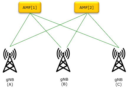
In a 5G network, a gNB (gNodeB) can be connected to multiple Access and Mobility Management Functions (AMF). The selection of which AMF to communicate with for each traffic flow is based on several factors.
-
AMF Selection by the gNB: -
The gNB itself may select the appropriate AMF based on certain parameters when a UE (User Equipment) initiates a connection. The process follows this general flow:
-
AMF Identifier: The gNB receives a list of AMF addresses from the Network Repository Function (NRF). This list includes AMFs that can serve the UE based on the UE’s location (Tracking Area) and network slice requirements.
-
UE-Specific Information: The gNB may consider UE-specific information, such as the Network Slice Selection Assistance Information (NSSAI), priority level, and capability of the AMF to handle specific types of services (e.g., IoT, URLLC, eMBB).
-
Load Balancing: If multiple AMFs are capable of serving the UE, the gNB may implement load balancing techniques, choosing an AMF based on current network load or predefined policies. ==> gNB may not able to do sophisticated load balancing for AMF since it does not have detailed information about how much load is being applied for each of AMF it is connected, but there is a signaling mechanism by which AMF can notify via NGAP message when it is overloaded (refer to this)
-
AMF Selection by the UE: -
In some scenarios, the UE may have a role in determining the AMF, especially during initial registration or handover, by providing specific information to the gNB, such as its supported NSSAI and PLMN (Public Land Mobile Network) preferences.
-
AMF Selection Assisted by the NRF: -
The gNB queries the Network Repository Function (NRF) to discover available AMFs, considering:
-
Network Slicing: The NRF helps find AMFs that match the required network slices (based on NSSAI). For example, a UE requiring a slice for URLLC will be directed to an AMF that supports that service.
-
AMF Pooling: If there are multiple AMFs available in a pool, the gNB and NRF may use load distribution policies to ensure efficient use of network resources.
-
Dynamic AMF Selection for Mobility: -
For ongoing sessions, if the UE moves between different tracking areas, the gNB may decide to communicate with a new AMF, triggering a mobility registration update. The gNB can perform AMF reselection based on the new location or network conditions of the UE.
-
Redundancy and Failover: -
In case of an AMF failure or overload, the gNB can switch to another AMF to maintain service continuity. This ensures high availability and robustness in the 5G core network.
In this situation how each of gNB can figure out(select) which AMF for a specific transaction ?
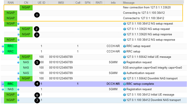
Example 01 : UE inform/specify AMF
When a UE (User Equipment) specifies an AMF (Access and Mobility Management Function) in the RRC Connection Complete message, it typically indicates that the UE has a prior association with this AMF. This scenario usually occurs when the UE is re-registering or reconnecting to the network after a disconnection or mobility event.
The gNB usually attempts to connect to the AMF specified by the UE if it is a valid option based on availability, policies, and location. However, if the AMF is not suitable or unavailable, the gNB will select a different AMF based on its internal selection logic, load balancing, and NRF recommendations. This approach ensures optimal network performance and continuity of service for the UE.
Here’s what the gNB (gNodeB) typically does in this situation:
-
Reception of AMF Information in RRC Connection Complete -
The AMF information is included by the UE in the RRC Connection Complete message as part of the NAS PDU. This AMF information is encapsulated in the GUAMI (Globally Unique AMF Identifier) field, which includes:
-
PLMN ID (Public Land Mobile Network ID): Identifies the home network.
-
AMF Region ID: Identifies a specific region.
-
AMF Set ID: Identifies a set of AMFs within a region.
-
AMF Pointer: Identifies a specific AMF within the set.
-
Verification of the Provided AMF Information -
The gNB checks the provided AMF information to determine if:
-
The specified AMF is reachable.
-
The specified AMF is appropriate for the UE's current location (based on Tracking Area or TAI).
-
The specified AMF matches the network slice requirements indicated by the UE in the NSSAI (Network Slice Selection Assistance Information).
-
AMF Selection Decision Process by the gNB -
The gNB follows a decision-making process to either accept or override the AMF suggested by the UE:
-
If the specified AMF is valid and available:
-
The gNB will forward the NAS signaling to the specified AMF and establish a connection with it.
-
If the specified AMF is not valid, unavailable, or does not match policies:
-
The gNB will query the Network Repository Function (NRF) to discover an appropriate AMF.
-
The gNB may select a different AMF that better suits the UE’s location, slice requirements, or load conditions.
-
Interaction with the AMF -
Once the gNB has decided on an AMF (either the one specified by the UE or a different one), it initiates the N2 interface signaling procedures with that AMF:
-
N2 Initial UE Message: The gNB sends the Initial UE Message over the N2 interface to the selected AMF. This message includes the NAS PDU (which contains the UE’s registration request) and other context information.
-
AMF Context Handling:
-
If the specified AMF is selected, and it recognizes the UE’s context (i.e., the UE was registered with this AMF previously), the AMF can quickly reestablish the UE’s session.
-
If a new AMF is selected, it may need to retrieve the UE’s context from the previous AMF or start a fresh registration process.
-
Handling Context Information and Registration Updates -
If the gNB has selected a different AMF than the one specified by the UE:
-
The new AMF may need to perform context retrieval from the previously specified AMF to ensure a seamless UE experience, depending on whether this is a re-registration or fresh registration.
-
If the context is successfully transferred, the new AMF updates its UE context accordingly.
-
Outcomes and Next Steps -
After completing the AMF selection and registration process:
-
The gNB continues to forward RRC and NAS messages between the UE and the selected AMF.
-
The UE treats the selected AMF as its serving AMF, regardless of whether it was the same AMF initially specified in the RRC Connection Complete message.
{
  message c1: rrcSetupComplete: {
    rrc-TransactionIdentifier 0,
    criticalExtensions rrcSetupComplete: {
      selectedPLMN-Identity 1,
      registeredAMF {
        amf-Identifier '800101'H
      },
      guami-Type native,
      dedicatedNAS-Message '7E014295C6102E7E004169000BF200F...'H
    }
  }
}
Protocol discriminator = 0x7e (5GS Mobility Management)
Security header = 0x1 (Integrity protected)
Auth code = 0x4295c610
Sequence number = 0x2e
Protocol discriminator = 0x7e (5GS Mobility Management)
Security header = 0x0 (Plain 5GS NAS message, not security protected)
Message type = 0x41 (Registration request)
5GS registration type:
  Follow-on request bit = 1
  Value = 1 (initial registration)
ngKSI:
  TSC = 0
  NAS key set identifier = 6
5GS mobile identity:
  5G-GUTI
    MCC = 001
    MNC = 01
    AMF Region ID = 128
    AMF Set ID = 4
    AMF Pointer = 1
    5G-TMSI = 0x32efe46b
UE security capability:
  0xf0 (5G-EA0=1, 128-5G-EA1=1, 128-5G-EA2=1, 128-5G-EA3=1, 5G-EA4=0, 5G-EA5=0, 5G-EA6=0, 5G-EA7=0)
  0x70 (5G-IA0=0, 128-5G-IA1=1, 128-5G-IA2=1, 128-5G-IA3=1, 5G-IA4=0, 5G-IA5=0, 5G-IA6=0, 5G-IA7=0)
  0xf0 (EEA0=1, 128-EEA1=1, 128-EEA2=1, 128-EEA3=1, EEA4=0, EEA5=0, EEA6=0, EEA7=0)
  0x70 (EIA0=0, 128-EIA1=1, 128-EIA2=1, 128-EIA3=1, EIA4=0, EIA5=0, EIA6=0, EIA7=0)
NAS message container:
  Protocol discriminator = 0x7e (5GS Mobility Management)
  Security header = 0x0 (Plain 5GS NAS message, not security protected)
  Message type = 0x41 (Registration request)
  5GS registration type:
    Follow-on request bit = 1
    Value = 1 (initial registration)
  ngKSI:
    TSC = 0
    NAS key set identifier = 6
  5GS mobile identity:
    5G-GUTI
      MCC = 001
      MNC = 01
      AMF Region ID = 128
      AMF Set ID = 4
      AMF Pointer = 1
      5G-TMSI = 0x32efe46b
  5GMM capability:
    0x03 (SGC=0, 5G-IPHC-CP CIoT=0, N3 data=0, 5G-CP CIoT=0, RestrictEC=0, LPP=0, HO attach=1, S1 mode=1)
  UE security capability:
    0xf0 (5G-EA0=1, 128-5G-EA1=1, 128-5G-EA2=1, 128-5G-EA3=1, 5G-EA4=0, 5G-EA5=0, 5G-EA6=0, 5G-EA7=0)
    0x70 (5G-IA0=0, 128-5G-IA1=1, 128-5G-IA2=1, 128-5G-IA3=1, 5G-IA4=0, 5G-IA5=0, 5G-IA6=0, 5G-IA7=0)
    0xf0 (EEA0=1, 128-EEA1=1, 128-EEA2=1, 128-EEA3=1, EEA4=0, EEA5=0, EEA6=0, EEA7=0)
    0x70 (EIA0=0, 128-EIA1=1, 128-EIA2=1, 128-EIA3=1, EIA4=0, EIA5=0, EIA6=0, EIA7=0)
  Requested NSSAI:
    S-NSSAI
      Length of S-NSSAI contents = 1 (SST)
      SST = 0x01
  Last visited registered TAI:
    MCC = 001
    MNC = 01
    TAC = 0x000064
  S1 UE network capability:
    0xf0 (EEA0=1, 128-EEA1=1, 128-EEA2=1, 128-EEA3=1, EEA4=0, EEA5=0, EEA6=0, EEA7=0)
    0x70 (EIA0=0, 128-EIA1=1, 128-EIA2=1, 128-EIA3=1, EIA4=0, EIA5=0, EIA6=0, EIA7=0)
    0xc0 (UEA0=1, UEA1=1, UEA2=0, UEA3=0, UEA4=0, UEA5=0, UEA6=0, UEA7=0)
    0x40 (UCS2=0, UIA1=1, UIA2=0, UIA3=0, UIA4=0, UIA5=0, UIA6=0, UIA7=0)
    0x19 (ProSe-dd=0, ProSe=0, H.245-ASH=0, ACC-CSFB=1, LPP=1, LCS=0, 1xSRVCC=0, NF=1)
    0x80 (ePCO=1, HC-CP CIoT=0, ERw/oPDN=0, S1-U data=0, UP CIoT=0, CP CIoT=0, ProSe-relay=0, ProSe-dc=0)
    0xb0 (15 bearers=1, SGC=0, N1mode=1, DCNR=1, CP backoff=0, RestrictEC=0, V2X PC5=0, multipleDRB=0)
  UE's usage setting = 0x01 (Data centric)
  LADN indication:
    Length = 0
    Data =
  Network slicing indication = 0x00 (DCNI=0, NSSCI=0)
  5GS update type = 0x01 (EPS-PNB-CIoT=no additional information, 5GS-PNB-CIoT=no additional information,
      NG-RAN-RCU=0, SMS requested=1)
initiatingMessage: {
  procedureCode id-InitialUEMessage,
  criticality ignore,
  value {
    protocolIEs {
      {
        id id-RAN-UE-NGAP-ID,
        criticality reject,
        value 1
      },
      {
        id id-NAS-PDU,
        criticality reject,
        value '7E014295C6102E7E004169000BF200F1....'H
      },
      {
        id id-UserLocationInformation,
        criticality reject,
        value userLocationInformationNR: {
          nR-CGI {
            pLMNIdentity '00F110'H,
            nRCellIdentity '001234501'H
          },
          tAI {
            pLMNIdentity '00F110'H,
            tAC '000064'H
          }
        }
      },
      {
        id id-RRCEstablishmentCause,
        criticality ignore,
        value mo-Signalling
      },
      {
        id id-UEContextRequest,
        criticality ignore,
        value requested
      }
    }
  }
}
initiatingMessage: {
  procedureCode id-DownlinkNASTransport,
  criticality ignore,
  value {
    protocolIEs {
      {
        id id-AMF-UE-NGAP-ID,
        criticality reject,
        value 100
      },
      {
        id id-RAN-UE-NGAP-ID,
        criticality reject,
        value 1
      },
      {
        id id-NAS-PDU,
        criticality reject,
        value '7E005B01'H
      }
    }
  }
}
Example 02 : UE does not inform/specify AMF
When the UE does not specify an AMF in the RRC Connection Complete message, the gNB takes responsibility for selecting an appropriate AMF using NRF queries, considering location, network slice requirements, AMF capabilities, and network policies. This ensures that the UE is served by the most suitable AMF based on the network’s current conditions and configurations.
When a UE (User Equipment) does not specify an AMF (Access and Mobility Management Function) in the RRC Connection Complete message, it indicates that the UE does not have a preference or prior association with a specific AMF.
This typically happens when the UE is:
-
Connecting to the 5G network for the first time.
-
Re-registering after a long absence where previous AMF contexts have expired.
-
Changing from a different RAT (Radio Access Technology), such as transitioning from LTE to 5G.
-
Reinitializing due to network-initiated procedures, such as handover or inter-AMF relocation.
In this scenario, the gNB (gNodeB) performs the following steps to select an appropriate AMF for the UE:
-
Determining AMF Availability Using NRF Query -
The gNB queries the Network Repository Function (NRF) to retrieve a list of AMFs that are available to serve the UE. The NRF returns a list of AMFs based on the following parameters:
-
UE Location: The AMFs must serve the Tracking Area (TA) where the UE is located.
-
Network Slice Requirements: The NRF considers the Network Slice Selection Assistance Information (NSSAI) provided by the UE, which indicates the types of network slices required for the UE’s services (e.g., eMBB, URLLC, or IoT).
-
AMF Capabilities: The NRF ensures that only AMFs capable of handling the specified services and functionalities are included in the response.
Selecting an AMF from the Available List -
The gNB selects an appropriate AMF from the list provided by the NRF based on various criteria:
-
AMF Load and Capacity: The gNB may consider the load status of each AMF to distribute the traffic evenly and avoid overloading a particular AMF.
-
AMF Availability: The gNB will ensure that the AMF is available and operational to serve the UE’s requests.
-
AMF Preferences and Network Policies: Network operators can define policies for AMF selection, such as prioritizing certain AMFs for specific services or geographic regions.
-
The selection can also be influenced by predefined policies in the network, such as:
-
Preferred AMF List: The gNB may have a pre-configured list of preferred AMFs.
-
Fallback Mechanisms: If no suitable AMF is available, fallback mechanisms can be used to select a default AMF.
Initiating Registration Request to the Selected AMF -
Once the gNB has selected an AMF, it sends the N2 Initial UE Message to the chosen AMF. This message contains:
-
The NAS PDU received from the UE in the RRC Connection Complete message, which includes the initial registration request.
-
The UE Context Information, such as the UE’s capability, location, and NSSAI.
-
The AMF processes this registration request and establishes a context for the UE, initiating the NAS procedures like authentication and registration.
Handling of NAS Registration and Authentication -
After sending the registration request to the selected AMF:
-
The AMF will respond with the necessary NAS procedures to register the UE, authenticate it, and establish a signaling connection.
-
The gNB acts as a relay between the UE and the AMF, forwarding NAS signaling messages back and forth.
Completing the Registration and Context Establishment -
Once the AMF has authenticated and registered the UE:
-
The gNB and AMF establish a stable signaling connection over the N2 interface.
-
The gNB now knows which AMF is serving this UE and will continue to communicate with it for subsequent NAS signaling and mobility management procedures.
Additional Considerations -
If the UE does not specify an AMF and the gNB cannot find a suitable AMF:
-
The gNB may reject the registration attempt, and the UE might need to retry with different parameters.
-
The gNB may send a redirection message to the UE, instructing it to connect to a different cell or tracking area if no AMF is available for the current location.
{
  message c1: rrcSetupComplete: {
    rrc-TransactionIdentifier 0,
    criticalExtensions rrcSetupComplete: {
      selectedPLMN-Identity 1,
      dedicatedNAS-Message '7E004179000D0100F110F0FF000010325476982E02E0E0'H,
      nonCriticalExtension {
        nonCriticalExtension {
          ul-RRC-Segmentation-r16 true
        }
      }
    }
  }
}
Protocol discriminator = 0x7e (5GS Mobility Management)
Security header = 0x0 (Plain 5GS NAS message, not security protected)
Message type = 0x41 (Registration request)
5GS registration type:
  Follow-on request bit = 1
  Value = 1 (initial registration)
ngKSI:
  TSC = 0
  NAS key set identifier = 7
5GS mobile identity:
  SUCI
    SUPI format = 0 (IMSI)
    MCC = 001
    MNC = 01
    Routing indicator = 0
    Protection sheme id = 0 (Null scheme)
    Home network public key identifier = 0
    MSIN = 0123456789
UE security capability:
  0xe0 (5G-EA0=1, 128-5G-EA1=1, 128-5G-EA2=1, 128-5G-EA3=0, 5G-EA4=0, 5G-EA5=0, 5G-EA6=0, 5G-EA7=0)
  0xe0 (5G-IA0=1, 128-5G-IA1=1, 128-5G-IA2=1, 128-5G-IA3=0, 5G-IA4=0, 5G-IA5=0, 5G-IA6=0, 5G-IA7=0)
initiatingMessage: {
  procedureCode id-InitialUEMessage,
  criticality ignore,
  value {
    protocolIEs {
      {
        id id-RAN-UE-NGAP-ID,
        criticality reject,
        value 1
      },
      {
        id id-NAS-PDU,
        criticality reject,
        value '7E004179000D0100F110F0FF000010325476982E02E0E0'H
      },
      {
        id id-UserLocationInformation,
        criticality reject,
        value userLocationInformationNR: {
          nR-CGI {
            pLMNIdentity '00F110'H,
            nRCellIdentity '001234501'H
          },
          tAI {
            pLMNIdentity '00F110'H,
            tAC '000064'H
          }
        }
      },
      {
        id id-RRCEstablishmentCause,
        criticality ignore,
        value mo-Signalling
      },
      {
        id id-UEContextRequest,
        criticality ignore,
        value requested
      }
    }
  }
}
initiatingMessage: {
  procedureCode id-DownlinkNASTransport,
  criticality ignore,
  value {
    protocolIEs {
      {
        id id-AMF-UE-NGAP-ID,
        criticality reject,
        value 100
      },
      {
        id id-RAN-UE-NGAP-ID,
        criticality reject,
        value 1
      },
      {
        id id-NAS-PDU,
        criticality reject,
        value '7E005600020000213C985803AD3165...'H
      }
    }
  }
}
Reference
- AMF Overview - Cisco
- Exploring the 3GPP AMF Access & Mobility Management Function
- 5G StandAlone Access - Registration Procedure - Part2(AMF selection procedures, slices).
- Overload Control for N2 and NAS - Cisco
- Relative Capacity Configuration Update - Cisco
- 3GPP TS 24.501 v20.1.0 - N1 5GS NAS message procedures
- 3GPP TS 38.413 v19.4.0 - N2 NGAP procedures
- 3GPP TS 29.503 v20.1.0 - Nudm_UECM and Nudm_SDM APIs
- 3GPP TS 29.502 v20.1.0 - Nsmf_PDUSession API
- 3GPP TS 29.518 v20.1.0 - Namf_Communication API
- 3GPP TS 29.509 v20.0.0 - Nausf_UEAuthentication API
- 3GPP TS 29.507 v20.1.0 - Npcf_AMPolicyControl API
- 3GPP TS 29.540 v20.1.0 - Nsmsf_SMService API
- 3GPP TS 29.531 v20.0.0 - Nnssf_NSSelection API
YouTube
- Access Mobility Function (AMF) in 5G - Telco Bytes (2021)