When a data is transferred from Radio Stack(eNB) to Core Network it goes through various Interfaces as illustrated in Figure 1 of Network Architecture and Interface page. When the data go through these interface, they get encapsulated by various tunnel protocol as in Figure 2 of Network Architecture and Interface page. GTP is a specific type of tunneling protocol by which U-plane data (user data) go through as illustrated below. In 3GPP, GTP is specified in 29.281.
If you strip away the acronym, GTP is doing something very ordinary. It puts one IP packet inside another one, and writes a number on the outside. The far end reads that number to know which of its thousands of subscribers the packet belongs to. That number is the
The reason a tunnel is needed at all is worth a sentence. A UE keeps its IP address while it moves across the network, and that address means nothing to the routers in between. So the packet gets wrapped in a second IP header that the transport network does understand, carried to the far end, and unwrapped. The inner address never has to be routable anywhere except at the two ends.
The name still says GPRS, which dates it. GTP arrived with 2.5G and has survived every generation since, largely unchanged in shape. The version in 5G is the same protocol carrying the same header that it did twenty years ago, with one extension header added for QoS.
- Where GTP Sits in the Network
- GTP-C, GTP-U and GTP Prime
- GTP-U Header
- TEID : the Number That Makes a Tunnel
- Signaling for GTP setup
- Reading a Real GTP-U Header
- Examples
Where GTP Sits in the Network
The figure below draws a protocol stack across the whole path, UE on the left, server on the right. The red boxes are the ones to look at. They appear only in the middle, on the eNB, the SGW and the PGW, and never at either end.

That absence is the point of the whole picture. The UE has no GTP in its stack. Neither does the server. Both are exchanging ordinary IP packets, and neither knows a tunnel exists. Which is exactly what a transport network is supposed to look like from the outside.
Follow the red boxes and you can see there are two separate tunnels here, not one. The first runs from eNB to SGW over S1-U. The second runs from SGW to PGW over S5/S8. A packet is decapsulated and re-encapsulated in the middle, with a different TEID on each side.
Notice also what is underneath every red box. UDP, then IP. GTP is not its own IP protocol number the way SCTP is. It is an application riding on UDP, on port 2152, which is one reason it travels through ordinary networks so easily.
GTP-C, GTP-U and GTP Prime
Something worth clearing up before the header, because the same four letters get used for three different protocols. I have sat in more than one meeting where two people meant different things by GTP for a quarter of an hour before anyone noticed.
Name |
UDP port |
What it carries |
Where you meet it |
2152 |
User data |
S1-U, S5/S8 and N3. This is the one this page is about, and the one specified in 29.281. |
|
GTP-C |
2123 |
Signalling that builds tunnels |
S11, S5/S8 and S10 in EPC, specified in 29.274. In a 5G core it has largely been replaced by PFCP on N4 and by the service based interfaces. That is why it barely appears in the capture on this page. |
GTP' |
3386 |
Charging records |
Between charging nodes. You will almost certainly never see it. It is still why there is a Protocol Type bit in the header, and why that bit is set to 1 in everything else. |
The distinction that actually matters day to day is the first two. GTP-U moves the traffic and GTP-C used to be what set it up. In 5G that second job moved elsewhere. What you will see in the signalling section below is NGAP and PFCP arranging a tunnel that GTP-U will then carry. GTP itself has no way to set anything up.
GTP-U Header
The header is short, and most of the time it is exactly eight bytes. The complication is that three flag bits can each add fields, and the rule for when those fields are present is not quite what you would guess.
Following is the GTP Header format. User Data (usually IP data) is encapsulated by a GTP packet following this header as shown in example section.
< 3GPP 29.281 - Figure 5.1-1: Outline of the GTP-U Header >

Read that figure with the footnotes in mind, because the optional part at the bottom does not behave the way the arrows suggest at first glance.
Octet |
Field |
Notes |
1 |
Version (bits 8-6) |
001 for GTPv1, which is what everything on this page is. GTPv2 exists but only for GTP-C. |
PT, Protocol Type (bit 5) |
1 means GTP, 0 means GTP prime. In practice this bit is always 1. |
|
(*) spare (bit 4) |
Set to 0. |
|
An extension header follows. This is the bit 5G sets, because QFI travels in one. |
||
The sequence number field is meaningful. |
||
The N-PDU number field is meaningful. |
||
2 |
Message Type |
255 for ordinary user data. The full list is short and worth knowing, see below. |
3 - 4 |
Length |
Everything after octet 8, so the optional fields and any extension headers count towards it. It is not the length of the whole packet and it is not the length of the payload alone. |
5 - 8 |
The whole reason the protocol exists. Its own section is below. |
|
9 - 10 |
Sequence Number |
These three fields are the trap. They are present, and take up their four bytes, if |
11 |
N-PDU Number |
|
12 |
Next Extension Header Type |
So a plain GTP-U packet with no flags set has a twelve byte header, and one carrying a QFI has sixteen. Both of the real packets at the end of this page are the sixteen byte kind.
The message type list is short enough to be worth reading in full. Four of the six exist purely to keep a tunnel healthy, and only one carries any user data at all.
Type |
Message |
What it is |
1 |
Echo Request |
Path keepalive between two GTP-U endpoints. Nothing to do with any particular tunnel, which is why these carry TEID zero. |
2 |
Echo Response |
|
26 |
Error Indication |
A packet arrived for a TEID the receiver knows nothing about. Worth taking seriously in a live network, since it usually means one end tore a session down and the other did not notice. |
31 |
Supported Extension Headers Notification |
Sent when an extension header arrives that the receiver does not understand. |
254 |
End Marker |
During a handover, this is the last thing sent down the old path. It tells the target that nothing more is coming, so it can stop waiting and start delivering. |
User data. In any real capture this is essentially all of the traffic, and it is what both GTP-U frames near the end of this page are. |
TEID : the Number That Makes a Tunnel
Four bytes, and they carry the whole idea. When a packet arrives at a UPF over N3, nothing in the inner IP header tells it which subscriber this is. The inner address is a private one, handed out by the core, and thousands of UEs might be using the same range. The TEID is what makes the packet identifiable.
Who chooses the number is the part that trips people up, and I had it backwards for years, so let me be blunt about it.
Which means there is no such thing as the TEID of a session. There are two of them, one per direction, chosen independently by different nodes, and they never match.
Both of these numbers appear in the signalling below, and both then appear again on real user plane packets at the end of the page. Follow one of them from the message that allocated it to the packet that used it. That is the most useful thing you can do with this capture, and the last section does exactly that.
Signaling for GTP setup
Signaling for GTP setup does not rely on GTP itself, since the protocol does not include any inherent procedures for handshaking or session establishment. Instead, the setup of GTP tunnels depends on signaling exchanges between various core network elements such as the MME/AMF, SGW/UPF, and PGW/SMF. These signaling procedures ensure that resources are allocated, tunnel identifiers are assigned, and the necessary context information is distributed across the involved nodes. In practice, control-plane signaling protocols like S1-AP, NGAP, and GTP-C carry the coordination messages that instruct network elements to create or release GTP tunnels for user-plane traffic. As a result, while GTP itself functions simply as a tunneling mechanism, its successful operation relies heavily on surrounding signaling frameworks that orchestrate the tunnel configuration and maintain consistency across the network.
Following is an overall signaling procedure to setup GTP pipes in 5G/NR network. The process begins with the UE initiating a PDU session establishment request, which is handled by the AMF and then forwarded to the SMF for session management. Once the session is accepted, the AMF triggers the PDU Session Resource Setup Request toward the gNB, carrying the uplink TEID information allocated by the UPF. The gNB responds with the PDU Session Resource Setup Response, delivering the downlink TEID to complete the mapping. With both TEIDs exchanged, the network can now encapsulate and route user data packets using GTP-U in both uplink and downlink directions. This sequence highlights that GTP setup is the result of higher-layer signaling coordination, ensuring the correct assignment of resources and identifiers before actual GTP packet transmission begins.
Two green dashed arrows in the figure below carry the whole story. One brings a TEID from the UPF to the gNB, the other takes a different TEID from the gNB back to the UPF. Everything before them is arranging that exchange, and everything after them is user data.
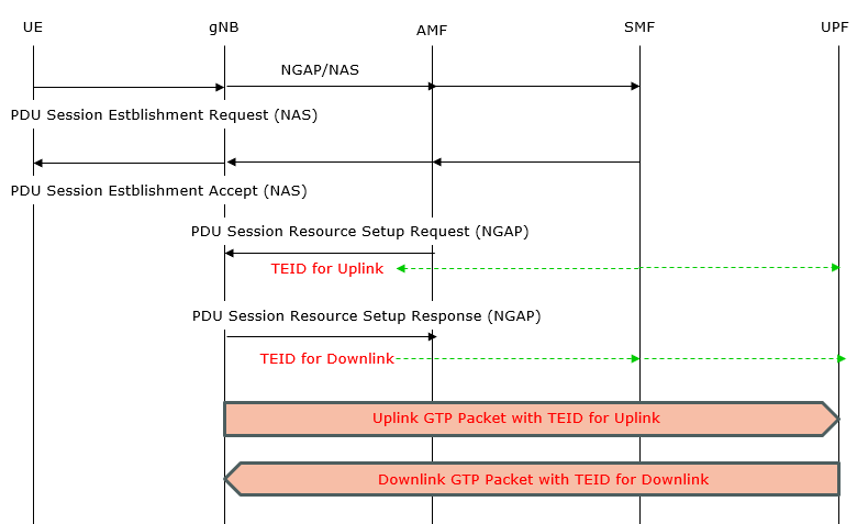
Notice which way each green arrow points, and compare it with the direction of the shaded bar underneath it. The TEID for uplink travels downward, from the UPF towards the gNB, and is then used on packets travelling the other way. That inversion is not a mistake in the drawing. It is the receiver telling the sender what number to write.
UE → gNB → AMF: The UE sends a PDU Session Establishment Request (NAS/5GSM). The gNB forwards it over NGAP to the AMF.AMF → SMF (SMF ↔ UPF): The AMF requests session creation from the SMF. The SMF selects/programs a UPF via N4/PFCP (Session Establishment/Modification). The UPF allocates an uplink TEID and returns its GTP-U endpoint (IP + TEID).AMF → UE (via gNB): The AMF sends PDU Session Establishment Accept (NAS) to confirm session parameters (e.g., DNN, SSC mode, QoS), proceeding in parallel with user-plane setup.AMF → gNB (NGAP): The AMF delivers PDU Session Resource Setup Request containing UP Transport Layer Information with the UPF IP and the UL TEID. This tells the gNB how to encapsulate uplink user traffic in GTP-U.gNB → AMF (NGAP): After creating radio bearers and its local GTP-U endpoint, the gNB replies with PDU Session Resource Setup Response, providing the gNB’s GTP-U IP and the downlink TEID to be used by the UPF.AMF/SMF → UPF (PFCP update): The SMF updates the UPF’s PDR/FAR/QER with the gNB’s DL endpoint (IP + TEID), enabling correct downlink tunneling.User plane starts: - Uplink: The gNB encapsulates UE packets with the UL TEID and sends them to the UPF.
- Downlink: The UPF encapsulates packets with the DL TEID and sends them to the gNB, which delivers them to the UE.
Following is an example log snippet from Amarisoft showing the details of this signaling process described above. This is the combined log of Amarisoft gNB and MME
The numbers down the middle of the screenshot are the ones used to label the dumps below, so it is worth a moment before reading on. The RAN and CN columns show which side each message belongs to, and the last two rows change colour because they are the first user plane packets. Everything above them is still setup.
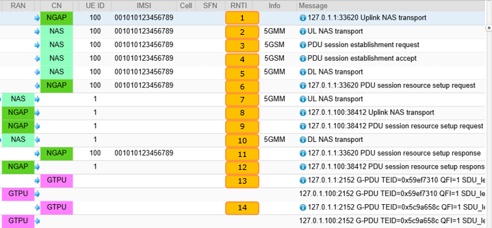
Two details in that list are easy to miss. Frames 13 and 14 already carry the TEIDs in the Info column, so you can read them off the summary without opening anything. And the dumps below cover frames 1 to 8 plus 11, 13 and 14, so a few of the numbered rows have no dump of their own.
In terms of message hierarchy, NGAP are main message carrier between gNB and Core network. NAS messages are embedded into NGAP messages to shuttle back and forth between gNB and Core network.
For example, an Uplink NAS transport (1) carries UL NAS transport and PDU session establishment request embedded in it. In other words, the NAS message UL NAS transport(2) is extracted from the Uplink NAS transport(1) by 5GMM and PDU session establishment request(3) is extracted from the UL NAS transport(2) by 5GSM.
The UE has sent something over the air that the gNB is not allowed to read. So the gNB wraps it in NGAP and forwards it, and Uplink NAS Transport is the envelope for exactly that. In the protocolIEs list you will find id-NAS-PDU carrying an opaque hex string, next to the two identifiers that say whose it is.
Message: 127.0.1.1:33620 Uplink NAS transport

Data:
0000:  00 2e 40 80 af 00 00 04  00 0a 00 02 00 64 00 55  ..@..........d.U
0010:  00 02 00 01 00 26 00 80  88 80 86 7e 02 39 57 26  .....&.....~.9W&
0020:  98 03 7e 00 67 01 00 6b  2e 01 55 c1 00 00 93 28  ..~.g..k..U....(
0030:  01 00 7b 00 5e 80 c2 23  16 01 00 00 16 10 8c bb  ..{.^..#........
0040:  1d 1d 8c bb 1d 1d 8c bb  1d 1d 8c bb 1d 1d 2a c2  ..............*.
0050:  23 16 02 00 00 16 10 c6  00 c0 d1 3b de b9 d7 0b  #..........;....
0060:  68 d9 33 26 ec fe fb 2a  80 21 10 01 00 00 10 81  h.3&...*.!......
0070:  06 00 00 00 00 83 06 00  00 00 00 00 0d 00 00 03  ................
0080:  00 00 0a 00 00 05 00 00  10 00 00 11 00 00 23 00  ..............#.
0090:  00 24 00 12 01 81 25 09  08 69 6e 74 65 72 6e 65  .$....%..interne
00a0:  74 00 79 40 0f 40 00 f1  10 00 12 34 50 10 00 f1  t.y@.@.....4P...
00b0:  10 00 00 64                                       ...d
initiatingMessage: {
  procedureCode id-UplinkNASTransport,
  criticality ignore,
  value {
    protocolIEs {
      {
        id id-AMF-UE-NGAP-ID,
        criticality reject,
        value 100
      },
      {
        id id-RAN-UE-NGAP-ID,
        criticality reject,
        value 1
      },
      {
        id id-NAS-PDU,
        criticality reject,
        value '7E0239572698037E00....74'H
      },
      {
        id id-UserLocationInformation,
        criticality ignore,
        value userLocationInformationNR: {
          nR-CGI {
            pLMNIdentity '00F110'H,
            nRCellIdentity '001234501'H
          },
          tAI {
            pLMNIdentity '00F110'H,
            tAC '000064'H
          }
        }
      }
    }
  }
}
The same bytes as that NAS-PDU, now decoded. This is 5GMM, the mobility management layer, and its whole job here is to carry something belonging to a different layer. Payload container type 1 means session management, which is the next envelope down.
Message: UL NAS transport

Data:
0000:  7e 02 39 57 26 98 03 7e  00 67 01 00 6b 2e 01 55  ~.9W&..~.g..k..U
0010:  c1 00 00 93 28 01 00 7b  00 5e 80 c2 23 16 01 00  ....(..{.^..#...
0020:  00 16 10 8c bb 1d 1d 8c  bb 1d 1d 8c bb 1d 1d 8c  ................
0030:  bb 1d 1d 2a c2 23 16 02  00 00 16 10 c6 00 c0 d1  ...*.#..........
0040:  3b de b9 d7 0b 68 d9 33  26 ec fe fb 2a 80 21 10  ;....h.3&...*.!.
0050:  01 00 00 10 81 06 00 00  00 00 83 06 00 00 00 00  ................
0060:  00 0d 00 00 03 00 00 0a  00 00 05 00 00 10 00 00  ................
0070:  11 00 00 23 00 00 24 00  12 01 81 25 09 08 69 6e  ...#..$....%..in
0080:  74 65 72 6e 65 74                                 ternet
Protocol discriminator = 0x7e (5GS Mobility Management)
Security header = 0x2 (Integrity protected and ciphered)
Auth code = 0x39572698
Sequence number = 0x03
Protocol discriminator = 0x7e (5GS Mobility Management)
Security header = 0x0 (Plain 5GS NAS message, not security protected)
Message type = 0x67 (UL NAS transport)
Payload container type = 1 (N1 SM information)
Payload container:
  Protocol discriminator = 0x2e (5GS Session Management)
  PDU session identity = 1
  Procedure transaction identity = 85
  Message type = 0xc1 (PDU session establishment request)
  Integrity protection maximum data data:
    Maximum data rate per UE for user-plane integrity protection for uplink = 0x00 (64 kbps)
    Maximum data rate per UE for user-plane integrity protection for downlink = 0x00 (64 kbps)
  PDU session type = 0x3 (IPv4v6)
  5GSM capability:
    0x00 (TPMIC=0, ATSSS-ST=0, EPT-S1=0, MH6-PDU=0, RqoS=0)
  Extended protocol configuration options:
    Ext = 1
    Configuration protocol = 0
    Protocol ID = 0xc223 (CHAP)
    Data = 01 00 00 16 10 8c bb 1d 1d 8c bb 1d 1d 8c bb 1d 1d 8c bb 1d 1d 2a
    Protocol ID = 0xc223 (CHAP)
    Data = 02 00 00 16 10 c6 00 c0 d1 3b de b9 d7 0b 68 d9 33 26 ec fe fb 2a
    Protocol ID = 0x8021 (IPCP)
    Data = 01 00 00 10 81 06 00 00 00 00 83 06 00 00 00 00
    Protocol ID = 0x000d (DNS Server IPv4 Address Request)
    Data =
    Protocol ID = 0x0003 (DNS Server IPv6 Address Request)
    Data =
    Protocol ID = 0x000a (IP address allocation via NAS signalling)
    Data =
    Protocol ID = 0x0005 (MS Support of Network Requested Bearer Control indicator)
    Data =
    Protocol ID = 0x0010 (IPv4 Link MTU Request)
    Data =
    Protocol ID = 0x0011 (MS support of Local address in TFT indicator)
    Data =
    Protocol ID = 0x0023 (QoS rules with the length of two octets support indicator)
    Data =
    Protocol ID = 0x0024 (QoS flow descriptions with the length of two octets support indicator)
    Data =
PDU session ID = 1
Request type = 0x1 (initial request)
DNN = "internet"
Three envelopes in, and here is what the UE actually wanted. Everything above this was transport for it. The hex will look familiar, because this same message was already sitting inside both of the previous two dumps.
Message: PDU session establishment request

Data:
0000:  2e 01 55 c1 00 00 93 28  01 00 7b 00 5e 80 c2 23  ..U....(..{.^..#
0010:  16 01 00 00 16 10 8c bb  1d 1d 8c bb 1d 1d 8c bb  ................
0020:  1d 1d 8c bb 1d 1d 2a c2  23 16 02 00 00 16 10 c6  ......*.#.......
0030:  00 c0 d1 3b de b9 d7 0b  68 d9 33 26 ec fe fb 2a  ...;....h.3&...*
0040:  80 21 10 01 00 00 10 81  06 00 00 00 00 83 06 00  .!..............
0050:  00 00 00 00 0d 00 00 03  00 00 0a 00 00 05 00 00  ................
0060:  10 00 00 11 00 00 23 00  00 24 00                 ......#..$.
Protocol discriminator = 0x2e (5GS Session Management)
PDU session identity = 1
Procedure transaction identity = 85
Message type = 0xc1 (PDU session establishment request)
Integrity protection maximum data data:
  Maximum data rate per UE for user-plane integrity protection for uplink = 0x00 (64 kbps)
  Maximum data rate per UE for user-plane integrity protection for downlink = 0x00 (64 kbps)
PDU session type = 0x3 (IPv4v6)
5GSM capability:
  0x00 (TPMIC=0, ATSSS-ST=0, EPT-S1=0, MH6-PDU=0, RqoS=0)
Extended protocol configuration options:
  Ext = 1
  Configuration protocol = 0
  Protocol ID = 0xc223 (CHAP)
  Data = 01 00 00 16 10 8c bb 1d 1d 8c bb 1d 1d 8c bb 1d 1d 8c bb 1d 1d 2a
  Protocol ID = 0xc223 (CHAP)
  Data = 02 00 00 16 10 c6 00 c0 d1 3b de b9 d7 0b 68 d9 33 26 ec fe fb 2a
  Protocol ID = 0x8021 (IPCP)
  Data = 01 00 00 10 81 06 00 00 00 00 83 06 00 00 00 00
  Protocol ID = 0x000d (DNS Server IPv4 Address Request)
  Data =
  Protocol ID = 0x0003 (DNS Server IPv6 Address Request)
  Data =
  Protocol ID = 0x000a (IP address allocation via NAS signalling)
  Data =
  Protocol ID = 0x0005 (MS Support of Network Requested Bearer Control indicator)
  Data =
  Protocol ID = 0x0010 (IPv4 Link MTU Request)
  Data =
  Protocol ID = 0x0011 (MS support of Local address in TFT indicator)
  Data =
  Protocol ID = 0x0023 (QoS rules with the length of two octets support indicator)
  Data =
  Protocol ID = 0x0024 (QoS flow descriptions with the length of two octets support indicator)
  Data =
The answer. Selected PDU session type IPv4, a set of authorised QoS rules, and a PDU address, which is the IP address the UE will use from now on. At this point the UE has a session on paper. It still has no tunnel to send anything through.
Message: PDU session establishment accept

Data:
0000:  2e 01 55 c2 11 00 09 01  00 06 31 3f 01 01 ff 01  ..U.......1?....
0010:  06 04 b7 1b 03 f4 24 59  32 29 05 01 c0 a8 03 02  ......$Y2)......
0020:  22 01 01 75 00 0f 50 00  0c 52 01 01 09 04 06 fe  "..u..P..R......
0030:  fe fa fa 0a 02 79 00 09  01 20 42 01 01 09 07 01  .....y... B.....
0040:  50 7b 00 15 80 80 21 0a  03 00 00 0a 81 06 08 08  P{....!.........
0050:  08 08 00 0d 04 08 08 08  08 25 1c 08 69 6e 74 65  .........%..inte
0060:  72 6e 65 74 06 6d 6e 63  30 30 31 06 6d 63 63 30  rnet.mnc001.mcc0
0070:  30 31 04 67 70 72 73                              01.gprs
Protocol discriminator = 0x2e (5GS Session Management)
PDU session identity = 1
Procedure transaction identity = 85
Message type = 0xc2 (PDU session establishment accept)
Selected PDU session type = 0x1 (IPv4)
Selected SSC mode = 0x1 (1)
Authorized QoS rules:
  QoS rule 1:
    QoS rule identifier = 1
    Rule operation code = 1 (create new QoS rule)
    DQR = 1 (the QoS rule is the default QoS rule)
    Number of packet filters = 1
    Packet filter identifier = 15
      Packet filter direction = 3 (bidirectional)
      Match-all
    QoS rule precedence = 255
    QFI = 1
Session AMBR:
  Session-AMBR for downlink = 3000000 kbps
  Session-AMBR for uplink = 1000000 kbps
5GSM cause = 0x32 (PDU session type IPv4 only allowed)
PDU address:
  SI6LLA = 0
  PDU session type = 1 (IPv4)
  IPv4 = 192.168.3.2
S-NSSAI:
  Length of S-NSSAI contents = 1 (SST)
  SST = 0x01
Mapped EPS bearer contexts:
  Mapped EPS bearer context 1:
    EPS bearer identity = 5
    Operation code = 1 (create new EPS bearer)
    E = 1 (parameters list is included)
    Number of EPS parameters = 2
    Mapped EPS QoS parameters:
      QCI = 9
    APN-AMBR:
      APN-AMBR for downlink = 2816000000 bits
      APN-AMBR for uplink = 768000000 bits
Authorized QoS flow descriptions:
  QoS flow description 1:
    QFI = 1
    Operation code = 1 (create new QoS flow description)
    E = 1 (parameters list is included)
    Number of parameters = 2
    5QI = 9
    EPS bearer identity = 5
Extended protocol configuration options:
  Ext = 1
  Configuration protocol = 0
  Protocol ID = 0x8021 (IPCP)
  Data = 03 00 00 0a 81 06 08 08 08 08
  Protocol ID = 0x000d (DNS Server IPv4 Address)
  Data = 8.8.8.8
DNN = "internet.mnc001.mcc001.gprs"
The accept from the previous dump, wrapped for the trip back. Same relationship that (2) had with (3), just pointing the other way.
Message: DL NAS transport

Data:
0000:  7e 02 75 b7 5e 84 04 7e  00 68 01 00 77 2e 01 55  ~.u.^..~.h..w..U
0010:  c2 11 00 09 01 00 06 31  3f 01 01 ff 01 06 04 b7  .......1?.......
0020:  1b 03 f4 24 59 32 29 05  01 c0 a8 03 02 22 01 01  ...$Y2)......"..
0030:  75 00 0f 50 00 0c 52 01  01 09 04 06 fe fe fa fa  u..P..R.........
0040:  0a 02 79 00 09 01 20 42  01 01 09 07 01 50 7b 00  ..y... B.....P{.
0050:  15 80 80 21 0a 03 00 00  0a 81 06 08 08 08 08 00  ...!............
0060:  0d 04 08 08 08 08 25 1c  08 69 6e 74 65 72 6e 65  ......%..interne
0070:  74 06 6d 6e 63 30 30 31  06 6d 63 63 30 30 31 04  t.mnc001.mcc001.
0080:  67 70 72 73 12 01                                 gprs..
Protocol discriminator = 0x7e (5GS Mobility Management)
Security header = 0x2 (Integrity protected and ciphered)
Auth code = 0x75b75e84
Sequence number = 0x04
Protocol discriminator = 0x7e (5GS Mobility Management)
Security header = 0x0 (Plain 5GS NAS message, not security protected)
Message type = 0x68 (DL NAS transport)
Payload container type = 1 (N1 SM information)
Payload container:
  Protocol discriminator = 0x2e (5GS Session Management)
  PDU session identity = 1
  Procedure transaction identity = 85
  Message type = 0xc2 (PDU session establishment accept)
  Selected PDU session type = 0x1 (IPv4)
  Selected SSC mode = 0x1 (1)
  Authorized QoS rules:
    QoS rule 1:
      QoS rule identifier = 1
      Rule operation code = 1 (create new QoS rule)
      DQR = 1 (the QoS rule is the default QoS rule)
      Number of packet filters = 1
      Packet filter identifier = 15
        Packet filter direction = 3 (bidirectional)
        Match-all
      QoS rule precedence = 255
      QFI = 1
  Session AMBR:
    Session-AMBR for downlink = 3000000 kbps
    Session-AMBR for uplink = 1000000 kbps
  5GSM cause = 0x32 (PDU session type IPv4 only allowed)
  PDU address:
    SI6LLA = 0
    PDU session type = 1 (IPv4)
    IPv4 = 192.168.3.2
  S-NSSAI:
    Length of S-NSSAI contents = 1 (SST)
    SST = 0x01
  Mapped EPS bearer contexts:
    Mapped EPS bearer context 1:
      EPS bearer identity = 5
      Operation code = 1 (create new EPS bearer)
      E = 1 (parameters list is included)
      Number of EPS parameters = 2
      Mapped EPS QoS parameters:
        QCI = 9
      APN-AMBR:
        APN-AMBR for downlink = 2816000000 bits
        APN-AMBR for uplink = 768000000 bits
  Authorized QoS flow descriptions:
    QoS flow description 1:
      QFI = 1
      Operation code = 1 (create new QoS flow description)
      E = 1 (parameters list is included)
      Number of parameters = 2
      5QI = 9
      EPS bearer identity = 5
  Extended protocol configuration options:
    Ext = 1
    Configuration protocol = 0
    Protocol ID = 0x8021 (IPCP)
    Data = 03 00 00 0a 81 06 08 08 08 08
    Protocol ID = 0x000d (DNS Server IPv4 Address)
    Data = 8.8.8.8
  DNN = "internet.mnc001.mcc001.gprs"
PDU session ID = 1
This is the one that matters for GTP. Everything before it arranged the session. This message hands over a tunnel endpoint. Look for transportLayerAddress and gTP-TEID together near the bottom. Between them they tell the gNB where to send uplink data and what number to stamp on it.
Message: 127.0.1.1:33620 PDU session resource setup request

Data:
0000:  00 1d 00 80 df 00 00 04  00 0a 00 02 00 64 00 55  .............d.U
0010:  00 02 00 01 00 4a 00 80  bd 00 40 01 80 86 7e 02  .....J....@...~.
0020:  75 b7 5e 84 04 7e 00 68  01 00 77 2e 01 55 c2 11  u.^..~.h..w..U..
0030:  00 09 01 00 06 31 3f 01  01 ff 01 06 04 b7 1b 03  .....1?.........
0040:  f4 24 59 32 29 05 01 c0  a8 03 02 22 01 01 75 00  .$Y2)......"..u.
0050:  0f 50 00 0c 52 01 01 09  04 06 fe fe fa fa 0a 02  .P..R...........
0060:  79 00 09 01 20 42 01 01  09 07 01 50 7b 00 15 80  y... B.....P{...
0070:  80 21 0a 03 00 00 0a 81  06 08 08 08 08 00 0d 04  .!..............
0080:  08 08 08 08 25 1c 08 69  6e 74 65 72 6e 65 74 06  ....%..internet.
0090:  6d 6e 63 30 30 31 06 6d  63 63 30 30 31 04 67 70  mnc001.mcc001.gp
00a0:  72 73 12 01 00 20 2f 00  00 04 00 82 00 0a 0c b2  rs... /.........
00b0:  d0 5e 00 30 3b 9a ca 00  00 8b 00 0a 01 f0 7f 00  .^.0;...........
00c0:  01 64 59 ef 73 10 00 86  00 01 00 00 88 00 07 01  .dY.s...........
00d0:  01 00 00 09 38 0a 00 6e  40 0a 0c b2 d0 5e 00 30  ....8..n@....^.0
00e0:  3b 9a ca 00                                       ;...
initiatingMessage: {
  procedureCode id-PDUSessionResourceSetup,
  criticality reject,
  value {
    protocolIEs {
      {
        id id-AMF-UE-NGAP-ID,
        criticality reject,
        value 100
      },
      {
        id id-RAN-UE-NGAP-ID,
        criticality reject,
        value 1
      },
      {
        id id-PDUSessionResourceSetupListSUReq,
        criticality reject,
        value {
          {
            pDUSessionID 1,
            pDUSessionNAS-PDU '7E0275B75E84047E00680100772...1201'H,
            s-NSSAI {
              sST '01'H
            },
            pDUSessionResourceSetupRequestTransfer {
              protocolIEs {
                {
                  id id-PDUSessionAggregateMaximumBitRate,
                  criticality reject,
                  value {
                    pDUSessionAggregateMaximumBitRateDL 3000000000,
                    pDUSessionAggregateMaximumBitRateUL 1000000000
                  }
                },
                {
                  id id-UL-NGU-UP-TNLInformation,
                  criticality reject,
                  value gTPTunnel: {
                    transportLayerAddress '7F000164'H,
                    gTP-TEID '59EF7310'H
                  }
                },
                {
                  id id-PDUSessionType,
                  criticality reject,
                  value ipv4
                },
                {
                  id id-QosFlowSetupRequestList,
                  criticality reject,
                  value {
                    {
                      qosFlowIdentifier 1,
                      qosFlowLevelQosParameters {
                        qosCharacteristics nonDynamic5QI: {
                          fiveQI 9
                        },
                        allocationAndRetentionPriority {
                          priorityLevelARP 15,
                          pre-emptionCapability shall-not-trigger-pre-emption,
                          pre-emptionVulnerability not-pre-emptable
                        }
                      },
                      e-RAB-ID 5
                    }
                  }
                }
              }
            }
          }
        }
      },
      {
        id id-UEAggregateMaximumBitRate,
        criticality ignore,
        value {
          uEAggregateMaximumBitRateDL 3000000000,
          uEAggregateMaximumBitRateUL 1000000000
        }
      }
    }
  }
}
Byte for byte the same message as (2), which is worth knowing before you go looking for a difference. The capture is the gNB's log and the core's log merged into one, so most messages are recorded twice. Two log entries, one message.
Message: UL NAS transport

Data:
0000:  7e 02 39 57 26 98 03 7e  00 67 01 00 6b 2e 01 55  ~.9W&..~.g..k..U
0010:  c1 00 00 93 28 01 00 7b  00 5e 80 c2 23 16 01 00  ....(..{.^..#...
0020:  00 16 10 8c bb 1d 1d 8c  bb 1d 1d 8c bb 1d 1d 8c  ................
0030:  bb 1d 1d 2a c2 23 16 02  00 00 16 10 c6 00 c0 d1  ...*.#..........
0040:  3b de b9 d7 0b 68 d9 33  26 ec fe fb 2a 80 21 10  ;....h.3&...*.!.
0050:  01 00 00 10 81 06 00 00  00 00 83 06 00 00 00 00  ................
0060:  00 0d 00 00 03 00 00 0a  00 00 05 00 00 10 00 00  ................
0070:  11 00 00 23 00 00 24 00  12 01 81 25 09 08 69 6e  ...#..$....%..in
0080:  74 65 72 6e 65 74                                 ternet
Protocol discriminator = 0x7e (5GS Mobility Management)
Security header = 0x2 (Integrity protected and ciphered)
Auth code = 0x39572698
Sequence number = 0x03
Protocol discriminator = 0x7e (5GS Mobility Management)
Security header = 0x0 (Plain 5GS NAS message, not security protected)
Message type = 0x67 (UL NAS transport)
Payload container type = 1 (N1 SM information)
Payload container:
  Protocol discriminator = 0x2e (5GS Session Management)
  PDU session identity = 1
  Procedure transaction identity = 85
  Message type = 0xc1 (PDU session establishment request)
  Integrity protection maximum data data:
    Maximum data rate per UE for user-plane integrity protection for uplink = 0x00 (64 kbps)
    Maximum data rate per UE for user-plane integrity protection for downlink = 0x00 (64 kbps)
  PDU session type = 0x3 (IPv4v6)
  5GSM capability:
    0x00 (TPMIC=0, ATSSS-ST=0, EPT-S1=0, MH6-PDU=0, RqoS=0)
  Extended protocol configuration options:
    Ext = 1
    Configuration protocol = 0
    Protocol ID = 0xc223 (CHAP)
    Data = 01 00 00 16 10 8c bb 1d 1d 8c bb 1d 1d 8c bb 1d 1d 8c bb 1d 1d 2a
    Protocol ID = 0xc223 (CHAP)
    Data = 02 00 00 16 10 c6 00 c0 d1 3b de b9 d7 0b 68 d9 33 26 ec fe fb 2a
    Protocol ID = 0x8021 (IPCP)
    Data = 01 00 00 10 81 06 00 00 00 00 83 06 00 00 00 00
    Protocol ID = 0x000d (DNS Server IPv4 Address Request)
    Data =
    Protocol ID = 0x0003 (DNS Server IPv6 Address Request)
    Data =
    Protocol ID = 0x000a (IP address allocation via NAS signalling)
    Data =
    Protocol ID = 0x0005 (MS Support of Network Requested Bearer Control indicator)
    Data =
    Protocol ID = 0x0010 (IPv4 Link MTU Request)
    Data =
    Protocol ID = 0x0011 (MS support of Local address in TFT indicator)
    Data =
    Protocol ID = 0x0023 (QoS rules with the length of two octets support indicator)
    Data =
    Protocol ID = 0x0024 (QoS flow descriptions with the length of two octets support indicator)
    Data =
PDU session ID = 1
Request type = 0x1 (initial request)
DNN = "internet"
Likewise identical to (1). The only thing that changed is the endpoint on the Message line, 127.0.1.100:38412 here against 127.0.1.1:33620 there. That is one SCTP association written down from each of its two ends.
Message: 127.0.1.100:38412 Uplink NAS transport

Data:
0000:  00 2e 40 80 af 00 00 04  00 0a 00 02 00 64 00 55  ..@..........d.U
0010:  00 02 00 01 00 26 00 80  88 80 86 7e 02 39 57 26  .....&.....~.9W&
0020:  98 03 7e 00 67 01 00 6b  2e 01 55 c1 00 00 93 28  ..~.g..k..U....(
0030:  01 00 7b 00 5e 80 c2 23  16 01 00 00 16 10 8c bb  ..{.^..#........
0040:  1d 1d 8c bb 1d 1d 8c bb  1d 1d 8c bb 1d 1d 2a c2  ..............*.
0050:  23 16 02 00 00 16 10 c6  00 c0 d1 3b de b9 d7 0b  #..........;....
0060:  68 d9 33 26 ec fe fb 2a  80 21 10 01 00 00 10 81  h.3&...*.!......
0070:  06 00 00 00 00 83 06 00  00 00 00 00 0d 00 00 03  ................
0080:  00 00 0a 00 00 05 00 00  10 00 00 11 00 00 23 00  ..............#.
0090:  00 24 00 12 01 81 25 09  08 69 6e 74 65 72 6e 65  .$....%..interne
00a0:  74 00 79 40 0f 40 00 f1  10 00 12 34 50 10 00 f1  t.y@.@.....4P...
00b0:  10 00 00 64                                       ...d
initiatingMessage: {
  procedureCode id-UplinkNASTransport,
  criticality ignore,
  value {
    protocolIEs {
      {
        id id-AMF-UE-NGAP-ID,
        criticality reject,
        value 100
      },
      {
        id id-RAN-UE-NGAP-ID,
        criticality reject,
        value 1
      },
      {
        id id-NAS-PDU,
        criticality reject,
        value '7E0239572698037E00670...574'H
      },
      {
        id id-UserLocationInformation,
        criticality ignore,
        value userLocationInformationNR: {
          nR-CGI {
            pLMNIdentity '00F110'H,
            nRCellIdentity '001234501'H
          },
          tAI {
            pLMNIdentity '00F110'H,
            tAC '000064'H
          }
        }
      }
    }
  }
}
The gNB's half of the bargain. It has built the radio bearers and created its own GTP-U endpoint, and now it says where that endpoint is. The fields are transportLayerAddress and gTP-TEID again, but with a different address and a different number, because this pair describes the downlink.
Message: 127.0.1.1:33620 PDU session resource setup response

Data:
0000:  20 1d 00 24 00 00 03 00  0a 40 02 00 64 00 55 40   ..$.....@..d.U@
0010:  02 00 01 00 4b 40 11 00  00 01 0d 00 03 e0 7f 00  ....K@..........
0020:  01 01 5c 9a 65 8c 00 01                           ..\.e...
successfulOutcome: {
  procedureCode id-PDUSessionResourceSetup,
  criticality reject,
  value {
    protocolIEs {
      {
        id id-AMF-UE-NGAP-ID,
        criticality ignore,
        value 100
      },
      {
        id id-RAN-UE-NGAP-ID,
        criticality ignore,
        value 1
      },
      {
        id id-PDUSessionResourceSetupListSURes,
        criticality ignore,
        value {
          {
            pDUSessionID 1,
            pDUSessionResourceSetupResponseTransfer {
              dLQosFlowPerTNLInformation {
                uPTransportLayerInformation gTPTunnel: {
                  transportLayerAddress '7F000101'H,
                  gTP-TEID '5C9A658C'H
                },
                associatedQosFlowList {
                  {
                    qosFlowIdentifier 1
                  }
                }
              }
            }
          }
        }
      }
    }
  }
}
Setup is over and this is the first packet of real user data, the UE's DNS query heading out. The Message line gives away the whole story at once. G-PDU, the uplink TEID handed over in (6), QFI 1, and the inner addresses of the packet being carried.
Message: 127.0.1.1:2152 G-PDU TEID=0x59ef7310 QFI=1 SDU_len=60: IP/UDP 192.168.3.2:58701 > 8.8.8.8:53

Data:
0000:  34 ff 00 44 59 ef 73 10  00 00 00 85 01 10 01 00  4..DY.s.........
0010:  45 00 00 3c f3 c0 40 00  40 11 73 36 c0 a8 03 02  E..<..@.@.s6....
...
And the reply coming back, on the downlink TEID from (11). Same tunnel, opposite direction, different number. Put the two Message lines side by side and the only things that differ are the TEID and which way the inner addresses point.
Message: 127.0.1.1:2152 G-PDU TEID=0x5c9a658c QFI=1 SDU_len=76: IP/UDP 8.8.8.8:53 > 192.168.3.2:58701

Data:
0000:  34 ff 00 54 5c 9a 65 8c  00 00 00 85 01 00 01 00  4..T\.e.........
0010:  45 00 00 4c 6d cc 00 00  77 11 02 1b 08 08 08 08  E..Lm...w.......
...
Reading a Real GTP-U Header
This is my favourite part of the capture, because everything the earlier sections claimed can now be checked against actual bytes. The last two dumps above are the first two user plane packets of the session, and between them they contain the lot. Here they are side by side, byte for byte.
Both start with the same sixteen bytes of structure.
(13) uplink    34 ff 00 44  59 ef 73 10  00 00 00 85  01 10 01 00
(14) downlink  34 ff 00 54  5c 9a 65 8c  00 00 00 85  01 00 01 00
Only three things differ, and one of them is a single bit.
Bytes |
Field |
UL |
DL |
Reading it |
34 |
Flags |
0x34 |
0x34 |
0011 0100. Version 1, PT 1 so this is GTP and not GTP prime, E set, S and PN clear. |
ff |
Message Type |
255 |
255 |
G-PDU. User data, not a keepalive and not an error. |
00 44 / 00 54 |
Length |
68 |
84 |
Everything after byte 8. Checked below. |
4 bytes |
0x59ef7310 |
0x5c9a658c |
Different, as they must be. Each was chosen by whichever node receives on it. |
|
00 00 |
Sequence Number |
0 |
0 |
Present only because E is set. S and PN are both clear, so these two fields are padding here and carry nothing. |
00 |
N-PDU Number |
0 |
0 |
|
85 |
Next Extension Header |
0x85 |
0x85 |
PDU Session Container. This is the extension 5G added, and the reason E is set at all. |
01 |
Extension length |
1 |
1 |
Counted in units of four bytes, so the extension is four bytes long including this one. |
10 / 00 |
1 |
0 |
The one nibble that differs. 1 is uplink, 0 is downlink. A packet says which way it is going. |
|
01 |
QFI |
1 |
1 |
QoS Flow Identifier, and it matches the QFI=1 printed in the summary line of both dumps. |
00 |
Next Extension Header |
0 |
0 |
None. The header ends here, sixteen bytes in, and the user's own IP packet starts. |
The length field is worth checking, because it is the field people most often get wrong. It counts from byte 9 onward, so it should be four optional bytes plus four extension bytes plus the payload.
Uplink : 4 + 4 + 60 = 68, and the header says 0x0044 which is 68. The summary line of that dump says SDU_len=60.Downlink : 4 + 4 + 76 = 84, and the header says 0x0054 which is 84. That dump says SDU_len=76.
Now the part that makes the whole page hang together. Both of those TEIDs were handed out in the signalling above, and you can point at the exact line.
Direction |
Chosen by |
Announced in |
Then used on |
Uplink |
UPF |
[6] PDU Session Resource Setup Request |
[13] G-PDU, TEID 0x59ef7310, carrying the UE's DNS query outbound |
Downlink |
gNB |
[11] PDU Session Resource Setup Response |
[14] G-PDU, TEID 0x5c9a658c, carrying the reply back to the UE |
The addresses check out too. 7F000164 is 127.0.1.100, which is where the uplink packets are sent. 7F000101 is 127.0.1.1, the gNB. Both are loopback addresses because this is a single machine running the whole network, but the structure is identical to a real deployment.
If you only take one thing from this page, take that table. Signalling exists to move two numbers in opposite directions, and once they are in place GTP has nothing left to decide.
Examples
In this section, the focus is on illustrating a real-life situation where a GTP tunnel, often referred to as a GTP pipe, is established within a mobile network. The intention is to demonstrate how the setup process enables a continuous path for user data, starting from the UE and passing through the gNB, AMF, SMF, and UPF, before reaching external data networks. By using these examples, the key benefit is that it makes the otherwise abstract concept of GTP tunneling concrete and observable
This example is from my test setup with Amarisoft Callbox. Usually it is running gNB and MME on the same PC (Callbox PC), but it has flexible architecture to allow the eNB/gNB to get connected to MME installed on another PC as shown below or even to any MME(e.g,live network MME) that support standard S1 or NG interface.
In this example, we look at a practical case where a mobile phone, acting as the UE, performs a simple DNS query to Google’s public DNS server at 8.8.8.8 while connected over a 5G cellular link. Although the user sees only the request going out from the phone, inside the mobile core network a series of mechanisms ensure that the packet is properly transported. The gNB and the MME PC are both involved in this process, handling NAT and encapsulating the traffic using GTP tunneling. A Wireshark capture taken at the MME PC reveals how the DNS query and response are carried within GTP packets across the core, showing both uplink and downlink flows as they traverse the tunnel. This example provides a concrete view of how GTP pipes operate in a live data flow scenario, making it easier to understand how ordinary user traffic such as DNS resolution is encapsulated, transported, and delivered through the mobile network infrastructure.
By using this example, the key benefit is that it makes the otherwise abstract concept of GTP tunneling concrete and observable. Instead of only discussing signaling flows in theory, the DNS query scenario shows exactly how user data is encapsulated and transported along the GTP pipe, step by step, across the different nodes of the mobile core. This provides practical visibility into how TEIDs are assigned and used, how packets are carried inside tunnels, and how NAT and encapsulation work together to deliver traffic reliably. For engineers, this kind of trace not only builds intuition about the interaction between control-plane signaling and user-plane forwarding but also serves as a useful troubleshooting and validation tool, since it connects the signaling diagrams with real packet captures. Ultimately, it bridges the gap between theoretical architecture and hands-on operation, demonstrating the end-to-end role of GTP in enabling everyday services like DNS resolution.
The setup is four boxes in a line, and the important thing about it is where the capture was taken. The dashed arrow points at the link between the gNB and the MME PC, which is the only place in this picture where GTP exists. To the left of it is radio, to the right of it is plain internet.

The situation is that UE(192.168.3.2) perform DNS enquiry to google DNS Sever(8.8.8.8). In this situation, on gNB and MME both NAT(Network Address Translation) and GTP tunneling happens on both gNB PC and MME PC.
Following is the Wireshark log captured on MME PC. (NOTE : Since this log is captured on MME PC, it does not show exactly what's happening in gNB PC, but you may easily guess about the gNB PC procedure from this example)
Twelve frames, and they come in pairs. Each DNS query appears twice, once wrapped in GTP on the gNB side and once bare on the internet side. Wireshark leaves the transaction id in the Info column, so the pairs can be matched by eye.

One thing about this screenshot will mislead you if nobody warns you, so here is the warning. The Source and Destination columns are not showing the same layer on every row.
On a row marked GTP <DNS>, Wireshark has looked inside the tunnel and is showing you the
Now the satisfying part. Pair the rows up and subtract the lengths.
Tunnelled frame |
Bare frame |
Difference |
Transaction |
(1) 118 bytes |
(2) 74 bytes |
0xb078 www.google.com |
|
(3) 133 bytes |
(5) 89 bytes |
0xc312 connectivitycheck |
|
(4) 120 bytes |
(6) 76 bytes |
0xfe07 mtalk.google.com |
|
(8) 134 bytes |
(7) 90 bytes |
0xb078 response |
|
(10) 149 bytes |
(9) 105 bytes |
0xc312 response |
|
(12) 165 bytes |
(11) 121 bytes |
0xfe07 response |
Six pairs, six identical answers, and 44 is not an arbitrary number. It is the cost of the tunnel, and it breaks down exactly as the header section said it would.
- 20 bytes of outer IP header
- 8 bytes of UDP header, since GTP-U rides on UDP port 2152
- 16 bytes of GTP-U header, being 8 mandatory plus 4 optional plus a 4 byte PDU Session Container
Which is the same sixteen byte header decoded a couple of sections above, measured a completely different way. It is a good sanity check to have in your pocket, because if the difference is not 44 then something is not what you assume it is.
The overhead is also worth a thought on its own. A 74 byte DNS query becomes 118 bytes, which is nearly 60 percent added. On small packets a tunnel is expensive, and on a full size data packet the same 44 bytes is closer to 3 percent. This is why voice traffic and signalling feel the cost of tunnelling far more than a download does.
The traffic between gNB and MME can be illustrated as below. Step (1) and Step (8) belong to this type of traffic.

Both bars in that figure show the same nesting, once for each direction. The outer IP header uses the transport addresses of the two machines. The inner one uses the addresses the UE and the DNS server think they are talking to, and it never changes as it crosses the tunnel. Reading the two red arrows on a bar from left to right is reading the packet from outside in.
The traffic between MME and Google DNS Server can be illustrated as below. Step (2) and Step (7) belong to this type of traffic.

And on this side there is no GTP layer at all. The tunnel ended at the MME PC, the packet was unwrapped, and what leaves for 8.8.8.8 is an ordinary IP packet sourced from 10.0.0.162. The DNS server has no idea it is talking to a phone.
Comparing the two figures is the clearest statement of what a tunnel actually is. Same DNS payload, same UDP header, and one extra pair of headers wrapped around it for exactly as long as it needs to cross the mobile network.
Four of those twelve frames are worth opening in full, one for each corner of the round trip. Numbers (1) and (8) are the tunnelled hops between the two machines. Numbers (2) and (7) are the same traffic out on the open internet.
The query as it crosses the link between the two machines. Read from the outside in there are two IP headers. The outer one runs 10.0.0.185 to 10.0.0.162, which is gNB to MME PC. The inner one runs 192.168.3.2 to 8.8.8.8, which is the phone talking to Google. UDP port 2152 at both ends of the outer header is what marks it as GTP-U. The outer Total Length is 104 and the inner is 60, and the 44 bytes between them are the tunnel.
Internet Protocol Version 4, Src: 10.0.0.185, Dst: 10.0.0.162
    0100 .... = Version: 4
    .... 0101 = Header Length: 20 bytes (5)
    Differentiated Services Field: 0x00 (DSCP: CS0, ECN: Not-ECT)
        0000 00.. = Differentiated Services Codepoint: Default (0)
        .... ..00 = Explicit Congestion Notification: Not ECN-Capable Transport (0)
    Total Length: 104
    Identification: 0x6736 (26422)
    Flags: 0x40, Don't fragment
        0... .... = Reserved bit: Not set
        .1.. .... = Don't fragment: Set
        ..0. .... = More fragments: Not set
    Fragment Offset: 0
    Time to Live: 64
    Protocol: UDP (17)
    Header Checksum: 0xbdf4 [validation disabled]
    [Header checksum status: Unverified]
    Source Address: 10.0.0.185
    Destination Address: 10.0.0.162
User Datagram Protocol, Src Port: 2152, Dst Port: 2152
    Source Port: 2152
    Destination Port: 2152
    Length: 84
    Checksum: 0xc92b [unverified]
    [Checksum Status: Unverified]
    [Stream index: 19]
    [Timestamps]
        [Time since first frame: 0.000000000 seconds]
        [Time since previous frame: 0.000000000 seconds]
    UDP payload (76 bytes)
GPRS Tunneling Protocol
    Flags: 0x34
        001. .... = Version: GTP release 99 version (1)
        ...1 .... = Protocol type: GTP (1)
        .... 0... = Reserved: 0
        .... .1.. = Is Next Extension Header present?: Yes
        .... ..0. = Is Sequence Number present?: No
        .... ...0 = Is N-PDU number present?: No
    Message Type: T-PDU (0xff)
    Length: 68
    TEID: 0x4f485cc3 (1330142403)
    Next extension header type: PDU Session container (0x85)
    Extension header (PDU Session container)
        Extension Header Length: 1
        PDU Session Container
            0001 .... = PDU Type: UL PDU SESSION INFORMATION (1)
            .... 0000 = Spare: 0x0
            00.. .... = Spare: 0x0
            ..00 0001 = QoS Flow Identifier (QFI): 1
        Next extension header type: No more extension headers (0x00)
Internet Protocol Version 4, Src: 192.168.3.2, Dst: 8.8.8.8
    0100 .... = Version: 4
    .... 0101 = Header Length: 20 bytes (5)
    Differentiated Services Field: 0x00 (DSCP: CS0, ECN: Not-ECT)
        0000 00.. = Differentiated Services Codepoint: Default (0)
        .... ..00 = Explicit Congestion Notification: Not ECN-Capable Transport (0)
    Total Length: 60
    Identification: 0x3663 (13923)
    Flags: 0x40, Don't fragment
        0... .... = Reserved bit: Not set
        .1.. .... = Don't fragment: Set
        ..0. .... = More fragments: Not set
    Fragment Offset: 0
    Time to Live: 64
    Protocol: UDP (17)
    Header Checksum: 0x3094 [validation disabled]
    [Header checksum status: Unverified]
    Source Address: 192.168.3.2
    Destination Address: 8.8.8.8
User Datagram Protocol, Src Port: 45843, Dst Port: 53
    Source Port: 45843
    Destination Port: 53
    Length: 40
    Checksum: 0x397b [unverified]
    [Checksum Status: Unverified]
    [Stream index: 20]
    [Timestamps]
        [Time since first frame: 0.000000000 seconds]
        [Time since previous frame: 0.000000000 seconds]
    UDP payload (32 bytes)
Domain Name System (query)
    Transaction ID: 0xb078
    Flags: 0x0100 Standard query
        0... .... .... .... = Response: Message is a query
        .000 0... .... .... = Opcode: Standard query (0)
        .... ..0. .... .... = Truncated: Message is not truncated
        .... ...1 .... .... = Recursion desired: Do query recursively
        .... .... .0.. .... = Z: reserved (0)
        .... .... ...0 .... = Non-authenticated data: Unacceptable
    Questions: 1
    Answer RRs: 0
    Authority RRs: 0
    Additional RRs: 0
    Queries
        www.google.com: type A, class IN
            Name: www.google.com
            [Name Length: 14]
            [Label Count: 3]
            Type: A (Host Address) (1)
            Class: IN (0x0001)
    [Response In: 939]
The same query one hop later, with the tunnel taken off. The inner packet from (1) is now the whole packet. It has also been through NAT, so the source 192.168.3.2 has become 10.0.0.162, the MME PC's own address. Total Length is still 60, because NAT rewrites addresses without changing any sizes.
Internet Protocol Version 4, Src: 10.0.0.162, Dst: 8.8.8.8
    0100 .... = Version: 4
    .... 0101 = Header Length: 20 bytes (5)
    Differentiated Services Field: 0x00 (DSCP: CS0, ECN: Not-ECT)
        0000 00.. = Differentiated Services Codepoint: Default (0)
        .... ..00 = Explicit Congestion Notification: Not ECN-Capable Transport (0)
    Total Length: 60
    Identification: 0x3663 (13923)
    Flags: 0x40, Don't fragment
        0... .... = Reserved bit: Not set
        .1.. .... = Don't fragment: Set
        ..0. .... = More fragments: Not set
    Fragment Offset: 0
    Time to Live: 63
    Protocol: UDP (17)
    Header Checksum: 0xea9c [validation disabled]
    [Header checksum status: Unverified]
    Source Address: 10.0.0.162
    Destination Address: 8.8.8.8
User Datagram Protocol, Src Port: 45843, Dst Port: 53
    Source Port: 45843
    Destination Port: 53
    Length: 40
    Checksum: 0xf283 [unverified]
    [Checksum Status: Unverified]
    [Stream index: 21]
    [Timestamps]
        [Time since first frame: 0.000000000 seconds]
        [Time since previous frame: 0.000000000 seconds]
    UDP payload (32 bytes)
Domain Name System (query)
    Transaction ID: 0xb078
    Flags: 0x0100 Standard query
        0... .... .... .... = Response: Message is a query
        .000 0... .... .... = Opcode: Standard query (0)
        .... ..0. .... .... = Truncated: Message is not truncated
        .... ...1 .... .... = Recursion desired: Do query recursively
        .... .... .0.. .... = Z: reserved (0)
        .... .... ...0 .... = Non-authenticated data: Unacceptable
    Questions: 1
    Answer RRs: 0
    Authority RRs: 0
    Additional RRs: 0
    Queries
        www.google.com: type A, class IN
            Name: www.google.com
            [Name Length: 14]
            [Label Count: 3]
            Type: A (Host Address) (1)
            Class: IN (0x0001)
    [Response In: 938]
Google's answer arriving. It is addressed to 10.0.0.162 port 45843, which is the port NAT handed out back in (2). That binding is the only thing that lets the MME PC work out which phone this reply belongs to.
Internet Protocol Version 4, Src: 8.8.8.8, Dst: 10.0.0.162
    0100 .... = Version: 4
    .... 0101 = Header Length: 20 bytes (5)
    Differentiated Services Field: 0x00 (DSCP: CS0, ECN: Not-ECT)
        0000 00.. = Differentiated Services Codepoint: Default (0)
        .... ..00 = Explicit Congestion Notification: Not ECN-Capable Transport (0)
    Total Length: 76
    Identification: 0x1b01 (6913)
    Flags: 0x00
        0... .... = Reserved bit: Not set
        .0.. .... = Don't fragment: Not set
        ..0. .... = More fragments: Not set
    Fragment Offset: 0
    Time to Live: 122
    Protocol: UDP (17)
    Header Checksum: 0x0aef [validation disabled]
    [Header checksum status: Unverified]
    Source Address: 8.8.8.8
    Destination Address: 10.0.0.162
User Datagram Protocol, Src Port: 53, Dst Port: 45843
    Source Port: 53
    Destination Port: 45843
    Length: 56
    Checksum: 0x03c6 [unverified]
    [Checksum Status: Unverified]
    [Stream index: 21]
    [Timestamps]
        [Time since first frame: 0.011497757 seconds]
        [Time since previous frame: 0.011497757 seconds]
    UDP payload (48 bytes)
Domain Name System (response)
    Transaction ID: 0xb078
    Flags: 0x8180 Standard query response, No error
        1... .... .... .... = Response: Message is a response
        .000 0... .... .... = Opcode: Standard query (0)
        .... .0.. .... .... = Authoritative: Server is not an authority for domain
        .... ..0. .... .... = Truncated: Message is not truncated
        .... ...1 .... .... = Recursion desired: Do query recursively
        .... .... 1... .... = Recursion available: Server can do recursive queries
        .... .... .0.. .... = Z: reserved (0)
        .... .... ..0. .... = Answer authenticated: Answer/authority portion was not authenticated by the server
        .... .... ...0 .... = Non-authenticated data: Unacceptable
        .... .... .... 0000 = Reply code: No error (0)
    Questions: 1
    Answer RRs: 1
    Authority RRs: 0
    Additional RRs: 0
    Queries
        www.google.com: type A, class IN
            Name: www.google.com
            [Name Length: 14]
            [Label Count: 3]
            Type: A (Host Address) (1)
            Class: IN (0x0001)
    Answers
        www.google.com: type A, class IN, addr 172.217.1.4
            Name: www.google.com
            Type: A (Host Address) (1)
            Class: IN (0x0001)
            Time to live: 44 (44 seconds)
            Data length: 4
            Address: 172.217.1.4
    [Request In: 933]
    [Time: 0.011497757 seconds]
The answer wrapped up again for the last hop. The outer header is 10.0.0.162 to 10.0.0.185 now, the reverse of (1). Inside it the response is addressed to 192.168.3.2 as though it had travelled there directly. Outer Total Length 120, inner 76, and the same 44 bytes of difference.
Internet Protocol Version 4, Src: 10.0.0.162, Dst: 10.0.0.185
    0100 .... = Version: 4
    .... 0101 = Header Length: 20 bytes (5)
    Differentiated Services Field: 0x00 (DSCP: CS0, ECN: Not-ECT)
        0000 00.. = Differentiated Services Codepoint: Default (0)
        .... ..00 = Explicit Congestion Notification: Not ECN-Capable Transport (0)
    Total Length: 120
    Identification: 0x93c4 (37828)
    Flags: 0x40, Don't fragment
        0... .... = Reserved bit: Not set
        .1.. .... = Don't fragment: Set
        ..0. .... = More fragments: Not set
    Fragment Offset: 0
    Time to Live: 64
    Protocol: UDP (17)
    Header Checksum: 0x9156 [validation disabled]
    [Header checksum status: Unverified]
    Source Address: 10.0.0.162
    Destination Address: 10.0.0.185
User Datagram Protocol, Src Port: 2152, Dst Port: 2152
    Source Port: 2152
    Destination Port: 2152
    Length: 100
    Checksum: 0x15d0 [unverified]
    [Checksum Status: Unverified]
    [Stream index: 19]
    [Timestamps]
        [Time since first frame: 0.012275971 seconds]
        [Time since previous frame: 0.011631151 seconds]
    UDP payload (92 bytes)
GPRS Tunneling Protocol
    Flags: 0x34
        001. .... = Version: GTP release 99 version (1)
        ...1 .... = Protocol type: GTP (1)
        .... 0... = Reserved: 0
        .... .1.. = Is Next Extension Header present?: Yes
        .... ..0. = Is Sequence Number present?: No
        .... ...0 = Is N-PDU number present?: No
    Message Type: T-PDU (0xff)
    Length: 84
    TEID: 0xa968d0db (2842218715)
    Next extension header type: PDU Session container (0x85)
    Extension header (PDU Session container)
        Extension Header Length: 1
        PDU Session Container
            0000 .... = PDU Type: DL PDU SESSION INFORMATION (0)
            .... 0000 = Spare: 0x0
            0... .... = Paging Policy Presence (PPP): Not Present
            .0.. .... = Reflective QoS Indicator (RQI): Not Present
            ..00 0001 = QoS Flow Identifier (QFI): 1
        Next extension header type: No more extension headers (0x00)
Internet Protocol Version 4, Src: 8.8.8.8, Dst: 192.168.3.2
    0100 .... = Version: 4
    .... 0101 = Header Length: 20 bytes (5)
    Differentiated Services Field: 0x00 (DSCP: CS0, ECN: Not-ECT)
        0000 00.. = Differentiated Services Codepoint: Default (0)
        .... ..00 = Explicit Congestion Notification: Not ECN-Capable Transport (0)
    Total Length: 76
    Identification: 0x1b01 (6913)
    Flags: 0x00
        0... .... = Reserved bit: Not set
        .0.. .... = Don't fragment: Not set
        ..0. .... = More fragments: Not set
    Fragment Offset: 0
    Time to Live: 121
    Protocol: UDP (17)
    Header Checksum: 0x52e6 [validation disabled]
    [Header checksum status: Unverified]
    Source Address: 8.8.8.8
    Destination Address: 192.168.3.2
User Datagram Protocol, Src Port: 53, Dst Port: 45843
    Source Port: 53
    Destination Port: 45843
    Length: 56
    Checksum: 0x4abd [unverified]
    [Checksum Status: Unverified]
    [Stream index: 20]
    [Timestamps]
        [Time since first frame: 0.012275971 seconds]
        [Time since previous frame: 0.012275971 seconds]
    UDP payload (48 bytes)
Domain Name System (response)
    Transaction ID: 0xb078
    Flags: 0x8180 Standard query response, No error
        1... .... .... .... = Response: Message is a response
        .000 0... .... .... = Opcode: Standard query (0)
        .... .0.. .... .... = Authoritative: Server is not an authority for domain
        .... ..0. .... .... = Truncated: Message is not truncated
        .... ...1 .... .... = Recursion desired: Do query recursively
        .... .... 1... .... = Recursion available: Server can do recursive queries
        .... .... .0.. .... = Z: reserved (0)
        .... .... ..0. .... = Answer authenticated: Answer/authority portion was not authenticated by the server
        .... .... ...0 .... = Non-authenticated data: Unacceptable
        .... .... .... 0000 = Reply code: No error (0)
    Questions: 1
    Answer RRs: 1
    Authority RRs: 0
    Additional RRs: 0
    Queries
        www.google.com: type A, class IN
            Name: www.google.com
            [Name Length: 14]
            [Label Count: 3]
            Type: A (Host Address) (1)
            Class: IN (0x0001)
    Answers
        www.google.com: type A, class IN, addr 172.217.1.4
            Name: www.google.com
            Type: A (Host Address) (1)
            Class: IN (0x0001)
            Time to live: 44 (44 seconds)
            Data length: 4
            Address: 172.217.1.4
    [Request In: 932]
    [Time: 0.012275971 seconds]