WiFi Quality of Service (QoS) is a group of technologies and rules that help manage how data travels over a wireless network, making sure that important apps and services work as well as they can. The main goal of WiFi QoS is to make sure that important network traffic, like voice calls over the internet (VoIP) and watching videos online, gets the fast connection and quick response it needs, even when the network is busy. This is really important for wireless networks, where the amount of data that can be sent is limited and can change a lot.
The term "QoS field in WiFi" talks about special settings and methods used in a certain part of the network system (Layer 2 of the OSI model) to organize and give priority to data traffic.
By adjusting these settings and methods, people who run networks and the devices that connect to them can sort and give priority to data traffic effectively. This makes sure that important apps get the resources they need to work well, leading to a better experience for everyone using the network
In an 802.11 frame, those settings live in the QoS Control field of the MAC header. This page reads that field in three steps. First, we'll go through its bit layout, which changes with the frame type and the sender. Next, we'll see how the TID selects one of the four access categories. Finally, we'll read a real QoS Data frame from a capture and check its Duration value by calculation.
- How is the QoS Control field laid out ?
- How does the TID select an access category ?
- What does a QoS Data frame look like in a capture ?
- Reference
How is the QoS Control field laid out ?
Every QoS Data frame carries a 2-octet QoS Control field near the end of the MAC header, after the address and sequence fields. The lower bits mean almost the same thing in every frame. The upper 8 bits, however, change their meaning with the frame type and with the sender. So you need to know who sent the frame before you can read the field.
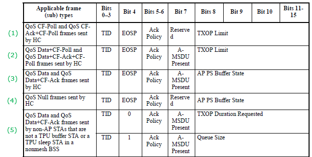
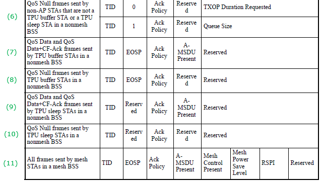
The two images below show one table split into two parts. Each row, numbered (1) to (11) on the left, names a group of frame types and the station that sends them. The columns give the meaning of bits 0-3, bit 4, bits 5-6, bit 7 and bits 8-15 for that row.
Followings are the description of Acronyms shown in the table :
TID (Traffic Identifier) : This is a label used in WiFi networks to classify data packets according to the type of service they require. TID helps in prioritizing traffic by identifying the nature of the data being transmitted, such as voice, video, best effort, or background. This classification allows the network to apply the appropriate QoS policies to ensure that high-priority traffic like voice and video is delivered promptly and efficiently.EOSP (End of Service Period) : This bit marks the end of a service period, not the end of a TXOP. The AP, as the HC, sets it to 1 in the last frame that it delivers to a power-saving station in a service period, for example with U-APSD. When the station sees EOSP = 1, it knows that the AP has nothing more for it in this service period, and it can go back to doze. In the frames that a non-AP STA sends, rows (5) and (6), bit 4 is not EOSP. There it selects what bits 8-15 carry.TXOP (Transmission Opportunity) : This is a specific duration when a device is allowed to send multiple data frames sequentially without competing for access to the wireless medium again. TXOP is crucial for QoS in WiFi because it ensures that once a device starts transmitting, it can continue to send a series of packets based on its priority and QoS requirements. This is particularly important for applications that need continuous data transmission, like video streaming or VoIP, as it helps reduce latency and ensure a stable connection.MSDU (MAC Service Data Unit) : In the context of WiFi networking, an MSDU is the payload or the actual data that needs to be transmitted over the network. It is encapsulated within a MAC protocol data unit (MPDU) for transmission. The MSDU is essentially what you're trying to send over the network, such as a piece of an email, a segment of video, or a portion of a webpage. The process of handling MSDUs efficiently is vital for maintaining good network performance, especially when dealing with QoS to ensure that data packets are delivered in a timely and reliable manner.
Now let's read the table column by column.
Bits 0-3, TID : the same in every row. The next section shows how the TID selects an access category.Bit 4 : EOSP in the frames sent by the HC, rows (1) to (4). In rows (5) and (6), from a non-AP STA, a 0 means that bits 8-15 carry TXOP Duration Requested, and a 1 means that they carry Queue Size.Bits 5-6, Ack Policy : 0 is Normal Ack, 1 is No Ack, 2 is No explicit acknowledgment and 3 is Block Ack.Bit 7 : A-MSDU Present in QoS Data frames. It is reserved in QoS Null frames and in the QoS CF-Poll frames of row (1), because those frames carry no MSDU.Bits 8-15 : TXOP Limit when the HC polls a station, rows (1) and (2). AP PS Buffer State in the other frames from the HC, rows (3) and (4). TXOP Duration Requested or Queue Size from a non-AP STA, rows (5) and (6). Reserved for TPU buffer and TPU sleep STAs, rows (7) to (10). In a mesh BSS, row (11), bits 8, 9 and 10 become Mesh Control Present, Mesh Power Save Level and RSPI.
Read the sender first : the upper byte means TXOP Limit, buffer state, TXOP request or queue size depending on who sent the frame.EOSP belongs to power save : it closes a service period for a dozing station, and it has nothing to do with the end of a TXOP.
How does the TID select an access category ?
The TID field has 4 bits, but a normal QoS Data frame uses only the values 0 to 7. These eight values are the 802.1D user priorities, and EDCA maps them onto four access categories. Values 8 to 15 are used for traffic streams that a station sets up with a TSPEC. The table below lists the mapping for 0 to 7.
TID - User Priority | 802.1D designation | Access Category |
|---|---|---|
1 | Background | AC_BK |
2 | Spare | AC_BK |
0 | Best Effort | AC_BE |
3 | Excellent Effort | AC_BE |
4 | Controlled Load | AC_VI |
5 | Video | AC_VI |
6 | Voice | AC_VO |
7 | Network Control | AC_VO |
Notice that the order of the values is not the order of the priority. User priority 0, Best Effort, sits above 1 and 2, which are Background. Wireshark prints both names for this reason. In the capture below, the line Priority: Best Effort (Best Effort) gives the 802.1D designation first and the access category in brackets.
Each access category then contends for the channel with its own EDCA parameters: AIFSN, CWmin, CWmax and TXOP Limit. The AP announces these values in the EDCA Parameter Set element of its beacons. A smaller AIFSN and a smaller contention window mean a shorter wait, so a frame in AC_VO usually reaches the medium before a frame in AC_BK. The AP can also require admission control for an access category. In that case, the station must set up a TSPEC with the AP before it sends traffic in that category. The CSMA/CA page shows the basic contention that EDCA modifies.
Where does the user priority come from in the first place? The application usually marks its IP packets with a DSCP value, and the WiFi driver turns that DSCP into a user priority. A simple driver takes the top 3 bits of the 6-bit DSCP. That shortcut has a known side effect. Voice traffic is normally marked EF, which is DSCP 46, and 46 shifted right by 3 bits gives 5. So the voice packets land in AC_VI instead of AC_VO. RFC 8325 describes a recommended DSCP to user priority mapping for this reason. When a voice call on WiFi shows poor quality, the TID in the capture is therefore one of the first fields to check.
The TID matters beyond channel access, too. Inside one station, each access category has its own queue and its own backoff counter. If two queues reach zero in the same slot, the station sends the higher-priority frame and treats the other as a collision. A Block Ack agreement is also set up per TID, and QoS Data frames keep a separate sequence number space for each TID. So the Ack Policy bits and the TID bits in the same field work together: the TID names the flow, and the Ack Policy says how that flow is acknowledged.
Eight priorities, four queues : two user priorities share each access category.Priority comes from waiting less : EDCA gives each access category its own AIFSN and contention window, and the AP sets them in its beacons.TID 0 is Best Effort : the frame in the capture below contends as AC_BE.
What does a QoS Data frame look like in a capture ?
A decode shows the same fields in the order they appear on the air. The frame below is a QoS Data frame that a station sent to its AP, so it belongs to row (5) of the table. Watch two numbers in it: the Duration of 60 microseconds and the TXOP Duration Requested of 0. The discussion after the decode explains why both are correct.
This is an example of the structure and content of a QoS Data frame in an IEEE 802.11 (Wi-Fi) network, highlighting how QoS is implemented at the MAC (Media Access Control) layer.
Decoded IEEE 802.11 QoS Data frame,
IEEE 802.11 QoS Data, Flags: .......TC
    Type/Subtype: QoS Data (0x28)
    Frame Control Field: 0x8801
        .... ..00 = Version: 0
        .... 10.. = Type: Data frame (2)
        1000 .... = Subtype: 8
        Flags: 0x01
            .... ..01 = DS status: Frame from STA to DS via an AP (To DS: 1 From DS: 0) (0x01)
            .... .0.. = More Fragments: This is the last fragment
            .... 0... = Retry: Frame is not being retransmitted
            ...0 .... = PWR MGT: STA will stay up
            ..0. .... = More Data: No data buffered
            .0.. .... = Protected flag: Data is not protected
            0... .... = Order flag: Not strictly ordered
    .000 0000 0011 1100 = Duration: 60 microseconds
    Receiver address: Anritsu_07:91:0e (00:00:91:07:91:0e)
    BSS Id: Anritsu_07:91:0e (00:00:91:07:91:0e)
    Transmitter address: e0:cb:ee:f9:4a:de (e0:cb:ee:f9:4a:de)
    Source address: e0:cb:ee:f9:4a:de (e0:cb:ee:f9:4a:de)
    Destination address: Anritsu_07:91:0e (00:00:91:07:91:0e)
    Fragment number: 0
    Sequence number: 13
    Frame check sequence: 0x1adb5852 [correct]
        [Good: True]
        [Bad: False]
    Qos Control: 0x0000
        .... .... .... 0000 = TID: 0
        [.... .... .... .000 = Priority: Best Effort (Best Effort) (0)]
        .... .... ...0 .... = QoS bit 4: Bits 8-15 of QoS Control field are TXOP Duration Requested
        .... .... .00. .... = Ack Policy: Normal Ack (0x0000)
        .... .... 0... .... = Payload Type: MSDU
        0000 0000 .... .... = TXOP Duration Requested: 0 (no TXOP requested)
Let's break down the key parts:
Type/Subtype (0x28) : Indicates this is a QoS Data frame, a type of frame used in Wi-Fi networks to transmit data with Quality of Service considerations.Frame Control Field (0x8801) : This field provides information about the frame:- Version: 0 indicates the Wi-Fi version.
- Type: Data frame (2) specifies that this is a data frame.
- Subtype: 8 identifies it specifically as a QoS Data frame.
- Flags:
- DS status: Frame from STA to DS via an AP (To DS: 1 From DS: 0) indicates the direction of the frame, from the station (STA) to the distribution system (DS), through an access point (AP).
- More Fragments: This is the last fragment means no more fragments follow this frame.
- Retry: Frame is not being retransmitted indicates this is the first transmission of the frame.
- PWR MGT: STA will stay up suggests the sending device will remain active and not go into power-saving mode.
- More Data: No data buffered means the sender does not have more data to send at this moment.
- Protected flag: Data is not protected signifies the frame is not encrypted.
- Order flag: Not strictly ordered indicates the frames are not required to be processed in strict order.
Duration : 60 microseconds specifies the time the channel stays reserved after this frame ends, for the SIFS and the ACK.Addresses : Includes Receiver address, BSS Id (Basic Service Set Identifier), Transmitter address, Source address, and Destination address, identifying the involved devices and network.Fragment number : Identifies the fragment number of the frame, with 0 indicating it's the first or only fragment.Sequence number : 13 is a unique identifier for the frame to keep track of the order of frames.Frame check sequence : A form of error checking to ensure the integrity of the frame's data.QoS Control (0x0000): Provides specific QoS parameters:TID : 0 (Traffic Identifier) and Priority: Best Effort indicate the type of traffic is "Best Effort," which is the default level of service without any special priority.Ack Policy : Normal Ack means the receiver should acknowledge receipt of this frame using standard acknowledgment procedures.Payload Type : MSDU specifies that the payload is a MAC Service Data Unit, the actual data being transmitted.TXOP Duration Requested : 0 indicates no specific transmission opportunity was requested for this frame.
The apparent discrepancy between the "Duration" field being set to 60 microseconds and the "TXOP Duration Requested" being set to 0 in the QoS Control field can be understood by distinguishing the purposes of these two fields in the context of an IEEE 802.11 QoS Data frame. Therefore, there is no conflict between these two fields. The Duration field ensures the successful transmission and acknowledgment of the current frame, while the TXOP Duration Requested indicates that no additional extended transmission time is being requested. This setup is typical for scenarios where the device is either sending data opportunistically, without the need for extended access, or where network conditions or policies do not favor or permit extended TXOP allocations.
Duration Field : This field, set to 60 microseconds, specifies the time period that the medium stays reserved after the frame, which is the SIFS plus the time required for the acknowledgment (ACK) to be received after the frame is transmitted. It's a mechanism used in Wi-Fi networks to prevent other devices from attempting to access the medium immediately after this frame, ensuring that the current transmission is completed successfully and acknowledged without interference. The value is not directly related to the QoS TXOP; rather, it's a standard field in all 802.11 frames that helps manage airtime fairness and efficiency.TXOP Duration Requested (in the QoS Control field) : This part of the QoS Control field specifies the duration that the transmitting station requests to send multiple frames in a single TXOP. A value of 0 means that the frame is not requesting any specific TXOP duration beyond the immediate opportunity to transmit this single frame. In other words, the station is not asking for any additional reserved time on the medium to send more frames back-to-back without competing again for medium access.
The key difference lies in their purpose and context of use:
- The Duration field is used for immediate medium reservation for the current frame and its ACK, applicable to all frames.
- The TXOP Duration Requested specifies a desire for extended transmission rights beyond the immediate frame, relevant only in QoS contexts where multiple frames might be sent in a rapid sequence (burst)
We can check the 60 microseconds with a short calculation. The Duration field of this frame covers what comes after it: one SIFS and the ACK. An ACK frame is 14 octets. The OFDM PHY adds a 16-bit SERVICE field and 6 tail bits, so the ACK carries 16 + 112 + 6 = 134 bits. At 6 Mbps, one 4 microsecond OFDM symbol carries 24 bits, so the ACK needs 6 symbols, or 24 microseconds. The preamble and the SIGNAL field add 20 microseconds, so the ACK lasts 44 microseconds. In the 5 GHz band SIFS is 16 microseconds, and 16 + 44 = 60 microseconds, which is the value in the capture. In the 2.4 GHz band with ERP-OFDM, SIFS is 10 microseconds and a 6 microsecond signal extension follows the ACK, so the total is again 60 microseconds. Either way, the value matches an ACK sent at 6 Mbps.
One flag in the decode also has a newer meaning. Wireshark prints the Order flag as Not strictly ordered, which is its original meaning. In a QoS Data frame, 802.11n reused this bit. When it is 1, the MAC header carries an HT Control field after the QoS Control field. In this capture the bit is 0, so the header ends with the QoS Control field.
Yes, the "Duration" field in an IEEE 802.11 frame corresponds to the Network Allocation Vector (NAV). The NAV is a virtual carrier sensing mechanism used in Wi-Fi networks to inform all other stations in the network about the medium's status, specifically how long the medium will be busy or reserved. This helps in managing access to the wireless medium and in reducing collisions by preventing stations from attempting to transmit while the medium is occupied.
When a Wi-Fi device transmits a frame, it includes in the Duration field the amount of time that the medium will be required after the frame, for the SIFS and the subsequent acknowledgment (ACK) frame, or for the entire frame exchange sequence if multiple frames are involved. Other devices that receive this frame read the Duration field and set their NAV timers accordingly. While the NAV timer is running, these devices refrain from initiating their transmissions, effectively giving the transmitting device exclusive access to the medium for the specified duration.
The Duration field, therefore, plays a critical role in coordinating access to the wireless medium, ensuring that transmissions are orderly and minimizing the likelihood of collisions. By setting the NAV through the Duration field, a device communicates its need for the medium, allowing for more efficient use of the network resources and better overall network performance.
Duration looks forward : it reserves the medium for what follows the frame, here SIFS plus a 6 Mbps ACK, 60 microseconds.A zero TXOP request is normal : the station simply did not ask for a longer TXOP, and it needs none to send this frame.
Reference
- packet-ieee80211.c : Wireshark IEEE 802.11 dissector, used for the QoS Control bit meanings, the Ack Policy values and the 802.1D to access category mapping.