I saw a lot of persons trying to do IP throughput test in most complicated setup (e.g, Case 5 without IP monitoring tool) from the beginning without preparing any troubleshoot tools. If you are lucky, you will get it working. But in most case especially when the user tries the test for the first time with the specific test setup.
But I always recommend user to prepare proper troubleshooting setup first and do some preparational test before you try with the final setup.
For example, if you want to test with < Case 2 > configuration, first try with < Case 1 > Configuration and make it sure that there are no PC related issues.
If you want to try to test with < Case 5> configuration, first try with < Case 1> & < Case 2>, make it sure that there are no router related issue.
Have Wireshark both on UE PC and Server PC in Case 2/ Monitor PC in Case 5. You have to be able to trace each steps of the path described below for each cases.
Does this sound too tedious ? Trust me ! This would be the fastest way to get the solution for any trouble.
The five setups below are ordered by the number of elements in the data path. Case 1 has only two PCs and a cable. Case 2 and Case 3 add the network simulator, the RF connection and a USB link to the UE PC. Case 4 removes the UE PC and runs the client on the UE itself. Case 5 adds a hub, a router and an IP network on the server side. So when a complex setup fails, you can go back one step and find the element that causes the problem.
Followings are various cases of test setup explained in this page.
- Case 1 - PC to PC throughput
- Case 2 - Data Card UE and Server PC
- Case 3 - Mobile Phone UE and Server PC with Tethering
- Case 4 - Mobile Phone UE and Server PC with Local Client - Client installed on UE
- Case 5 - Mobile Phone UE and Server PC with Live Network/Test Network
- Which link limits the throughput for each UE category ?
- Reference
Case 1 - PC to PC throughput
This is not the test for mobile phone, but I recommend you to test your Server PC itself to make it sure that the server PC has enough performance for the throughput to be achieved. I saw many cases where we failed to get the throughput lower than expected not because of UE but because of the server itself. Also, in some cases UDP/TCP or even ping failed to go through due to some firewall settings. To get rid of all these possibility, I recommend you to try this at least when you setup the throughput test environment at initial stage or when you checked all the other components in the test but still fail to find the root cause of trouble.
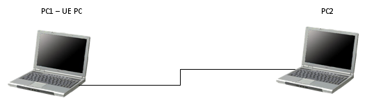
In the diagram above, PC1 is the PC that will later sit behind the UE, and PC2 is the PC that will later act as the server. Only a cable connects them. So any limit you measure here belongs to the two PCs, their network cards or their firewall settings.
Let's run the same traffic that you plan to run over LTE. Start with ping in both directions, because a firewall often blocks only one direction. Then run UDP with iperf at a rate above the target LTE throughput, and then run TCP. If the two PCs cannot reach the target over a plain cable, no UE will reach it either. For a target above 100 Mbps, check that both network cards and the cable support Gigabit Ethernet. A Fast Ethernet card stops at 100 Mbps.
Case 1 sets the ceiling : the PC to PC result is the highest throughput that any later case can show with the same PCs.Test both directions : a firewall can pass ping or UDP in one direction and block it in the other.Repeat it after a PC change : a new PC, a new network driver or a security update can change the result.
Case 2 - Data Card UE and Server PC
This would be the most common test setup for data card type of the devices and the most common/stable demo environment from HSPA to early LTE. Common cases of troughble for this case would be related to USB drive. Also performance may vary whether the device is used as a dial up modem or as a network card.
Recently as LTE Category goes higher, USB specification tend to become the bottleneck of the throughput. With LTE Category 6 or higher, the max throughput is 300 Mbps or higher. Make it sure that your USB on the device and the server PC support enough throughput capacity for this kind of test.
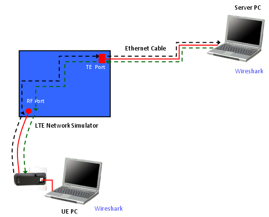
In the diagram above, the red lines are the physical connections. One is the RF cable between the data card and the RF Port, and the other is the Ethernet cable between the TE Port and the Server PC. The black dashed line follows the ping request from the data card to the Server PC. The green dashed line follows the ping reply back to the data card. Wireshark runs on both PCs, so you have a capture at each end of the path. The ping path below lists the same steps in text.
Ping Path from UE PC to Server PC :
Ping Request : UE PC -(1)-> UE IP Driver -(2)-> UE PDCP -(3)-> UE RLC -(4)-> UE MAC -(5)-> UE PHY
-(6)-> RF Connection -(7)-> Equipment PHY -(8)-> Equipment MAC -(9)-> Equipment RLC
-(10)-> Equipment PDCP -(11)-> Equipment TE -(12)-> Network Interface Card on Server PC
Ping Reply : Server PC -(1)-> Equipment TE -(2)-> Equipment PDCP -(3)-> Equipment RLC -(4)-> Equipment MAC
-(5)-> Equipment PHY -(6)-> RF Connection -(7)-> UE PHY -(8)-> UE MAC -(9)-> UE RLC
-(10)-> UE PDCP -(11)-> UE IP Driver -(12)-> Network Interface on UE PC
NOTE : (2) in Ping Request is usually USB cable. (12) in Ping Request is usually Ethernet Cable.
The two captures split the path in half. Suppose Wireshark on the UE PC shows the request going out. If Wireshark on the Server PC never shows it, the problem is in the uplink part of the path. That means the UE, the RF connection or the equipment. If the Server PC receives the request and sends the reply, but the UE PC never receives it, the problem is on the downlink side. After that, the UE logging tool and the equipment log narrow it down to one layer.
Capture at both ends : two Wireshark captures tell you which half of the path loses the packet.USB is part of the data path : step (2) of the ping request crosses the USB cable, so a USB driver problem can look like a radio problem.Check the USB version for high categories : USB 2.0 High Speed signals at 480 Mbps, and the usable data rate is lower than that.
Case 3 - Mobile Phone UE and Server PC with Tethering
This configuration used to be used often upto LTE Cat 3 or Cat 4 in which UE side chipset performance is not high enough to handle very high throughput data.
Common cases of troughble for this case would be related to USB drive. Also performance may vary whether the device is used as a dial up modem or as a network card.
Recently as LTE Category goes higher, USB specification tend to become the bottleneck of the throughput. With LTE Category 6 or higher, the max throughput is 300 Mbps or higher. Make it sure that your USB on the device and the server PC support enough throughput capacity for this kind of test.
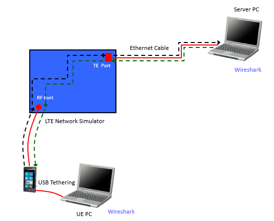
The diagram above differs from Case 2 in one element. A phone replaces the data card, and the UE PC reaches the phone over USB Tethering. The ping path is the same, but the phone now does more work than a modem does. In most phones, tethering works as a router with NAT between the USB link and the LTE connection.
Ping Path from UE PC to Server PC :
Ping Request : UE PC -(1)-> UE IP Driver -(2)-> UE PDCP -(3)-> UE RLC -(4)-> UE MAC -(5)-> UE PHY
-(6)-> RF Connection -(7)-> Equipment PHY -(8)-> Equipment MAC -(9)-> Equipment RLC
-(10)-> Equipment PDCP -(11)-> Equipment TE -(12)-> Network Interface on Server PC
Ping Reply : Server PC -(1)-> Equipment TE -(2)-> Equipment PDCP -(3)-> Equipment RLC -(4)-> Equipment MAC
-(5)-> Equipment PHY -(6)-> RF Connection -(7)-> UE PHY -(8)-> UE MAC -(9)-> UE RLC
-(10)-> UE PDCP -(11)-> UE IP Driver -(12)-> Network Interface on UE PC
NOTE : (2) in Ping Request is usually USB cable. (12) in Ping Request is usually Ethernet Cable.
The NAT has two practical results. First, the UE PC usually gets a private IP address from the phone, not the address that the network assigned to the UE. So the Server PC sees the LTE address of the phone as the source address. Also, the NAT may drop a ping or a UDP stream that the Server PC starts toward the UE PC. Second, the phone CPU forwards every packet between USB and LTE, so it can become the bottleneck before the radio link does. Run ipconfig on the UE PC before you start, and compare its address with the source address in the Server PC capture.
The phone is a router in this setup : its NAT hides the UE PC address from the Server PC.Start the first test from the UE PC : traffic that starts on the UE PC side passes the NAT without extra settings.Watch the phone CPU : forwarding at a high rate loads the application processor of the phone as well as its modem.
Case 4 - Mobile Phone UE and Server PC with Local Client - Client installed on UE
For a long time we have been using a tethering PC connected to UE to achieve high throughput, but recently the chipset performance on UE is almost up to PC performance and many USB interface either on UE or on PC failed to catch up the latest specificaiton, the configuration shown below is getting used more often. Just install Data Apps like iperf or ftp tools directly onto UE and perform the throughput test. As far as I have tried (as of Oct 2015), the highest throughput I got with this configuration was 360 Mbps with 3 CC (20+20+10Mhz).
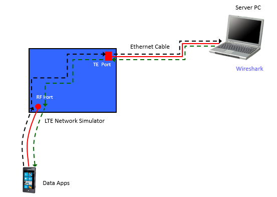
In the diagram above, the Data Apps run on the phone itself. The only cable in the path is the Ethernet cable between the TE Port and the Server PC. There is no UE PC, so there is no Wireshark capture at the UE end. For the UE side, you depend on the log of the data app and on the UE logging tool.
Followings are some examples of client (Data App on UE) and Server (Data Application on Server PC) that I have tried.
For pure max throughput especially over 100 Mbps, you would need to use item i) combination, but for moderate throughput (below 100 Mbps) and in more realistic situation, I recommend you to try with combination ii) or iii).
i) Client : Iperf for Android, Server : Iperf
ii) Client : AndFTP, Server : FileZilla (with Max Buffer Size)
iii) Client : Web Browser that support ftp, Server : FileZilla (with Max Buffer Size)
Ping Path from UE PC to Server PC :
Ping Request : UE Data App -(1)-> UE IP Stack -(2)-> UE PDCP -(3)-> UE RLC -(4)-> UE MAC -(5)-> UE PHY
-(6)-> RF Connection -(7)-> Equipment PHY -(8)-> Equipment MAC -(9)-> Equipment RLC
-(10)-> Equipment PDCP -(11)-> Equipment TE -(12)-> Network Interface on Server PC
Ping Reply : Server PC -(1)-> Equipment TE -(2)-> Equipment PDCP -(3)-> Equipment RLC -(4)-> Equipment MAC
-(5)-> Equipment PHY -(6)-> RF Connection -(7)-> UE PHY -(8)-> UE MAC -(9)-> UE RLC
-(10)-> UE PDCP -(11)-> UE IP Stack -(12)-> UE Data App
NOTE : (12) in Ping Request is usually Ethernet Cable.
Two checks save time in this setup. First, turn off WiFi on the phone, or make sure that the data app really uses the LTE connection. Otherwise the app may send its traffic over WiFi, and the result tells you nothing about LTE. Second, the app shares the phone CPU with the modem software and the operating system. So a low result may come from the app rather than from the radio link. Try another client from the list above before you suspect the radio link.
No USB in the path : this is why the setup reaches rates that a USB 2.0 link cannot carry.Turn off WiFi : a phone with WiFi on may route the test traffic away from LTE.The app is part of the path : compare two clients before you blame the UE modem.
Case 5 - Mobile Phone UE and Server PC with Live Network/Test Network
This setup brings the test closer to a real network. The Server PC no longer connects directly to the TE Port. Instead, the path runs through a Dummy Hub, a Router and an IP Network. It is also the setup with the most places to fail, so try it last, after Case 1 and Case 2 work.
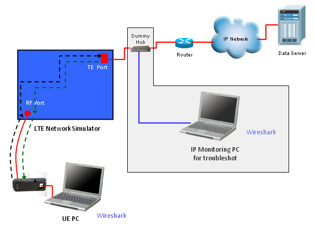
In the diagram above, the Dummy Hub sits between the TE Port and the Router. An IP Monitoring PC with Wireshark is connected to the hub. A hub repeats every frame to all of its ports, so the monitoring PC sees all traffic between the equipment and the router. A switch forwards only the frames addressed to each port, so it would hide that traffic unless you set up port mirroring. The UE side is the data card and the UE PC from Case 2, so the Wireshark capture on the UE PC is available too.
Ping Path from UE PC to Server PC :
Ping Request : UE PC -(1)-> UE IP Driver -(2)-> UE PDCP -(3)-> UE RLC -(4)-> UE MAC -(5)-> UE PHY
-(6)-> RF Connection -(7)-> Equipment PHY -(8)-> Equipment MAC -(9)-> Equipment RLC
-(10)-> Equipment PDCP -(11)-> Equipment TE -(12)-> Dummy Hub -(13)-> Router
-(14)-> Network Interface on Server PC
Ping Reply : Server PC -(1)-> Router -(2)-> Dummy Hub -(3)-> Equipment TE -(4)-> Equipment PDCP
-(5)-> Equipment RLC -(6)-> Equipment MAC -(7)-> Equipment PHY -(8)-> RF Connection
-(9)-> UE PHY -(10)-> UE MAC -(11)-> UE RLC -(12)-> UE PDCP -(13)-> UE IP Driver
-(14)-> Network Interface on UE PC
NOTE : (12) in Ping Request is usually Ethernet Cable.
Note one difference between the text and the drawing. The ping path above ends at the Server PC right after the Router. The drawing puts an IP Network and a Data Server behind the Router. The steps up to the Router are the same in both, so the Dummy Hub capture is valid for either.
The hub has a cost. A hub works in half duplex, and most hubs run at 10 or 100 Mbps. So all traffic through the hub shares one 100 Mbps link. That is enough for early LTE categories, but it caps the throughput well below the peak of a Category 4 or higher UE. For a high throughput test, replace the hub with a Gigabit switch that supports port mirroring, and mirror the TE Port to the monitoring PC.
The hub gives visibility : every frame between the equipment and the router reaches the monitoring PC.The hub also limits the rate : a 10/100 Mbps half duplex hub cannot carry a Category 4 peak rate.Use port mirroring above 100 Mbps : a Gigabit switch with a mirrored TE Port gives the same capture without the limit.
Which link limits the throughput for each UE category ?
Every case above puts at least one PC interface in the data path, and that interface must carry the peak rate of the UE. So before you choose a setup, compare the peak rate of the UE category with the rate of each link. TS 36.306 gives the maximum number of DL-SCH transport block bits that a UE of each category receives within a TTI. One TTI is 1 ms, so this number divided by 1000 is the peak physical layer rate in Mbps.
UE Category | Max DL-SCH TB bits within a TTI | Peak DL rate, Mbps | Links that can carry the peak |
Category 3 | 102048 | 102.048 | Gigabit Ethernet. Fast Ethernet at 100 Mbps is already too slow |
Category 4 | 150752 | 150.752 | Gigabit Ethernet, USB 2.0 |
Category 6 | 301504 | 301.504 | Gigabit Ethernet, USB 3.0 recommended |
Category 9 | 452256 | 452.256 | Gigabit Ethernet, USB 3.0. This is close to the 480 Mbps signalling rate of USB 2.0 |
Category 12 | 603008 | 603.008 | Gigabit Ethernet, USB 3.0. This is above the signalling rate of USB 2.0 |
The peak rate is a physical layer number. The IP rate is a few percent lower after the protocol headers and the control overhead. Even so, the links have to carry bursts close to the peak. Fast Ethernet runs at 100 Mbps and Gigabit Ethernet at 1000 Mbps, so only Gigabit Ethernet covers every row. The USB column matters only for Case 2 and Case 3. Case 4 has no USB link, which is one reason that it became common for Category 6 and higher.
Uplink is less demanding. For example, TS 36.306 limits a Category 3, 4, 6 or 9 UE to 51024 UL-SCH transport block bits within a TTI, which is about 51 Mbps. So in most setups, the downlink peak decides which links you need.
Compare the category with every link : the slowest link in the path decides the highest throughput you can measure.Gigabit Ethernet is the minimum : Fast Ethernet cannot carry even the Category 3 peak of 102.048 Mbps.USB 2.0 runs out above Category 6 : a Category 9 or higher test needs USB 3.0 or the setup of Case 4.
Reference
[1] 3GPP TS 36.306 v19.3.0 - E-UTRA, User Equipment radio access capabilities, Table 4.1-1 and Table 4.1-2