|
|
||
|
In most of simple operations or representations, I used the qbit state circle as shown here. It is very simple and easy to understand, but the Qbit state circle has restrictions. Since it is only in 2 dimension, it cannot represent the result of operation that requires 3D representation. On top of it, it cannot represent the state function that has imaginary probability compoment. There is another way of visualizing a qbit that can overcome all the restrictions mentioned above. It is called Bloch Sphere which is named after the person (Felix Bloch) who invented the concept. The Bloch sphere is a 3-dimensional sphere, where any point on the surface of the sphere represents a unique pure state of a qubit. The north and south poles of the Bloch sphere usually represent the basis states |0⟩ and |1⟩, respectively. Any other point on the surface of the sphere represents a linear combination (superposition) of these basis states. The Bloch sphere provides a useful visualization of the state of a qubit, as well as the transformations (quantum gates) that can be applied to it. It is widely used in quantum computing and quantum information theory to represent and analyze the behavior of qubits.
Build Up IntuitionBefore delving into the intricate mathematical formalism behind the Bloch Sphere, we'll first build an intuitive understanding through this interactive simulator. This tool allows you to directly manipulate key parameters and observe their impact on a quantum state's representation. Specifically, you'll be able to adjust the polar angle and azimuthal angle, which are the two fundamental parameters dictating the position of a vector—visually represented by a red disk—on the sphere's surface. While the interface presents additional controls, these are primarily cosmetic; the polar and azimuthal angles are the sole determinants of a quantum state's position on the Bloch sphere. By experimenting with these settings, you'll gain a tangible grasp of how these angles define a quantum state's orientation and, consequently, its properties.
|ψ⟩ = cos(0.00/2)|0⟩ + ei0.00sin(0.00/2)|1⟩
Bloch Sphere Controls
Bloch Sphere Visualization - Usage GuideThis interactive Bloch sphere visualization tool is designed to help you explore quantum states in an intuitive and visually engaging way. Rather than diving straight into complex equations, this interface allows you to manipulate key parameters—like the polar and azimuthal angles—and immediately see their impact on the quantum state's representation on the Bloch sphere. As you adjust these angles, you'll observe how the quantum state vector moves on the surface of the sphere, providing a hands-on understanding of how qubits behave. Whether you're rotating the sphere with your mouse, changing display modes, or selecting standard quantum states from a dropdown menu, each interaction updates the mathematical expression of the state in real-time. This makes it easier to connect geometric movements with quantum mechanical formulas. The visualization also includes helpful features like trace history, color-coded reference axes, and state presets to support learning. Overall, this tool serves as a bridge between abstract theory and tangible experience, giving learners a deeper intuition for how qubit states are formed, transformed, and interpreted in quantum computing.
The quantum state is represented as: |ψ⟩ = cos(θ/2)|0⟩ + eiφsin(θ/2)|1⟩ Where θ and φ are the angles you set with the sliders. Bloch Sphere Intuition Explorer: Sample ActivitiesBefore diving into the mathematical formalism of quantum states, it's helpful to get a visual and intuitive feel for how qubit states behave on the Bloch sphere. This simulator lets you adjust the polar angle (θ) and azimuthal angle (φ), which together define the orientation of a quantum state vector in three-dimensional space. By seeing how the vector moves on the sphere as you change these angles, you begin to internalize the geometric representation of qubits, including the differences between basis states, superposition states, and phase shifts. You can explore how quantum gates like Hadamard and Pauli-X affect the state, or how phase manipulation shifts the vector around the equator.
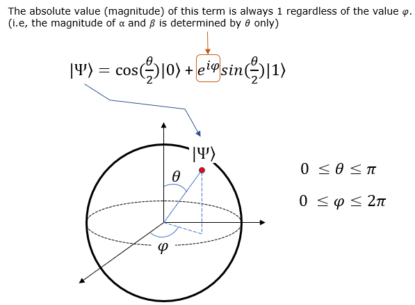
Definition of Bloch SphereSimply put, Bloch Sphere is a way to respresent a qbit states in a 3D spherical coordinates. As you know, Spherical Coordinates is a system defined by R (radius), theta and phi. In Bloch sphere, R is fixed to 1. Only Phi and Theta are variable. The qbit state function in the Bloch Sphere is defined as follows.
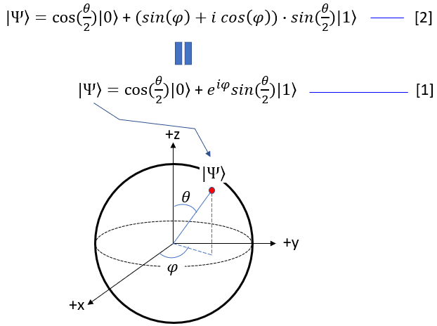
In case not familiar with Euler form of the equation and for easy calculation, we can rewrite the above formula as the equation [2] shown below.
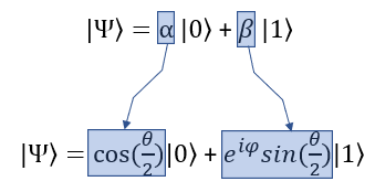
Even though the qbit state function on Bloch sphere looks a little bit complicated, it is still in the form of probability for two qbit state |0> and |1>. The probability of |0> and |1> (alpha and beta) is transformed into a little bit complicated form in Bloch sphere as shown below. Here you would notice that the probability of |1> can be expressed in complex number.
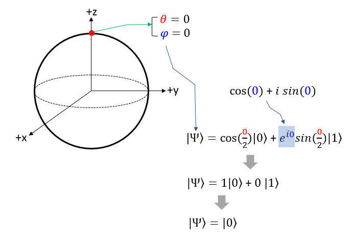
Bloch Vectors on each AxisNow for practice, let's think of some of the important points in the coordinate and how it is expressed in state function. Let's take the point on the circumference that crosses the +z axis. In spherical coordinate, this point is where theta = 0 and phi = 0. If you plug these values into Bloch sphere state function you will get |0> as shown below.
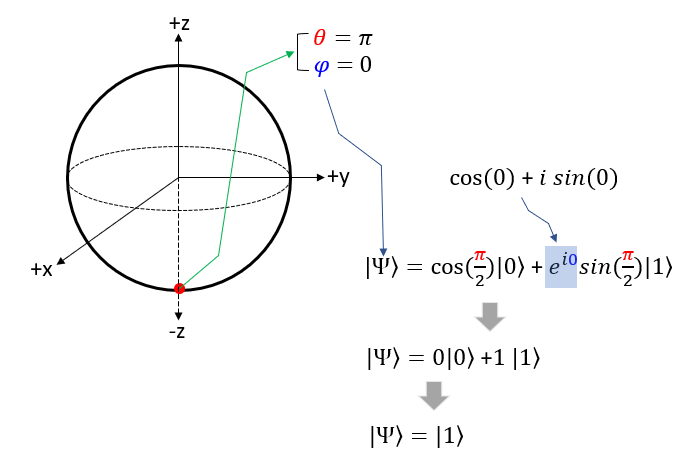
Now Let's take the point on the circumference that crosses the -z axis. In spherical coordinate, this point is where theta = pi and phi = 0. If you plug these values into Bloch sphere state function you will get |1> as shown below.
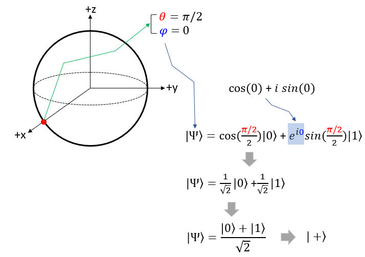
Now Let's take the point on the circumference that crosses the -z axis. In spherical coordinate, this point is where theta = pi/2 and phi = 0. If you plug these values into Bloch sphere state function you will get the function with the same proability of |0> and |1> as shown below. In many documents, you would see this function is represented to be |+> for simplicity.
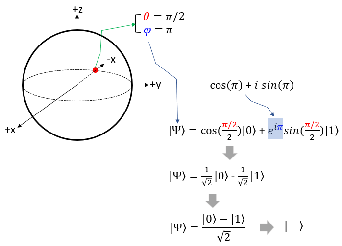
Now Let's take the point on the circumference that crosses the -x axis. In spherical coordinate, this point is where theta = pi/2 and phi = pi. If you plug these values into Bloch sphere state function you will get the function with the same proability of |0> and |1> as shown below. In many documents, you would see this function is represented to be |-> for simplicity.
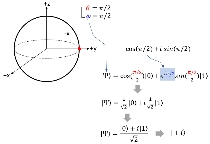
Now Let's take the point on the circumference that crosses the +y axis. In spherical coordinate, this point is where theta = pi/2 and phi = pi. If you plug these values into Bloch sphere state function you will get the function with the same proability of |0> and |1> , but the probability of |1> is imaginary number as shown below. In many documents, you would see this function is represented to be |+i> for simplicity.
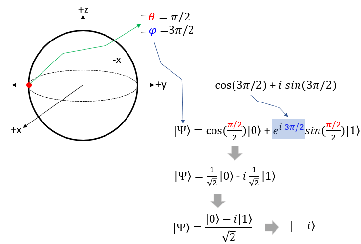
Now Let's take the point on the circumference that crosses the -y axis. In spherical coordinate, this point is where theta = pi/2 and phi = pi. If you plug these values into Bloch sphere state function you will get the function with the same proability of |0> and |1> , but the probability of |1> is imaginary number as shown below. In many documents, you would see this function is represented to be |-i> for simplicity.
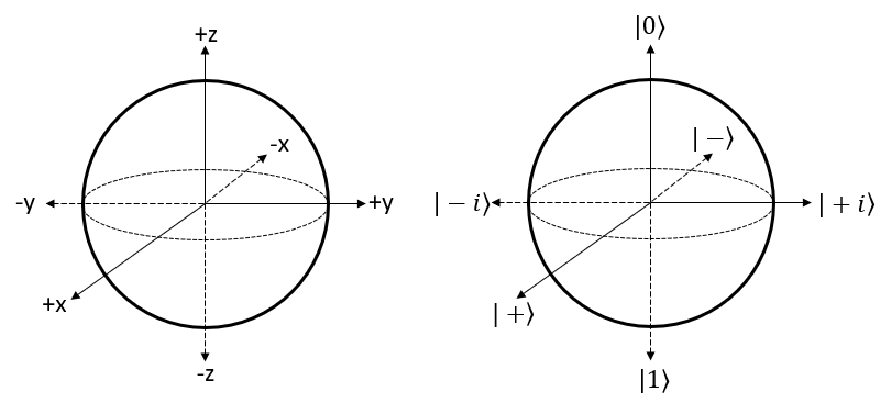
Putting All TogetherPutting together all the examples shown in previous section, the labels on the coordinate left side can be renamed as shown on right ? In many technical document about Bloch Sphere uses the labels shown on right. So try to get familiar to this labeling.
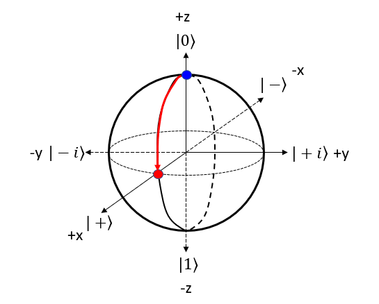
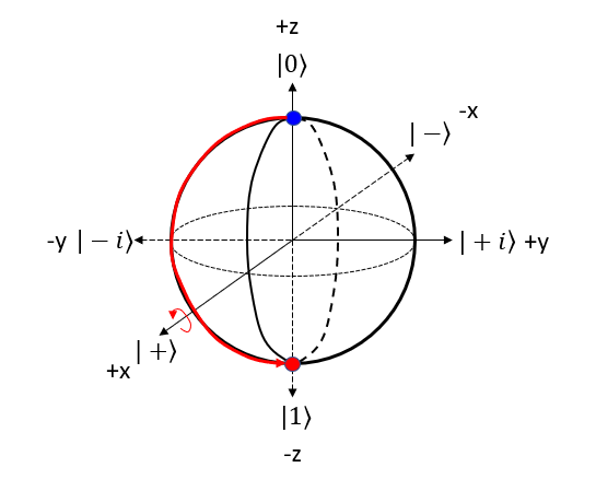
Gate on Bloch SphereYou can represent A quantum gate operation as a transformation on the Bloch sphere. When a gate operates on a qubit, it changes the qubit's state. In the Bloch sphere representation, this is equivalent to rotating the point representing the qubit's state around a specific axis. The procedure to represent the gate operation on bloch sphere can be summarized as follows : Step 1 : Choose the gate: Pick the quantum gate you want to use on the qubit, like Pauli-X, Pauli-Y, Pauli-Z, Hadamard (H), or phase (S) gates. Step 2 : Find the rotation axis: Each quantum gate rotates the qubit around a specific axis on the Bloch sphere. For example, Pauli-X gate uses the X-axis, Pauli-Y gate uses the Y-axis, and Pauli-Z gate uses the Z-axis. Step 3 : Find the rotation angle: Each quantum gate has a rotation angle. For example, Pauli-X, Pauli-Y, and Pauli-Z gates rotate the qubit by 180 degrees (π radians) around their axes. The Hadamard gate rotates the qubit by 180 degrees around an axis that is 45 degrees between the X and Z axes. Step 4 : Rotate the qubit: Rotate the point representing the qubit's state around the chosen axis by the specific angle. The new point on the sphere shows the qubit's state after the gate operation. Hadamard GateThe Hadamard (H) gate is a single-qubit gate that creates a superposition of |0> and |1> states when applied to a qubit. When the Hadamard gate is applied to the |0⟩ state, it transforms the qubit into an equal superposition of |0> and |1> states. NOTE : Compare this operation with the mathemtical opeartion of H Gate. Let's represent H gate operation of |0> bit in 4 steps described above. Step 1 : Choose the gate: Pick the quantum gate you want to use on the qubit ==> It is H Gate Step 2 : Find the rotation axis: Each quantum gate rotates the qubit around a specific axis on the Bloch sphere. ==> It is y axis. rotate on x-z plane. Step 3 : Find the rotation angle: Each quantum gate has a rotation angle. ==> it is 90 degree Step 4 : Rotate the qubit: Rotate the point representing the qubit's state around the chosen axis by the specific angle. ==> New points is marked 'Red' dot as follows.
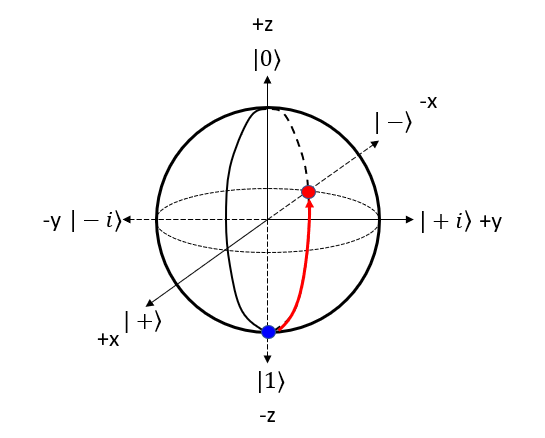
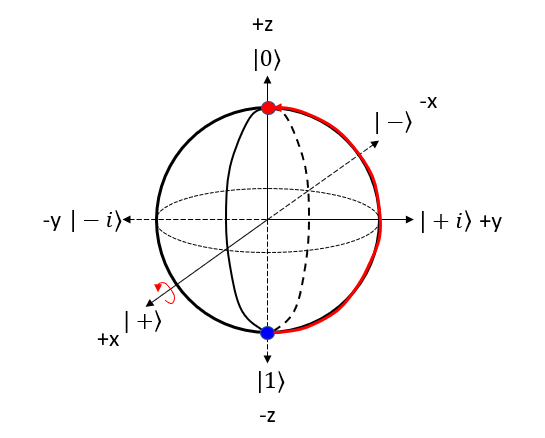
Let's represent H gate operation of |1> bit in 4 steps described above. Step 1 : Choose the gate: Pick the quantum gate you want to use on the qubit ==> It is H Gate Step 2 : Find the rotation axis: Each quantum gate rotates the qubit around a specific axis on the Bloch sphere. ==> It is y axis. rotate on x-z plane. Step 3 : Find the rotation angle: Each quantum gate has a rotation angle. ==> it is 90 degree Step 4 : Rotate the qubit: Rotate the point representing the qubit's state around the chosen axis by the specific angle. ==> New points is marked 'Red' dot as follows.
X GateThe X gate, also known as the Pauli-X gate or the bit-flip gate, is a single-qubit gate that flips the state of a qubit. When applied to the |0⟩ state, it transforms the qubit into the |1⟩ state, and vice versa. NOTE : Compare this operation with the mathemtical opeartion of X Gate. Let's represent X gate operation of |0> bit in 4 steps described above. Step 1 : Choose the gate: Pick the quantum gate you want to use on the qubit ==> It is X Gate Step 2 : Find the rotation axis: Each quantum gate rotates the qubit around a specific axis on the Bloch sphere. ==> It is x axis. rotate on y-z plane. Step 3 : Find the rotation angle: Each quantum gate has a rotation angle. ==> it is 180 degree Step 4 : Rotate the qubit: Rotate the point representing the qubit's state around the chosen axis by the specific angle. ==> New points is marked 'Red' dot as follows.
Let's represent X gate operation of |1> bit in 4 steps described above. Step 1 : Choose the gate: Pick the quantum gate you want to use on the qubit ==> It is X Gate Step 2 : Find the rotation axis: Each quantum gate rotates the qubit around a specific axis on the Bloch sphere. ==> It is x axis. rotate on y-z plane. Step 3 : Find the rotation angle: Each quantum gate has a rotation angle. ==> it is 180 degree Step 4 : Rotate the qubit: Rotate the point representing the qubit's state around the chosen axis by the specific angle. ==> New points is marked 'Red' dot as follows.
Y GateThe Y gate, also known as the Pauli-Y gate, is a single-qubit gate that applies a combination of a bit-flip and a phase-flip to a qubit. When applied to the |0⟩ state, it transforms the qubit into the -i * |1> state, where i is the imaginary unit. NOTE : Compare this operation with the mathemtical opeartion of Y Gate. Let's represent Y gate operation of |0> bit in 4 steps described above. Step 1 : Choose the gate: Pick the quantum gate you want to use on the qubit ==> It is Y Gate Step 2 : Find the rotation axis: Each quantum gate rotates the qubit around a specific axis on the Bloch sphere. ==> It is y axis. rotate on x-z plane. Step 3 : Find the rotation angle: Each quantum gate has a rotation angle. ==> it is 180 degree Step 4 : Rotate the qubit: Rotate the point representing the qubit's state around the chosen axis by the specific angle. ==> New points is marked 'Red' dot as follows.
Let's represent Y gate operation of |1> bit in 4 steps described above. Step 1 : Choose the gate: Pick the quantum gate you want to use on the qubit ==> It is Y Gate Step 2 : Find the rotation axis: Each quantum gate rotates the qubit around a specific axis on the Bloch sphere. ==> It is y axis. rotate on x-z plane. Step 3 : Find the rotation angle: Each quantum gate has a rotation angle. ==> it is 180 degree Step 4 : Rotate the qubit: Rotate the point representing the qubit's state around the chosen axis by the specific angle. ==> New points is marked 'Red' dot as follows.
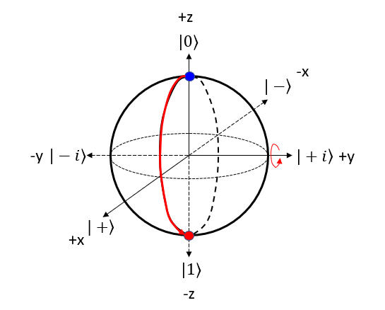
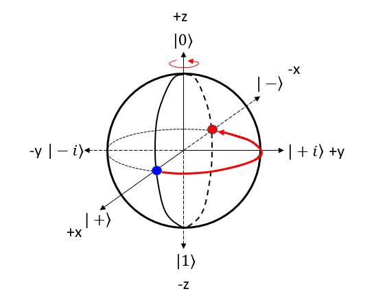
Z GateThe Z gate, also known as the Pauli-Z gate or the phase-flip gate, is a single-qubit gate that applies a phase shift to the qubit state. NOTE : Compare this operation with the mathemtical opeartion of Z Gate. Let's represent Z gate operation of (|0> + |1>)/sqrt(2) bit in 4 steps described above. Step 1 : Choose the gate: Pick the quantum gate you want to use on the qubit ==> It is Z Gate Step 2 : Find the rotation axis: Each quantum gate rotates the qubit around a specific axis on the Bloch sphere. ==> It is z axis. rotate on x-y plane. Step 3 : Find the rotation angle: Each quantum gate has a rotation angle. ==> it is 180 degree Step 4 : Rotate the qubit: Rotate the point representing the qubit's state around the chosen axis by the specific angle. ==> New points is marked 'Red' dot as follows.
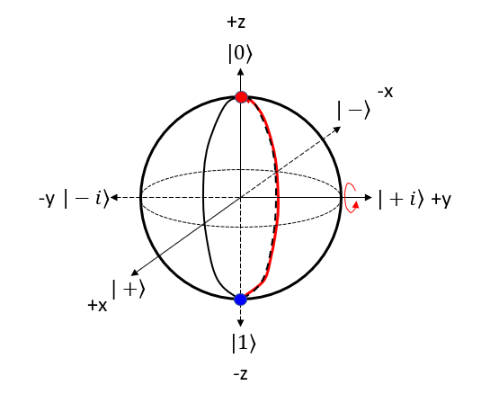
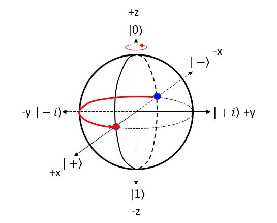
Let's represent Z gate operation of (|0> - |1>)/sqrt(2) bit in 4 steps described above. Step 1 : Choose the gate: Pick the quantum gate you want to use on the qubit ==> It is Z Gate Step 2 : Find the rotation axis: Each quantum gate rotates the qubit around a specific axis on the Bloch sphere. ==> It is z axis. rotate on x-y plane. Step 3 : Find the rotation angle: Each quantum gate has a rotation angle. ==> it is 180 degree Step 4 : Rotate the qubit: Rotate the point representing the qubit's state around the chosen axis by the specific angle. ==> New points is marked 'Red' dot as follows.
Reference :[1] The Bloch Sphere (simply explained) [3] Quantum Optics || 06 The Bloch Sphere 7 24
|
||