For many people working in LTE, one of the most important question would be what is the maximum throughput for a network, device or network operator. The throughput for a device working in a live network would vary at every moment as you can see this drive test. If you knows of the MCS, Number of RBs scheduled by eNB (Network), you can calculate the throughput as in FDD Throughput Calculation and TDD Throughput Calculation page. However, if you ask what is the maximum achievavle throughput for a network or device if we assume that all the resources are allocated to a single UE(device) and signal quality is at the best condition, there is a relatively easy way to estimate it. You can estimate the ideal throughput from UE Category specification. However, it would not be so intuitive to get the throughput information from the table if you don't know the meaning of the numbers in the table. Even if you know the meaning, it would be cumbersome to do calculations everytime you look into the table and this calculation gets more annoying as UE Category gets higher since there are more possible combinations to achieve the desired throught and the calculation gets a little bit different depending on each of the combinations. In this page, I will try to explan the meaning of some numbers which is directly related to throughput calculation and put down some examples that are commonly used so that you don't have to keep abusing your brain every time you look into the table.
Before the examples, keep two facts in mind. The category table gives a PHY layer limit in bits per TTI, and one TTI is 1 ms. So every number on this page is a peak at the PHY layer. The throughput at the application is always lower.
- Reading the UE Category Table
- Category 6
- Category 9
- Category 11
- Case 1 : 4CC CA - 2x2 64 QAM + 2x2 64 QAM + 2x2 64 QAM + 2x2 64 QAM
- Case 2 : 3CC CA - 2x2 256 QAM + 2x2 256 QAM + 2x2 256 QAM
- Case 3 : 2CC CA - 4x4 64 QAM + 4x4 64 QAM
- Case 4 : 2CC CA - 4x4 256 QAM + 2x2 256 QAM
- Category 12
- Case 1 : 4CC CA - 2x2 64 QAM + 2x2 64 QAM + 2x2 64 QAM + 2x2 64 QAM
- Case 2 : 3CC CA - 2x2 256 QAM + 2x2 256 QAM + 2x2 256 QAM
- Case 3 : 2CC CA - 4x4 64 QAM + 4x4 64 QAM
- Case 4 : 2CC CA - 4x4 256 QAM + 2x2 256 QAM
- Category 15
- Case 1 : 4CC CA - 2x2 256 QAM + 2x2 256 QAM + 2x2 256 QAM + 2x2 256 QAM
- Case 2 : 3CC CA - 4x4 256 QAM + 2x2 256 QAM + 2x2 256 QAM
- Category 16
- Case 1 : 5CC CA - 2x2 256 QAM + 2x2 256 QAM + 2x2 256 QAM + 2x2 256 QAM + 2x2 256 QAM
- Case 2 : 3CC CA - 4x4 256 QAM + 4x4 256 QAM + 2x2 256 QAM
- Category 18
- Case 1 : 4CC CA - 4x4 64 QAM + 4x4 64 QAM + 4x4 64 QAM + 4x4 64 QAM
- Case 2 : 5CC CA - 4x4 64 QAM + 4x4 64 QAM + 2x2 256 QAM + 2x2 256 QAM + 2x2 256 QAM
- Case 3 : 6CC CA - 2x2 256 QAM + 2x2 256 QAM + 2x2 256 QAM + 2x2 256 QAM + 2x2 256 QAM + 2x2 256 QAM
- Category 19
- Case 1 : 4CC CA - 4x4 256 QAM + 4x4 256 QAM + 4x4 256 QAM + 4x4 256 QAM without alternativeTBS-Index-r14
- Case 2 : 4CC CA - 4x4 256 QAM + 4x4 256 QAM + 4x4 256 QAM + 4x4 256 QAM with alternativeTBS-Index-r14
- Category 20
- Case 1 : 5CC CA - 4x4 256 QAM + 4x4 256 QAM + 4x4 256 QAM + 4x4 256 QAM + 4x4 256 QAM without alternativeTBS-Index-r14
- Case 2 : 5CC CA - 4x4 256 QAM + 4x4 256 QAM + 4x4 256 QAM + 4x4 256 QAM + 4x4 256 QAM with alternativeTBS-Index-r14
- Categories after Category 20
- Reference
Reading the UE Category Table
Let's start with the columns of the 36.306 category table, because only two of them set the peak rate. Column (A) limits all transport blocks together in one TTI. Column (B) limits one transport block. The categories on this page come from 36.306 Table 4.1-1 for ue-Category and Table 4.1A-1 for ue-CategoryDL.
The parameters that are directly involved in the max throughput estimation are highlighted as below.
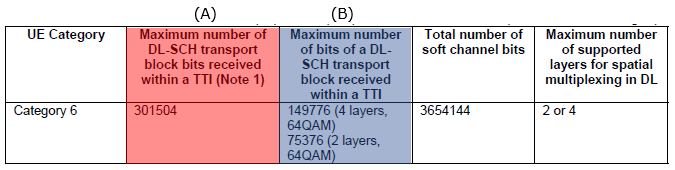
The meaning and how they are related to the throughput estimation is as follows.
Ideal Max Throughput (bits) / sec = (A) x 1000
Ideal Max Transport Block Size (bits) = (B)
Ideal Max Data Rate (bits) / TTI in MIMO = (B) x 2
Is there any relationship between (A) and (B). How (B) is related to (A) if any ?
The answer is Yes, these two numbers are closely related.
If the transport block size is same for all the component carriers(CC) which comprises the system, The relation can be described as follows.
(A) = (B) x N
What does N mean ? It is the total number of layers in the system. For example, if a system of made up of 2 CC and each CC is 2x2 MIMO(64QAM) in the table above. N becomes 4. And (A) and (B) are related as follows.
301504 = 75376 x 4
However when CC(Component Carrier) are using different TBS (i.e, different (B)), the relationship can be a little bit more complicated as below (just an example). You will see more of this kind of examples as UE Category goes higher
(A) = (BCC1) x NCC1 + (BCC2) x NCC2 + ... ,
where BCC1 is (B) for CC1, NCC1 is number of layers for CC1 and so on.
One detail makes the relation (A) = (B) x N exact only for 2-layer values. With 2 layers, each transport block maps to one layer. With 4 layers, each transport block spans two layers, and its TBS comes from the 2-layer translation table, 36.213 Table 7.1.7.2.2-1. The 4-layer value 149,776 is 976 bits less than 2 x 75,376. So a 4x4 carrier always gives a little less than two 2x2 carriers at the same modulation, and several cases below show that gap.
Now we will look into many example for a several selected UE Categories. These are only some of the examples, not the exhaustive combinations. I think these examples would show you most of the combinations that you might have seen in the field.
NOTE : Each of the examples, you will see a digram illustrating a overal data flow structure of a eNB. However, the diagram shows only a type of eNB used in the combination, it does not show all of the eNBs in the system. There is a room barely enough for only one or two eNBs in the page. That's why I couldn't draw all the eNBs in the system.
For example, if you see only one eNB diagram and the system is made up of 3 CC. It means the system is using the 3CCs with the same eNB structure (i.e same antenna configuration). If you see two eNB diagram for the 3CC CA system, it means the system is made up of combining those two types of eNB(e.g, two 2x2 eNB + one 4x4 eNB).
Column (A) sets the peak rate : multiply it by 1000 to get the PHY layer peak in bits per second.Column (B) is per transport block : a CC with two codewords carries up to 2 x (B) bits per TTI.The layer count in (B) matters : the 4-layer value is a little less than twice the 2-layer value.Mixed CCs are added one by one : sum the per-CC values, then compare the total with (A).
Category 6
Maximum Throughput for Category 6 is 301,504,000 bits (around 300 Mbps) and this can be implemented in a couple of different ways as shown in the follows examples.
Category 6 came with Release 10 carrier aggregation, and it is signalled in ue-Category-v1020 together with Categories 7 and 8. It allows two ways to reach about 300 Mbps, and the two cases below show both.
Case 1 : 2CC CA - 2x2 64 QAM + 2x2 64 QAM
In this example, Catetory 6 is implemented by 2CC Carrier aggregation as illustrated below. The two CC (Component Carrier) uses the same antenna configuration as illustrated below.
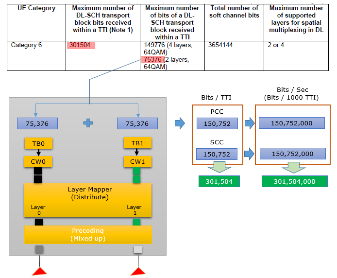
Each CC carries two transport blocks of 75,376 bits, one on each layer, so each CC gives 150,752 bits per TTI. Two CCs give 301,504 bits per TTI, which is exactly the Category 6 value (A). This is the relation (A) = (B) x N with N = 4 layers in total.
Case 2 : 4x4 64 QAM
The same category can also be reached without carrier aggregation. One carrier with four layers replaces two carriers with two layers each, but the numbers do not come out exactly the same.
In this example, the category 6 throughput is achieved by single carrier that uses 4 x 4 MIMO as illustrated below.
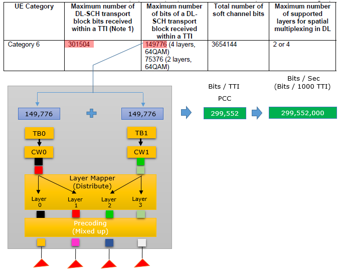
Here each transport block maps to two layers, so the UE reads the 4-layer value 149,776 bits. Two transport blocks give 299,552 bits per TTI. This is 1,952 bits below the Category 6 value of 301,504, because the 4-layer TBS is less than twice the 2-layer TBS. So a single 4x4 carrier stays below the category maximum.
Two 2x2 CCs reach the value exactly : 2 x 2 x 75,376 = 301,504 bits per TTI.One 4x4 carrier falls 1,952 bits short : the 4-layer TBS of 149,776 bits is smaller than 2 x 75,376.Both cases use four layers : the difference comes only from how the TBS table maps two layers into one transport block.
Category 9
Maximum Throughput for Category 9 is 452,256,000 bits (around 450 Mbps) and this can be implemented in a couple of different ways as shown in the follows examples.
Case 1 : 3CC CA - 2x2 64 QAM + 2x2 64 QAM + 2x2 64 QAM
Three 2x2 carriers at 64QAM reach the Category 9 value exactly. This is Category 6 Case 1 with one more CC, and each CC again gives 2 x 75,376 = 150,752 bits per TTI.
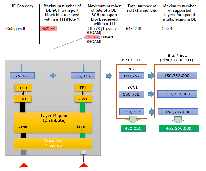
Three CCs give 3 x 150,752 = 452,256 bits per TTI, or 452,256,000 bits per second. This is the Category 9 value (A) with N = 6 layers.
Case 2 : 2CC CA - 4x4 64 QAM + 2x2 64 QAM
This case mixes antenna configurations. One CC runs 4x4 MIMO and the other runs 2x2 MIMO, both at 64QAM, so the diagram shows the two eNB structures side by side.
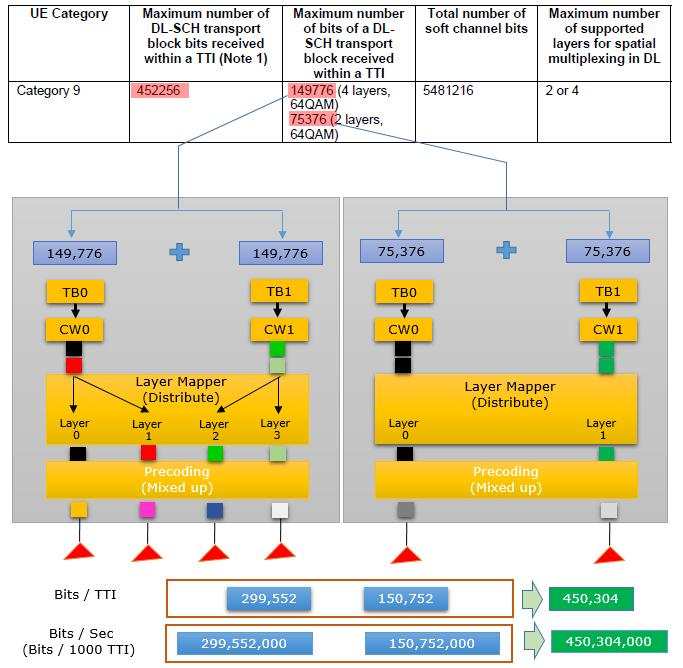
The 4x4 CC gives 2 x 149,776 = 299,552 bits and the 2x2 CC gives 150,752 bits per TTI. The sum is 450,304 bits, 1,952 bits below the Category 9 value, for the same reason as in Category 6 Case 2.
Three 2x2 CCs reach the value exactly : 3 x 150,752 = 452,256 bits per TTI.A 4x4 CC plus a 2x2 CC gives 450,304 bits : the 4-layer TBS again costs 1,952 bits against two 2-layer carriers.Category 9 is signalled in ue-Category-v1170 : together with Category 10, which has the same DL values.
Category 11
Maximum Throughput for Category 11 is 603,008,000 bits (around 600 Mbps) and this can be implemented in many different ways. Some examples of the possible configuration are shown in the follows examples.
Case 1 : 4CC CA - 2x2 64 QAM + 2x2 64 QAM + 2x2 64 QAM + 2x2 64 QAM
Four 2x2 carriers at 64QAM fill the Category 11 value exactly. This is Category 9 Case 1 with one more CC, and each CC again gives 150,752 bits per TTI.
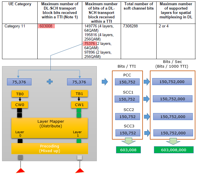
Four CCs give 4 x 150,752 = 603,008 bits per TTI, which is the Category 11 value (A).
Case 2 : 3CC CA - 2x2 256 QAM + 2x2 256 QAM + 2x2 256 QAM
256QAM raises the TBS per layer, so fewer carriers are needed. With 256QAM, each 2x2 transport block carries 97,896 bits instead of 75,376 bits, and this case uses three CCs.
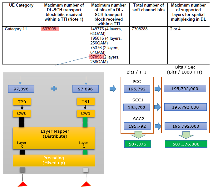
Each CC gives 2 x 97,896 = 195,792 bits per TTI, and three CCs give 587,376 bits. A fourth 256QAM CC would need 783,168 bits per TTI, which is more than a Category 11 UE supports.
Case 3 : 2CC CA - 4x4 64 QAM + 4x4 64 QAM
Two 4x4 carriers at 64QAM give four layers per CC and eight layers in total. Each transport block spans two layers, so the UE uses the 4-layer value of 149,776 bits.
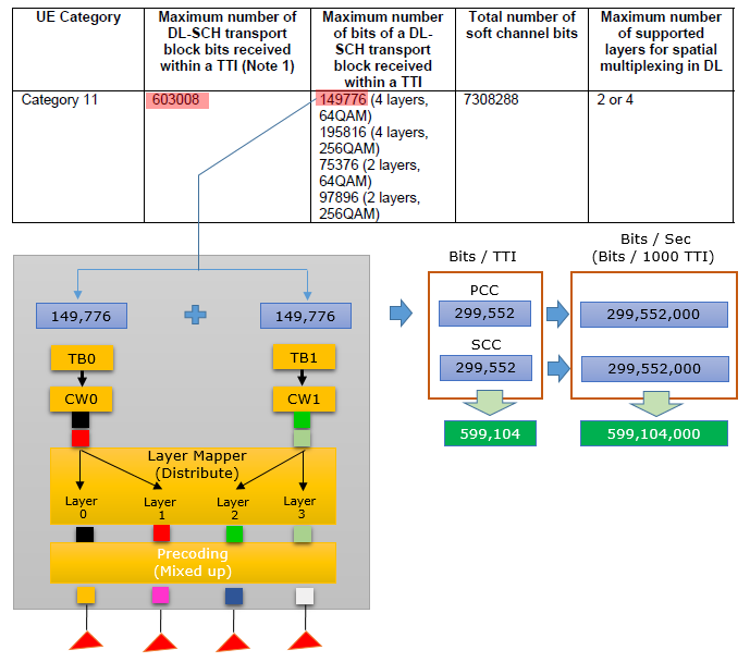
Each CC gives 299,552 bits per TTI, so two CCs give 599,104 bits per TTI. This is 3,904 bits below 603,008.
Case 4 : 2CC CA - 4x4 256 QAM + 2x2 256 QAM
Here 256QAM and mixed MIMO come together. One CC runs 4x4 with 195,816 bits per transport block, and the other runs 2x2 with 97,896 bits per transport block.
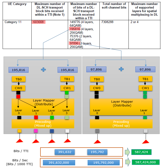
The 4x4 CC gives 391,632 bits and the 2x2 CC gives 195,792 bits per TTI. The total is 587,424 bits per TTI.
256QAM is what separates Category 11 from Category 9 : the 256QAM TBS values 97,896 and 195,816 appear for the first time.Only the 4CC 64QAM case hits 603,008 exactly : the 256QAM and 4x4 cases stay a little below it.Category 11 is signalled in ue-Category-v11a0 : the same field carries Category 12.
Category 12
Maximum Throughput for Category 12 is 603,008,000 bits (around 600 Mbps) and this can be implemented in many different ways. Some examples of the possible configuration are shown in the follows examples. Basically the throughput and transport block size at this layer for Category 12 is same as Category 11. The differences between Category 11 and 12 for Downlink lies in the layer higher than PHY/MAC and Uplink PHY/MAC throughput(See 36.306-Table 4.1-2 for Uplink Throughput).
For the UL, 36.306 Table 4.1-2 gives Category 11 51,024 bits per TTI and Category 12 102,048 bits per TTI. The total layer 2 buffer is also larger, 6,700,000 bytes for Category 12 against 6,200,000 bytes for Category 11. So the DL cases below are the same as for Category 11.
Case 1 : 4CC CA - 2x2 64 QAM + 2x2 64 QAM + 2x2 64 QAM + 2x2 64 QAM
The four Category 12 cases repeat the four Category 11 cases, because the two categories share the same DL values. Only the category name in the diagrams changes, and the per-CC arithmetic stays the same.
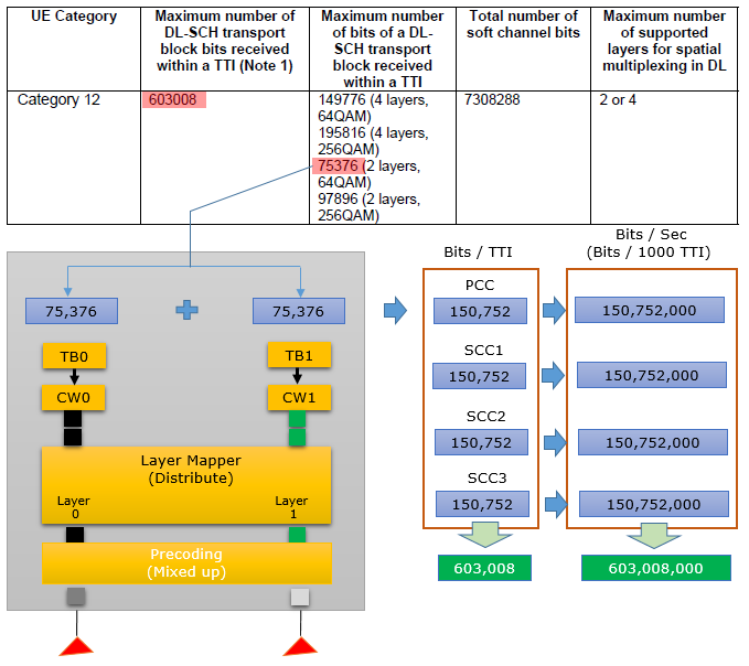
Four CCs of 150,752 bits give 603,008 bits per TTI, the Category 12 value (A).
Case 2 : 3CC CA - 2x2 256 QAM + 2x2 256 QAM + 2x2 256 QAM
Three 2x2 carriers at 256QAM carry 97,896 bits per transport block. This is the same combination as Category 11 Case 2, and it stays below the category value.

Three CCs of 195,792 bits give 587,376 bits per TTI.
Case 3 : 2CC CA - 4x4 64 QAM + 4x4 64 QAM
Two 4x4 carriers at 64QAM use the 4-layer value of 149,776 bits per transport block. This is the same combination as Category 11 Case 3.
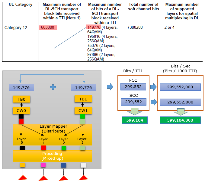
Two CCs of 299,552 bits give 599,104 bits per TTI.
Case 4 : 2CC CA - 4x4 256 QAM + 2x2 256 QAM
One 4x4 carrier and one 2x2 carrier, both at 256QAM, repeat Category 11 Case 4. The 4x4 CC carries 195,816 bits per transport block and the 2x2 CC carries 97,896 bits.
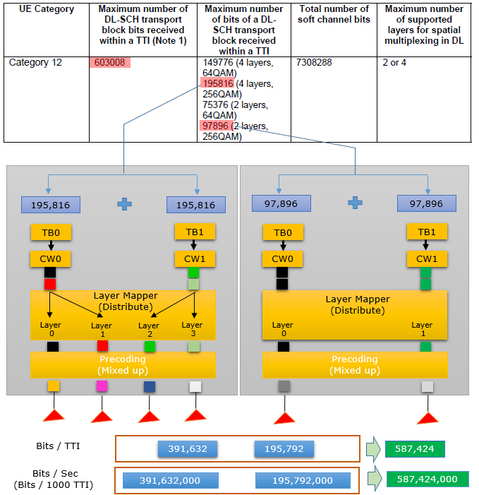
391,632 + 195,792 = 587,424 bits per TTI.
The DL numbers are the same as Category 11 : all four cases give the same totals.The difference is in the UL and the layer 2 buffer : 102,048 against 51,024 UL bits per TTI, and a larger buffer.
Category 15
Maximum Throughput for Category 15 ranges from 749,856,000 to 807,744,000 bits (around 800 Mbps) and this can be implemented in many different ways. Some examples of the possible configuration are shown in the follows examples.
From Category 15 on, 36.306 gives the maximum as a range. The UE takes the value in the range that its CA band combinations, MIMO and modulation can reach (Note 3 of Table 4.1A-1). If its capability goes beyond the range, the UE supports the upper bound. The tables drawn in the diagrams below come from an older version of 36.306. They show 749856-798800, while the current v19.3.0 range is 749,856 to 807,744 bits per TTI.
Case 1 : 4CC CA - 2x2 256 QAM + 2x2 256 QAM + 2x2 256 QAM + 2x2 256 QAM
Four 2x2 carriers at 256QAM make the simplest Category 15 case. Each CC gives 2 x 97,896 = 195,792 bits per TTI, as in Category 11 Case 2.
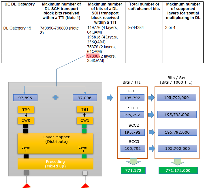
Four CCs give 4 x 195,792 = 783,168 bits per TTI, inside the Category 15 range. The green total boxes in the diagram show 771,172 and 771,172,000. The four CC boxes above them add up to 783,168, so read the totals as 783,168 bits per TTI and 783,168,000 bits per second.
Case 2 : 3CC CA - 4x4 256 QAM + 2x2 256 QAM + 2x2 256 QAM
One 4x4 carrier and two 2x2 carriers, all at 256QAM, give a second way to reach the Category 15 range. The per-CC sums are in a separate drawing below the eNB diagram.
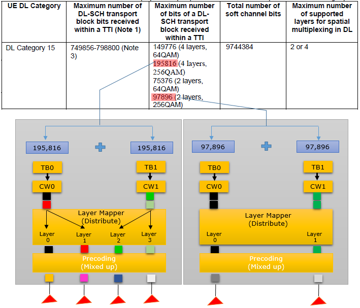
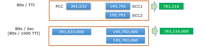
The 4x4 PCC gives 391,632 bits and each 2x2 SCC gives 195,792 bits per TTI. The total is 391,632 + 2 x 195,792 = 783,216 bits per TTI, again inside the range.
The maximum is now a range : the UE supports the value its own CA, MIMO and modulation capability reach inside the range.Four 256QAM 2x2 CCs give 783,168 bits per TTI : the total drawn as 771,172 in the diagram is a typo.Category 15 is signalled in ue-CategoryDL-v1260 : together with Category 16.
Category 16
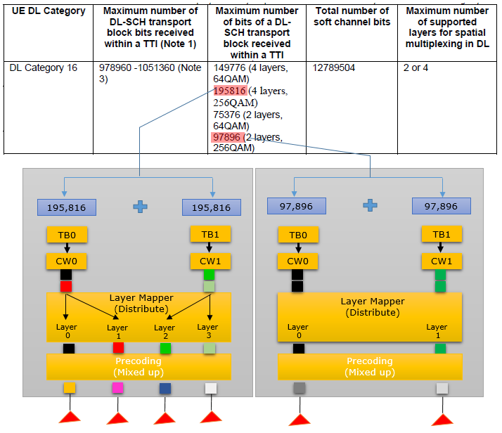
Maximum Throughput for Category 16 ranges from 978,960,000 (around 980 Mbps) to 1,051,360,000 bits (around 1 Gbps) and this can be implemented in many different ways. Some examples of the possible configuration are shown in the follows examples.
Case 1 : 5CC CA - 2x2 256 QAM + 2x2 256 QAM + 2x2 256 QAM + 2x2 256 QAM + 2x2 256 QAM
Five 2x2 carriers at 256QAM reach the bottom of the Category 16 range. Each CC gives 195,792 bits per TTI, the same value as in the Category 15 cases above.
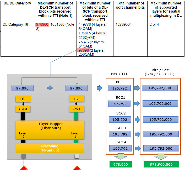
Five CCs give 5 x 195,792 = 978,960 bits per TTI, which is exactly the lower bound of the Category 16 range.
Case 2 : 3CC CA - 4x4 256 QAM + 4x4 256 QAM + 2x2 256 QAM
Two 4x4 carriers and one 2x2 carrier, all at 256QAM, give a slightly higher total with fewer CCs. The per-CC sums are in a separate drawing below the eNB diagram.
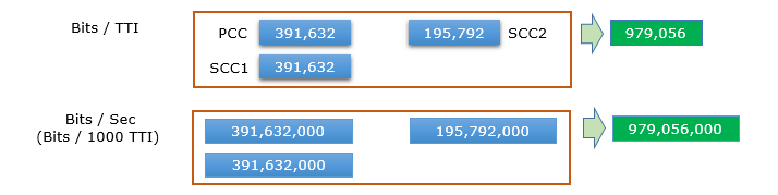
Each 4x4 CC gives 391,632 bits and the 2x2 CC gives 195,792 bits per TTI. The total is 2 x 391,632 + 195,792 = 979,056 bits per TTI.
Five 256QAM 2x2 CCs give the lower bound : 5 x 195,792 = 978,960 bits per TTI.Mixing 4x4 and 2x2 CCs needs fewer carriers : three CCs give 979,056 bits per TTI.
Category 18
Maximum Throughput for Category 18 ranges from 1,174,752,000 to 1,211,616,000 bits (around 1.2 Gbps) and this can be implemented in many different ways. Some examples of the possible configuration are shown in the follows examples.
The upper bound of 1,211,616 bits per TTI is from 36.306 v19.3.0. The tables drawn in the diagrams below come from an older draft. They show 1174752-1206016 and write the layer column as 2 or 4 [or 8], where the current table says 2 or 4 or 8.
Case 1 : 4CC CA - 4x4 64 QAM + 4x4 64 QAM + 4x4 64 QAM + 4x4 64 QAM
Four 4x4 carriers at 64QAM give 16 layers in total, with no 256QAM at all. Each transport block spans two layers and carries the 4-layer value of 149,776 bits.
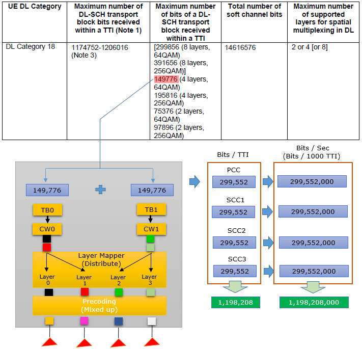
Each CC gives 299,552 bits per TTI, and four CCs give 1,198,208 bits per TTI, inside the Category 18 range.
Case 2 : 5CC CA - 4x4 64 QAM + 4x4 64 QAM + 2x2 256 QAM + 2x2 256 QAM + 2x2 256 QAM
This case combines two 4x4 carriers at 64QAM with three 2x2 carriers at 256QAM. The per-CC sums are in a separate drawing below the eNB diagram.
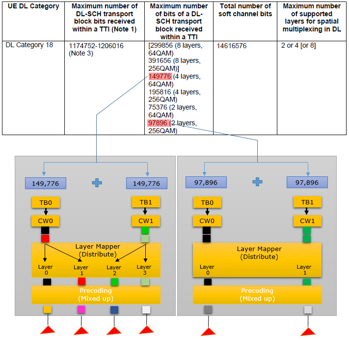
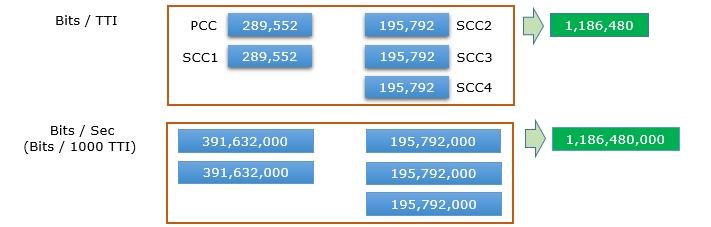
The two 4x4 CCs give 299,552 bits each, and the three 2x2 CCs give 195,792 bits each. The total is 2 x 299,552 + 3 x 195,792 = 1,186,480 bits per TTI, which matches the green boxes. Four other boxes in the lower drawing are typos. The PCC and SCC1 boxes show 289,552 instead of 299,552, and the two bits/sec boxes beside them show 391,632,000 instead of 299,552,000.
Case 3 : 6CC CA - 2x2 256 QAM + 2x2 256 QAM + 2x2 256 QAM + 2x2 256 QAM + 2x2 256 QAM + 2x2 256 QAM
Six 2x2 carriers at 256QAM reach the lower bound of the Category 18 range. The diagram labels each transport block with the 2-layer value of 97,896 bits.
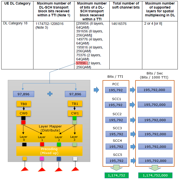
Six CCs give 6 x 195,792 = 1,174,752 bits per TTI, exactly the lower bound. Each CC here is a 2x2 carrier, so each transport block maps to one layer. The layer mapper in the diagram is drawn with four layers, as in the 4x4 cases, and that part of the drawing does not match the 97,896 bit label.
Six 256QAM 2x2 CCs give the lower bound : 6 x 195,792 = 1,174,752 bits per TTI.Four 4x4 64QAM CCs give 1,198,208 bits per TTI : 16 layers at 64QAM stay inside the range.Category 18 is signalled in ue-CategoryDL-v1330 : together with Category 19.
Category 19
Maximum Throughput for Category 19 ranges from 1,566,336,000 (around 1.55 Gbps) to 1,658,272,000 bits (around 1.65 Gbps) and this can be implemented in many different ways. Some examples of the possible configuration are shown in the follows examples.
Case 1 : 4CC CA - 4x4 256 QAM + 4x4 256 QAM + 4x4 256 QAM + 4x4 256 QAM without alternativeTBS-Index-r14
Four 4x4 carriers at 256QAM, without alternativeTBS-Index-r14, give the lower end of Category 19. Each transport block carries the 4-layer 256QAM value of 195,816 bits.
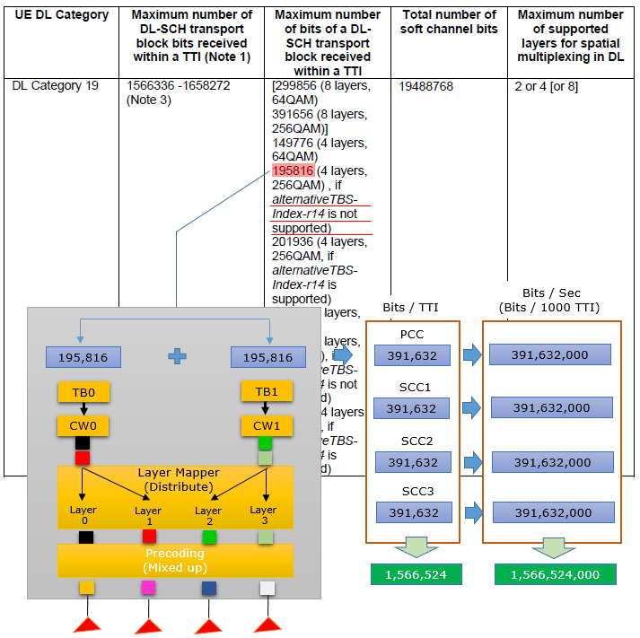
Each CC gives 391,632 bits per TTI, and four CCs give 4 x 391,632 = 1,566,528 bits per TTI. The green boxes show 1,566,524, which is 4 bits short, so read them as 1,566,528. This value is inside the Category 19 range, which starts at 1,566,336.
Case 2 : 4CC CA - 4x4 256 QAM + 4x4 256 QAM + 4x4 256 QAM + 4x4 256 QAM with alternativeTBS-Index-r14
alternativeTBS-Index-r14 is a UE capability for the alternative TBS index I_TBS 33B in 36.213. It gives a larger TBS at 256QAM, so each 4-layer transport block carries 201,936 bits instead of 195,816.
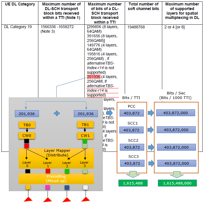
Each CC gives 403,872 bits per TTI, and four CCs give 1,615,488 bits per TTI. So the alternative TBS adds about 3 percent to the same carrier combination.
alternativeTBS-Index-r14 adds about 3 percent : 201,936 instead of 195,816 bits per 4-layer transport block.Four 4x4 256QAM CCs give 1,566,528 or 1,615,488 bits per TTI : the first value is drawn as 1,566,524 in the diagram.
Category 20
Maximum Throughput for Category 20 ranges from 1,948,064,000 (just a little below 2 Gbps) to 2,019,360,000 bits (around 2 Gbps) and this can be implemented in many different ways. Some examples of the possible configuration are shown in the follows examples.
The current 36.306 table for Category 20 also lists 1024QAM values, which the diagrams below do not show. These are 125,808 bits for 2 layers, 251,640 bits for 4 layers and 502,624 bits for 8 layers. The section after Category 20 uses them.
Case 1 : 5CC CA - 4x4 256 QAM + 4x4 256 QAM + 4x4 256 QAM + 4x4 256 QAM + 4x4 256 QAM without alternativeTBS-Index-r14
Five 4x4 carriers at 256QAM, without alternativeTBS-Index-r14, give a value near the lower end of Category 20. Each CC again gives 391,632 bits per TTI, as in Category 19 Case 1.
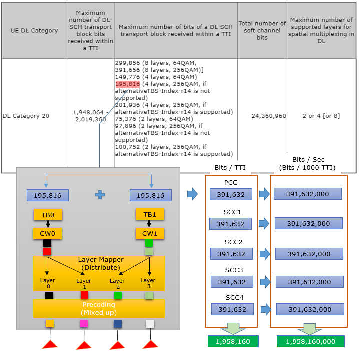
Five CCs give 5 x 391,632 = 1,958,160 bits per TTI. This is inside the Category 20 range, whose lower bound is 1,948,064.
Case 2 : 5CC CA - 4x4 256 QAM + 4x4 256 QAM + 4x4 256 QAM + 4x4 256 QAM + 4x4 256 QAM with alternativeTBS-Index-r14
The same five carriers with alternativeTBS-Index-r14 reach the top of the Category 20 range. Each 4-layer transport block now carries 201,936 bits instead of 195,816 bits, as in Category 19 Case 2.
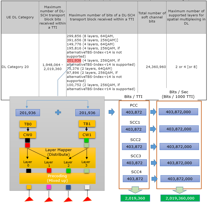
Five CCs give 5 x 403,872 = 2,019,360 bits per TTI. This is exactly the Category 20 upper bound, about 2 Gbps.
Five 4x4 256QAM CCs span the whole range : 1,958,160 bits without and 2,019,360 bits with alternativeTBS-Index-r14.The upper bound is 2,019,360 bits per TTI : this is the 2 Gbps LTE category.Category 20 is signalled in ue-CategoryDL-v1450 : and it is the first category with 1024QAM TBS values in its table.
Categories after Category 20
Category 20 is not the end of the LTE table. The current 36.306 v19.3.0 defines DL Categories 21 to 26, and most of them add 1024QAM. The method on this page still works for them, with the 1024QAM TBS values in column (B).
The 1024QAM entries are 125,808 bits for 2 layers, 251,640 bits for 4 layers and 502,624 bits for 8 layers. Category 21 does not list them, and its layers stay at 2 or 4. Categories 22 to 26 list them and allow 2, 4 or 8 layers. The table below gives the column (A) range of each category and the field that signals it.
DL Category | Max DL-SCH TB bits per TTI | 1024QAM TBS listed | Signalled in |
21 | 1,348,960 - 1,413,120 | No | ue-CategoryDL-v1460 |
22 | 2,349,504 - 2,562,784 | Yes | ue-CategoryDL-v1530 |
23 | 2,695,968 - 2,869,920 | Yes | ue-CategoryDL-v1530 |
24 | 2,936,880 - 3,028,608 | Yes | ue-CategoryDL-v1530 |
25 | 3,132,672 - 3,316,544 | Yes | ue-CategoryDL-v1530 |
26 | 3,422,400 - 3,531,888 | Yes | ue-CategoryDL-v1530 |
Let's try one example with the same method. Five 4x4 carriers at 1024QAM give 2 x 251,640 = 503,280 bits per CC per TTI. Five CCs give 2,516,400 bits per TTI, about 2.5 Gbps, which is inside the Category 22 range. The UE also has to support 1024QAM on each of those carriers, and the network has to schedule 1024QAM on them.
Categories 21 to 26 extend the same table : the per-CC arithmetic does not change.1024QAM adds a new column (B) value per layer count : 125,808, 251,640 and 502,624 bits for 2, 4 and 8 layers.Category 21 has no 1024QAM entries : its highest values are the 256QAM ones with alternativeTBS-Index-r14.
Reference
- 3GPP TS 36.306 v19.3.0 - Table 4.1-1, Table 4.1-2, Table 4.1-3 and Table 4.1A-1 with Note 3
- 3GPP TS 36.213 v19.4.0 - clause 7.1.7, Table 7.1.7.2.1-1 and Table 7.1.7.2.2-1
- 3GPP TS 36.331 v19.3.0 - UE-EUTRA-Capability, ue-Category and ue-CategoryDL fields, alternativeTBS-Index-r14