If you have looked into Physical layer of LTE-NB, you might have felt that LTE-NB looks a pretty much new design. It is true. There are huge difference between legacy LTE and LTE-NB in Physical layer even though you still see the same terminology being used in both technology (e.g, Resource Elemenent, Sub Carrier Spacing, Radio Frame, Sub Frame etc). However, the difference does not stay in physical layer only. There are pretty big modification on core network side as well.
Overall network architecture of LTE-NB can be illustrated as below. You would notice that the network components of LTE-NB are almost same as in legacy LTE. It is understandable. No Network Operator would like to deploy a completely new core network for LTE-NB. You may notice only one new component labeled SCEF. I see this from Rel 13 of 23.682 and 23.401. Since this is pretty new components as of now(May 2017), I am not sure how soon we will see this deployed in real network.
In short, just looking at the following illustration, the biggest difference you would see would be that there are not a single path for the user data, there are multiple options for it. It can take the solid BLUE path and this is same as legacy LTE data path. This operation mode that is using this path is called 'UP-Mode'. The RED paths are the new path designed for LTE-NB. The operation mode that are using these path is called 'CP-Mode'.

The blue line is the UP-Mode path through the S-GW and P-GW. The dashed red line is CP-Mode IP data, from the MME through the S-GW and P-GW. The solid red line is CP-Mode Non-IP data, from the MME through the SCEF.
Blue, UP-Mode : eNodeB, S-GW, P-GW and the application server, as in legacy LTE.Dashed red, CP-Mode IP data : the user data enters the core at the MME, then follows the S-GW and P-GW.Solid red, CP-Mode Non-IP data : the MME hands the data to the SCEF, which passes it to the application server.SCEF is the only new node : every other box in the picture exists in legacy LTE.
Followings are the topics to be covered in this page.
- UP-Mode vs CP-Mode
- UP Mode : IP-Data
- CP Mode : Non-IP Data
- CP Mode : IP Data
- UE Capabability for CIoT Optimization
- Network Capability for CIoT Optimization
- Reference
UP-Mode vs CP-Mode
As you see in the illustration shown above, there are three different options for the user data in LTE NB. It can take the solid BLUE path and this is same as legacy LTE data path. This operation mode that is using this path is called 'UP-Mode'. The RED paths are the new path designed for LTE-NB. The operation mode that are using these path is called 'CP-Mode'.
The 'CP-Mode' is the new path defined in LTE-NB. As you see in the diagram, the most critical difference between UP and CP mode is that the user data go through MME in CP mode.
As you know, the main role of MME in LTE is to process the signaling message (RRC / NAS message). Does it imply that in CP-Mode, the user data is carried by signaling messages ? Good guess ! Yes, the user data is carried by some signaling messages in CP-mode. More specifically, the user data is carried by NAS message. Even more specifically, the data is carried by NAS message which the RRC message carries in its 'dedicatedInfoNAS' IE.
23.401 v20.0.0 names the two modes the User Plane CIoT EPS Optimisation and the Control Plane CIoT EPS Optimisation. Clause 5.3.4B.1 describes the control plane one. The UE and the MME transfer data in NAS PDUs that include the EPS Bearer Identity of the PDN connection, and no S1-U bearer is established. The data uses the NAS transport of RRC and S1-AP, then GTP-U tunnels from the MME to the S-GW and from the S-GW to the P-GW. For a Non-IP connection through the SCEF, the data goes from the MME to the SCEF instead.
For IP data in CP-Mode, the UE and the MME may also apply ROHC header compression. The UE compresses uplink IP headers and the MME decompresses them, and the MME compresses downlink headers for the UE. The configuration is set up during PDN connection establishment.
CP-Mode : Control Plane CIoT EPS Optimisation: data inside NAS PDUs, through the MME.UP-Mode : User Plane CIoT EPS Optimisation: data on S1-U, as in legacy LTE.The EPS Bearer Identity travels with the data : it tells the MME which PDN connection each NAS PDU belongs to.Header compression is between the UE and the MME : the eNodeB only relays the NAS PDU.
UP Mode : IP-Data
UP-Mode carries IP data on the same path as legacy LTE: a data radio bearer to the eNodeB, then S1-U to the S-GW and P-GW. So the question for UP-Mode is not the path, but what makes it cheaper for a device that sends a few bytes and then sleeps.
The answer in 23.401 v20.0.0 is the Connection Suspend and Connection Resume procedures of clauses 5.3.4A and 5.3.5A. When the eNodeB suspends the connection, the MME enters ECM-IDLE. The S1AP association, the UE context and the bearer context stay stored in the eNodeB, the UE and the MME. The next time the UE has data, it resumes the connection instead of setting up a new one. So it does not repeat the security setup and the bearer setup.
Resume needs AS security, because RRCConnectionResume-NB and RRCConnectionResumeComplete-NB are sent only on SRB1, as the SRB mapping page shows. A UE that supports only CP-Mode therefore never uses this procedure. Clause 4.3.5.10 adds one more rule: a UE that indicates support of the User Plane CIoT EPS Optimisation shall also indicate support of S1-U data transfer.
Same path as legacy LTE : data radio bearer, S1-U, S-GW and P-GW.Suspend keeps the context : the eNodeB, the UE and the MME all store it while the UE is idle.Resume replaces a new setup : the UE skips security and bearer setup on the next transmission.UP CIoT implies S1-U support : the UE must indicate both.
CP Mode : Non-IP Data
Many IoT devices send a few bytes of sensor data, and an IP header can be larger than the data itself. Non-IP data avoids the header entirely, but then the network needs another way to find the application server. 23.401 v20.0.0 clause 4.3.17.8 describes how it does that.
The UE asks for a PDN connection of PDN type Non-IP, in the Attach Request or in a PDN Connectivity Request. At each request, the MME decides between two delivery mechanisms, based on an indication associated with the APN. With SCEF based delivery, the MME sets up a PDN connection towards the SCEF, and the APN is an FQDN that resolves to the SCEF. With SGi based delivery, the P-GW passes the data to the application server through a point-to-point tunnel, for example UDP/IP encapsulation.
The two mechanisms differ in who can use them. SCEF based delivery applies only to the Control Plane CIoT EPS Optimisation, which is the solid red path in the picture at the top of this page. SGi based delivery can be used by any UE, independently of either optimisation. In both cases, dedicated bearers are not supported for Non-IP data, and in-sequence delivery is not guaranteed unless the Reliable Data Service of 23.682 is used.
PDN type Non-IP : the UE requests it in the ESM connection request.SCEF based delivery : only with the Control Plane CIoT EPS Optimisation.SGi based delivery : through the P-GW with point-to-point tunnelling, for any UE.No dedicated bearers : Non-IP data uses the default bearer only.
CP Mode : IP Data
IP data can also take the control plane. The UE puts the IP packet into a NAS PDU, and the MME forwards it over GTP-U to the S-GW and P-GW. That is the dashed red path at the top of this page. The two figures below come from 23.401 clause 5.3.4B, one for each direction.
< 23.401-Figure 5.3.4B.2-1: MO Data transport in NAS PDU >


The uplink data rides in the NAS PDU of the RRC connection establishment. The MME checks integrity, decrypts the data and forwards it to the S-GW and P-GW.
Steps 1 and 2 carry the data : the NAS Data PDU with EBI goes in the RRC connection establishment and in the S1-AP Initial UE Message.Step 1b is NB-IoT specific : the eNodeB may retrieve the UE context from the MME.Step 3 is NAS security : the MME checks integrity and decrypts, not the eNodeB.Steps 9 to 13 return downlink data : the MME encrypts it and sends it back inside a NAS PDU.
23.401 v20.0.0 adds one option to step 1. The UE may send the NAS PDU in RRCEarlyDataRequest instead of a full RRC connection establishment. The eNodeB then marks the S1-AP Initial UE Message with the EDT Session indication.
< 23.401-Figure 5.3.4B.3-1: MT Data transport in NAS PDUs >


Downlink data first triggers paging. The UE answers with a NAS Control Plane Service Request, and the data then reaches it inside a NAS PDU.
Steps 1 to 4 find the UE : Downlink Data Notification from the S-GW, then paging.Step 5 uses a Control Plane Service Request : not the Service Request of legacy LTE.Steps 12 to 14 deliver the data : encrypted by the MME and carried in an RRC DL message.Steps 16 to 19 carry uplink data : the UE sends it in the same connection, before the release in step 21.
UE Capabability for CIoT Optimization
The UE declares which optimisations it supports in the UE network capability IE of the Attach Request. The screenshot below shows octet 7 of that IE, which holds the CIoT flags.

In this capture every CIoT flag is not supported, so the UE uses neither optimisation and attaches like a legacy LTE UE.
CP CIoT : Control-plane CIoT EPS optimization.UP CIoT : User-plane CIoT EPS optimization.S1-U data : data transfer that is not subject to CIoT optimisations.HC-CP CIoT and ERw/oPDN : header compression for CP-Mode, and EMM-REGISTERED without a PDN connection.
23.401 v20.0.0 clause 4.3.5.10 calls this information the Preferred Network Behaviour. Besides the support flags, it tells the network whether the UE prefers the control plane or the user plane optimisation. The capture on the Full Stack Protocol Sequence page shows the opposite case to the screenshot above: a UE that supports Control plane CIoT EPS optimization and prefers it.
In that capture the preference is not in UE network capability. It sits in the Additional update type IE of the same Attach Request, where Preferred CIoT network behaviour is set to Control-plane CIoT EPS optimization. The same capture sets S1-U data transfer, User plane CIoT and header compression to not supported, so this UE can send data only through the MME.
Network Capability for CIoT Optimization
The network answers with the EPS network feature support IE in the Attach Accept. The screenshot below shows octets 3 and 4, which carry the same CIoT flags from the network side.
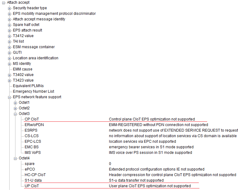
This network supports neither CIoT optimisation, but it does support IMS voice over PS and emergency bearer services, which is a typical legacy LTE network.
CP CIoT in octet 3 : Control plane CIoT EPS optimization support.UP CIoT, S1-U data and HC-CP CIoT in octet 4 : the other CIoT related flags.The network decides : the UE uses an optimisation only when both sides support it.
23.401 v20.0.0 clause 4.3.5.10 calls this the Supported Network Behaviour, and the MME indicates it per TAI list. The MME may indicate support of the Control Plane and the User Plane CIoT EPS Optimisation, and of S1-U data transfer. It may also indicate SMS transfer without Combined Attach, and Attach without PDN connectivity.
The Attach Accept on the Full Stack Protocol Sequence page shows a network that does support CP-Mode. Its EPS network feature support sets Control plane CIoT EPS optimization and EMM-REGISTERED without PDN connectivity to supported. User plane CIoT and header compression for CP-Mode are not supported. That network therefore matches the UE in the same capture, and user data can travel only inside NAS messages.
Reference
[1] 3GPP 23.401 - LTE;General Packet Radio Service (GPRS) enhancements for Evolved Universal Terrestrial Radio Access Network (E-UTRAN) access
5.3.4B Data Transport in Control Plane CIoT EPS optimisation
[2] 3GPP 23.682 - Architecture enhancements to facilitat communications with packet data networks and applications
[3] 1MA266: Narrowband Internet of Things (Rhode&Schwarz)
[4] Cellular-IoT – Part 7 – To IP or Not to IP – That is the Question!
[5] 3GPP SCEF PRIMER
[6] 3GPP TS 23.401 v20.0.0 - clause 4.3.5.10, 4.3.17.8, 5.3.4A, 5.3.4B and 5.3.5A