With the introduction of mobile device and mobile network, one thing a lot of mobile users wanted to have was "I want to see TV (Movies etc on my mobile phone.". A set of first solutions to this requirement was DVB-H/DVB-T, DMB, ISDB-T, MediaFLO etc. These technlogies are still very widely used in some contries. There are many mobile device supporting both normal mobile phone capability and the mobile TV reception functionality. So for the users point of view, it was very good since they can have both mobile phone and TV on a single device with a small extra cost. But for the service provider's point of view, it is not that simple story. Mobile phone network and mobile TV network is totally different and separate. So it would be pretty big investment to deploy the network for mobile TV.
Then many people start having another idea saying "Why don't we prvide this kind of mobile TV (Broadcasting/Multicasting) service through the existing mobile phone network/technology ?".
The intial implementation of this idea was MBMS (Multimedia Broadcast Multicast Services) in UMTS and its LTE counter part is MBSFN (Multimedia Broadcast Single Frequency network or Multicase Broadcast Single Frequency Network).
Overall concept is as follows. A eNodeB can transmit the same data (idential data) to multiple UE simulteneously. In some case, multiple eNodeB can transmit the identical data simultaneously so that UE can receive the same data from multiple eNodeBs.
The picture below compares the two approaches. On the left, a dedicated broadcast network such as DVB-T/DVB-H, DMB or MediaFLO reaches the devices from its own towers. On the right, MBMS and MBSFN (eMBMS) reuse the base stations of the mobile network, and several cells send the same data to the same devices.

Mobile TV over a dedicated broadcast network, and as an overlay on the mobile network.
36.300 expands MBSFN as Multimedia Broadcast multicast service Single Frequency Network. MBMS is the service, and MBSFN is the way LTE transmits it. Cells send identical waveforms at the same time, so a UE sees them as one transmission and combines their energy. Release 13 added a second mode, SC-PTM, which sends MBMS in a single cell on the PDSCH. This page covers the MBSFN mode.
Followings are the topics to be covered in this page.
- eMBMS Implementation Overview
- Network Components for MBSFN eMBMS
- Session Start/Stop
- MBSFN Access Network Structure/Definition
- Radio Channels for MBSFN eMBMS
- MCCH Implementation Structure/ Information in MCCH
- MBSFN Signalling on BCCH
- MBSFN Signalling on MCCH
- MAC Implementation for MCH
- MBSFN Subframe Structure
- Multi-Cell Transmission
- Reference - 3GPP
- Reference - 3GPP Implementation
- Reference - 3GPP Test Specificaiton
- MBMS Servers
- Reference
eMBMS Implementation Overview
To implement eMBMS, we need to tweak (or implement new feature) across almost all layers from PHY to Core Network. Following shows some of key feature on each layer that need to be implemented on each layer. I would not explan the details on each of these items. The details will be described in following sections.
|
|
|

The changes that eMBMS brings to each layer. The links on the right lead to the section for each layer.
The picture follows the protocol stack from the bottom up. The PHY adds the MBSFN subframe, the MBSFN reference signal and the PMCH. MAC adds the MCH transport channel, its own LCID table and the MCH Scheduling Information MAC control element. RLC adds the MTCH and MCCH logical channels, and both use UM mode. RRC adds MBSFN fields to SIB2, SIB3 and SIB13 on BCCH, and the MBSFNAreaConfiguration message on MCCH.
The core network adds three entities: the MCE, the MBMS GW and the BM-SC. The picture writes them as MCE, MBGW and MB-SC, and 36.300 uses the names MBMS GW and BM-SC. The section below describes each of them and the interfaces between them.
PHY : MBSFN subframe, MBSFN reference signal and PMCH.MAC and RLC : MCH, MTCH and MCCH, with RLC in UM mode.RRC : SIB2, SIB3 and SIB13 on BCCH, and MBSFNAreaConfiguration on MCCH.
Network Components for MBSFN eMBMS
For implementing eMBMS, a couple of components are added in the core network side as shown below. MCE, MBSFN Gateway and BM-SC are those components. (Refer to 36.300 15.1.1 E-MBMS Logical Architecture for details).

E-MBMS entities added to the EPC. The MBSFN Gateway in the picture is the MBMS GW of 36.300, and M1, M2 and M3 are the new interfaces.
MCE (Multi-cell/multicast Coordination Entity) : This is a logical entity and, physically it can be integrated into another network element. It has following functionality,
- admission control and allocation of the radio resources for all eNB in the MBSFN area for multicell MBMS transmission.
- counting and acquisition of counting results for MBMS services.
- controlling resumption of MBMS session within MBSFN area
- controlling suspension of MBMS session within MBSFN area
- Involved in MBMS Session Control Signaling
- NOT perform UE-MCE signaling
MBMS Gateway(GW) : This is a logical entity and, physically it can be integrated into another network element. It has following functionality,
- Sending/broadcasting of MBMS packets to each eNB transmitting the service
- Uses IP multicast as the means of forwarding MBMS user data to the eNB
- Performs MBMS Session Control Signalling (Session start/update/stop) towards the E-UTRAN via MME
M3 interface : Interface between MME-MCE
- allows for MBMS Session Control Signaling on E-RAB level (e.g, MBMS Session Start/Stop)
- does not convey radio configuration data
- SCTP is used as signalling transport (e.g, Point-to-Point signaling)
M2 interface : Interface between MCE-eNB
- allows for MBMS Session Control Signaling and Radio Configuration data
- SCTP is used as signalling transport (e.g, Point-to-Point signaling)
M1 interface : Interface between MBMS GW-eNB
- purely a user plane interface
- No Control Plane Application Part is defined for this interface
- IP multicast is used for point-to-multipoint multipoint delivery of user packets
36.300 v19.2.0 clause 15.1.1 gives the MCE more functions than the list above. The MCE also decides whether a session uses MBSFN or SC-PTM, and whether time or frequency interleaving applies. The MCE can be a separate node, which is the centralized MCE architecture, or part of each eNB, which is the distributed MCE architecture. In both cases the M2 interface stays between the MCE and the eNB.
MCE : radio resources for the whole MBSFN area, and no signalling with the UE.MBMS GW : IP multicast of the user data to the eNBs over M1.M3 and M2 : control plane over SCTP. M1 is user plane only.
Session Start/Stop
How does an MBMS session reach the air? The EPC starts and stops each session through the MME, and the request travels over M3 to the MCE and over M2 to the eNBs. The diagrams below follow 36.300 clauses 15.7.1.1 and 15.7.1.2.
In Session Start, the MME sends MBMS Session Start Request to the MCE, and the MCE forwards it to the eNB. The MCE then sends MBMS Scheduling Information with the updated MCCH content, and the eNB joins the IP multicast group to receive the user data.

MBMS Session Start over M3 and M2. The eNB joins the IP multicast group before the synchronized user data starts.

MBMS Session Stop. The eNB leaves the IP multicast group after the MCCH is updated.
The UE side of both diagrams needs care. No RRC message named MBMS Session Start or MBMS Session Stop exists. For Session Start, the eNB sends an MCCH change notification on the PDCCH and then an updated MBSFNAreaConfiguration message. For Session Stop, the eNB removes the stopped session from the next MBSFNAreaConfiguration message. 36.300 does not send an RRC release to the UE for Session Stop. The E-RAB it releases is the MBMS bearer between the EPC and the eNB.
MME to MCE to eNB : Session Start and Session Stop over M3 and M2.MBMS Scheduling Information : the MCE gives the eNB the new MCCH content.UE side : MCCH change notification and an updated MBSFNAreaConfiguration.
MBSFN Access Network Structure/Definition
MBSFN needs cells that are time-synchronized and grouped. 3GPP defines several nested areas for this purpose. The two pictures below show how the areas relate, and the definitions after them come from 36.300 clause 15.0.

An MBSFN Service Area holds several MBSFN Areas. Reserved cells sit inside an area but do not join the MBSFN transmission, and one eNB can belong to several MBSFN Areas.

Two MBSFN Areas, A and B. The cells in the middle belong to both, and each UE receives the same synchronized data from every cell of its area.
Followings are common terminologies you need to understand in MBSFN/MBMS. (Based on 3GPP TS 36.300 Chapter 15)
MBSFN Synchronization Area : This refers to an area of the network where all eNodeBs can be synchronized and perform MBSFN transmissions.
- MBSFN Synchronization Area are capable of supporting one or more MBSFN Area
- One eNB can only belong to one MBSFN Synchronization Area on a given frequency layer.
- MBSFN Synchronization Area are independent from the definition from the definition of MBMS Service Area
MBSFN Transmission/Transmission in MBSFN mode : This refers to a simulcast transmission technique realized by transmission of identical waveforms at the same time from multiple cells. An MBSFN Transmission from multiple cells within the MBSFN Area is seen as a single transmission by a UE.
MBSFN Area : This is an area which consists of a group of cells within an MBSFN Synchronization Area, which are co-ordinated to achieve an MBSFN Transmission.
- Except for the MBSFN Area Reserved Cells, all cells within an MBSFN Area contribute to the MBSFN Transmission and advertise its availability.
- The UE many only need to consider a subset of the MBSFN areas that are configured, i.e when it knows which MBSFN area applies for the services it wants to recieve.
MBSFN Area Reserved Cell : This refers to a cell within a MBSFN Area which does not contribute to the MBSFN Transmission. These cells may transmit data for other services but it should not transmit it in too high power that may interfere other MBSFN cell. So it should control its transmission power very carefully.
Synchronization Sequence : This refer to a sequence of MBSFN service which has the same duration and start time which is configured in the BM-SC and the MCE. Each SYNC PDU contains a time stamp which indicates the start time of the synchronisation sequence.
Syncronizsation Period : This refer to a duration which multiple synchronized sequence maintain the synchronization. The synchronization period provies the time reference for the indication of the start time of each synchronisation sequence.
A cell can belong to at most 8 MBSFN Areas, which is maxMBSFN-Area in 36.331. SIB13 lists the areas of the cell, and each area has its own MCCH. The UE needs only the areas that carry the services it wants, so it can ignore the others.
MBSFN Synchronization Area : one per eNB on a given frequency.MBSFN Area : the cells that send one MBSFN transmission.Reserved cell : inside the area, but outside the MBSFN transmission.
Radio Channels for MBSFN eMBMS
LTE uses totally separate channel (logical cand transport channel) for MBSFN. As you may guess, it uses MCCH for control information and MTCH for data transmission. The information carried by MCCH includes subframe allocation and MCS(Modulation Coding Scheme).
RLC mode for MBSFN is UM (It is understandable since MBSFN is for broadcasting and there is no feedback from the reciever).
One or Several MTCH and one MCCH are multiplexed onto MCH by MAC layer.
MIMO is not defined for PMCH.

Channel mapping for MBSFN. MTCH and MCCH map onto the MCH and the PMCH, separate from the unicast channels.
The dark blue path in the picture is the MBSFN path. The MCH has no HARQ, because the UE sends no feedback, and every cell of the MBSFN area sends the same transport block in the same subframe. The PMCH uses antenna port 4, with a single antenna port and no precoding, which is why MIMO is not defined for it.
Release 13 added a second path for MBMS. SC-PTM maps SC-MCCH and SC-MTCH onto the DL-SCH and the PDSCH of one cell. That path is not in the picture, because it serves a single cell rather than an MBSFN area.
MTCH and MCCH on MCH : then on PMCH.RLC UM and no HARQ : the UE sends no feedback.SC-MTCH and SC-MCCH on DL-SCH : the SC-PTM path from Release 13.
MCCH Implementation Structure/ Information in MCCH
The MCCH tells the UE which services run in an MBSFN area and where each one sits on the MCH. It changes only at fixed boundaries, and the UE learns about a change in advance.
Following is the overall principles for MCCH implementation listed 36.300 15.3.5.
MCCH and MBSFN Area association
Each MBSFN area has exactly one MCCH, and the MCCH describes only that area. A UE interested in services from two areas therefore reads two MCCHs, one for each area.
- One MBSFN Area is associated with one MCCH and one MCCH corresponds to one MBSFN Area
- MCCH is transmitted by all cells within an MBSFN Area, except the MBSFN Area Reserved Cells
MCCH Transmission
The MCCH repeats within each modification period, so a UE that joins late can still read it. Its content can change only at the boundary of a modification period.
- MCCH is transmitted by all cells within an MBSFN Area, except the MBSFN Area Reserved Cells
- MCCH is transmitted by RRC every MCCH repetition period
- MCCH uses a modification period
Notification Mechanism
When MCCH gets modified due to either Session Start or presense of an MBMS counting request message, Network needs to inform UE of the modification. For this, network is using special notification mechanism summarized below.
- The notification is sent periodically throughout the modification period preceding the change of MCCH, in MBSFN subframes configured for notification.
- The DCI format 1C with M-RNTI is used for notification.
- This DCI has one field (8 bits) named 'MCCHChangeNotification' which indicate the one or more MBSFN Areas in which the MCCH changes.
UE side procedure
The rules below describe what the UE does with the notification. They come from the last three items of 36.300 clause 15.3.5, and 36.331 clause 5.8.1.3 gives the detailed procedure.
- The UE monitors more than one notification subframe per modification period
- When the UE recieves a notification, it acquires the MCCH at the next modification period boundary
- If a changes in MCCH is not announced by the notification mechanism, UE can still detect the changes by MCCH monitoring at the modification period.
The 8-bit field of DCI format 1C is called Information for MCCH change notification in 36.212. Each MBSFN area uses the bit at position notificationIndicator, which SIB13 gives for each area. MCCH also carries the MBMSCountingRequest message when the network counts interested UEs, and the same notification announces it.
One MCCH per MBSFN area : sent by every cell of the area except reserved cells.Change only at a modification period boundary : announced in the period before.DCI format 1C with M-RNTI : one bit per MBSFN area.
MBSFN Signalling on BCCH
The UE finds MBSFN through system information. SIB2 tells it which subframes are MBSFN subframes, SIB3 describes the neighbour cells, and SIB13 points to the MCCH of each MBSFN area. The summary below lists the principles, and the sub-sections show each SIB.
Following summary comes from 36.300 15.3.6 and further details follows the summary.
- BCCH only tell you where MCCH can be found, but does not tellyou whether any service is available now or not (SIB 2)
- For each MCCH, BCCH notifies UE of following informations (SIB 13)
- the scheduling of the MCCH for multi-cell transmission on MCH
- MCCH modification period, repetition period radio frame offset, subframe allocation
- an MCS which applies to the subframes indicated for MCCH scheduling and for the first subframe of all MSPs(MCH Scheduling Period) in that MBSFN Area
- For the notification commonly used for all MCCH (SIB 13)
- configures the position of the MCCH change notification subframe and the number of occasions monitored by the UE
- indicatesthe mapping between the PDCCH bit(s) carried in the notification and the MCCH(s)
MBSFN Subframe Configuration
Since the MBSFN data is carried by the same physical channel which is used for mobile comunication, we have to use carefull scheduling for MBSFN so that it would not interfer normal mobile communication. This physical layer scheduling is specified in SIB2 as shown below.

mbsfn-SubframeConfigList in SIB2, with radioframeAllocationPeriod n8, radioframeAllocationOffset 2 and a oneFrame bitmap.
Radio Frame meeting the following equation is allocated for MBSFN.
SFN mod radioframeAllocationPeriod = radioframeAllocationOffset
Subframes that is allocated for MBSFN within the MBSFN Frame is determined by a bitmap as shown below.

The FDD mapping of the oneFrame bitmap. Its six bits cover subframes 1, 2, 3, 6, 7 and 8, and subframes 0, 4, 5 and 9 are not available.
Following is an example of MBSFN SFN, Subframe allocation. Try with following parameters and See if you come out with the same result as mine.

With period 8 and offset 2, SFN 2, 10 and 18 carry MBSFN subframes. The bitmap 110000 selects subframes 1 and 2 of those frames.
Subframes 0, 4, 5 and 9 are left out because they carry the synchronization signals, the PBCH or paging. Release 14 added oneFrame-v1430 and fourFrames-v1430 in 36.331 v19.3.0 for the FeMBMS/Unicast-mixed cell. These fields extend the bitmap to subframes 4 and 9. Release 16 added oneFrame-v1610 and fourFrames-v1610, which cover subframes 0 and 5. The picture shows the Release 8 fields only.
SFN mod radioframeAllocationPeriod = radioframeAllocationOffset : selects the radio frames.oneFrame or fourFrames : selects subframes 1, 2, 3, 6, 7 and 8 in FDD.-v1430 and -v1610 extensions : add subframes 4, 9, 0 and 5 for FeMBMS.
MBSFN Neighbour Cell Configuration
A UE also needs to know whether its neighbour cells use MBSFN subframes. In an MBSFN subframe, a cell sends the CRS only in the non-MBSFN region, as 36.211 clause 6.10.1.2 states. SIB3 gives this information in neighCellConfig.

neighCellConfig in SIB3 and the meaning of its four values.
The value 01 tells the UE that no neighbour cell uses MBSFN subframes. The UE can then measure the CRS of neighbour cells in any subframe. With 00, some neighbour cells may use MBSFN subframes that the serving cell does not use. The UE then cannot count on the neighbour CRS in every subframe.
MBSFN Control Channel Information
As I explained above, MBSFN is using two different channel : MCCH and MTCH. As you may easily guess, MTCH carry the MBMS traffic data and MCCH is for conveying the control message. You learned that the MBSFN physical frame and broadcasting cycle is defined in SIB2, but there is no MBSFN control channel information in SIB2. To carry the MBSFN control channel information, 3GPP defined a separate SIB : SIB13 and major component of SIB13 is as shown below.
MBSFN control channel information and MBSFN Area specification is specified by SIB13 as shown below.
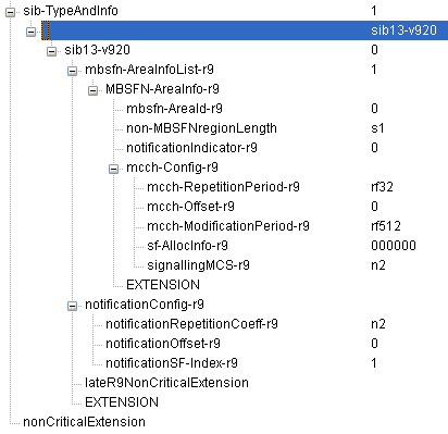
SIB13 with one MBSFN area, its MCCH configuration and the notification configuration.

mcch-RepetitionPeriod rf128 with mcch-Offset 5 inside mcch-ModificationPeriod rf512. The drawing shows three repetitions per period, while 512 / 128 gives four.
The MCCH appears in radio frames where SFN mod mcch-RepetitionPeriod = mcch-Offset, and sf-AllocInfo selects the subframes in those frames. The field signallingMCS sets the MCS of those subframes. Release 14 added mcch-Config-r14 in 36.331 v19.3.0 with shorter periods: rf1 to rf16 for the repetition period and rf1 to rf256 for the modification period. SIB13 also gained mbsfn-AreaInfoList-r16 and mbsfn-AreaInfoList-r17 for later MBMS enhancements.
SIB2 : which subframes are MBSFN subframes.SIB3 : whether neighbour cells use MBSFN subframes.SIB13 : where the MCCH of each MBSFN area is, and how notification works.
MBSFN Signalling on MCCH
When does the UE read the MCCH? The MCCH repeats within each modification period and changes only at period boundaries, so the UE reads it only when a trigger tells it to.
There are several triggers that let UE aquire MCCH message which is summarized as below. (Refer to 36.331 5.8.2.3 for further information)

The three triggers for MCCH acquisition in 36.331 clause 5.8.2.2.
Once any one of the trigger is set, UE have to aquire MCCH and decode following informations. (Refer to 36.331 6.2.2, 6.3.7)

MBSFNAreaConfiguration with one common subframe allocation, one PMCH and one MBMS session, with the value range of each field.
commonSF-Alloc : It indicates the subframes allocated to the MBSFN area
commonSF-AllocPeriod : It indicates the period during which resources corresponding with field commonSF-Alloc are divided between the (P)MCH that are configured for this MBSFN area. Subfram allocation patterns defined by commonSF-Alloc repeat continously during this period.
Each entry of pmch-InfoList describes one PMCH. The field sf-AllocEnd marks the last subframe of that PMCH within the common subframe allocation period, and dataMCS sets its MCS. The field mch-SchedulingPeriod sets how often the MCH Scheduling Information MAC control element appears. Each session is identified by its TMGI and mapped to an MTCH by logicalChannelIdentity.

Two MBSFN-SubframeConfig entries in commonSF-Alloc, with offsets 0 and 2, combine into one pattern that repeats every commonSF-AllocPeriod.
36.331 v19.3.0 extends this message. The list pmch-InfoListExt-r12 adds more PMCHs, and PMCH-Config-r12 adds rf4 to mch-SchedulingPeriod and higher order modulation for dataMCS. The fields commonSF-Alloc-v1430 and commonSF-Alloc-v1610 extend the subframe pattern to subframes 4, 9, 0 and 5.
commonSF-Alloc : the subframes of the whole MBSFN area.sf-AllocEnd : the last subframe of each PMCH.logicalChannelIdentity : maps each session to an MTCH LCID.
MAC Implementation for MCH
The MCH needs its own MAC rules, because it carries several MTCHs and the MCCH in one transport block. 36.321 therefore gives the MCH its own LCID table and its own MAC control element.
New LCID is specified for MCH as shown below.

36.321 Table 6.2.1-4, Values of LCID for MCH, in an older release.
In 36.321 v19.3.0, index 11110 reads MCH Scheduling Information or Extended MCH Scheduling Information. The other rows are unchanged. LCID 0 is the MCCH, and 1 to 28 are MTCHs.
MAC PDU structure for MCH is defined as shown below.

36.321 Figure 6.1.3.7-1, the MCH Scheduling Information MAC control element.
The MCH Scheduling Information (MSI) lists each MTCH with a 5-bit LCID and an 11-bit Stop MTCH field. Stop MTCH is the last subframe of that MTCH within the MCH scheduling period, and the value 2047 means that the MTCH is not scheduled. The eNB sends the MSI in the first subframe of each MCH scheduling period. The Extended MSI adds a 3-bit S field that marks an MTCH whose transmission is to be suspended.
LCID 0 for MCCH, 1 to 28 for MTCH : 36.321 Table 6.2.1-4.MSI once per MCH scheduling period : LCID and Stop MTCH for each MTCH.Stop MTCH 2047 : the MTCH is not scheduled.
MBSFN Subframe Structure
MBSFN subframe has different structure from the normal (non-MBSFN) subframe as shown below. The first one or two OFDM Symbol in MBSFN subframe is allocated for control region as in normal subframe. But the number of symbols for the control region may or may not be same as non-MBSFN subframe. Location of Reference Signal for MBSFN is different from Non-MBSFN Reference Signal as shown below.
The number and locations of MBSFN subframes within a specific radio frame is determined by Network and is broadcasted to UE via SIB.

Subframe 3 configured as an MBSFN subframe. The non-MBSFN region at the start keeps the control channels and the CRS, and the MBSFN region uses the antenna port 4 reference signal.
36.211 v19.3.0 clause 6.10.2 transmits the MBSFN reference signal on antenna port 4, and only when the PMCH is present. The MBSFN reference signal is defined for extended cyclic prefix only. So the MBSFN region uses the extended cyclic prefix, while the non-MBSFN region keeps the cyclic prefix of subframe 0. The length of the non-MBSFN region is non-MBSFNregionLength in SIB13, s1 or s2.
Non-MBSFN region of 1 or 2 symbols : PCFICH, PHICH, PDCCH and CRS.MBSFN region : PMCH with the MBSFN reference signal on antenna port 4.Extended cyclic prefix : longer delay spread from many cells.
Multi-Cell Transmission
MBSFN is a multi-cell transmission. Many cells send the same transport block in the same subframe, so they must agree on timing, on radio configuration and on content. The list below gives the rules that make this possible.
This is based on 36.300 15.3.3.
Muli-Cell Transmission refers to Synchronous transmission of MBMS within a MBSFN Area and it has following characteristics.
- Combining of MBMS transmission from multiple cells is supported.
- MCE schedules each MCH
- Only single transmission is done for MCH, it means that HARQ repetition is not supported and RLC quick repeat is not supported.
- Single Transport Block is used for TTI for MCH and that TB uses all the MBSFN resources in that subframe.
- MTCH and MCCH uses RLC-UM mode
- There is special MAC subheader to indicate LCID for MTCH and MCCH
- MBSFN Synchronization Area, MBSFN Area and MBSFN cells are semi-statically configured
- MTCH and MCCH can be multiplexed on the same MCH and are mapped on MCH for p-t-m(Point to Multipoint) transmission.
The subframes of an MBSFN area form the Common Subframe Allocation (CSA) pattern, which repeats every CSA period. The MCHs of the area share that pattern in time. The MCH subframe allocation of each MCH ends at its sf-AllocEnd, so the MCHs follow one another within the CSA period.
Content synchronization relies on the SYNC protocol between the BM-SC and the eNBs, in 36.300 clause 15.3.7. Each SYNC PDU carries a time stamp, and every eNB transmits the packet at the time it indicates. If an eNB loses SYNC packets, it can mute the affected subframes, so that it does not send a waveform that differs from its neighbours.
One transport block per TTI : no HARQ and no RLC quick repeat.CSA pattern and CSA period : shared in time by the MCHs of an area.SYNC protocol : time stamps from the BM-SC keep the eNBs aligned.
Reference - 3GPP

Reference - 3GPP Implementation
- 36.331 5.8.1.3 MCCH information validity and notification of changes
Reference - 3GPP Test Specificaiton
Following is from 36.521-1 (V11.2.0 (2013-10))
- 8.2.1.1.2 FDD PDSCH Single Antenna Port Performance with 1 PRB in presence of MBSFN
- 8.2.2.1.2 TDD PDSCH Single Antenna Port Performance with 1 PRB in the presence of MBSFN
Following is from 36.523-1 (V11.4.0 (2013-10))
- 17.1.1 MCCH information acquisition/ UE is switched on
- 17.1.2 MCCH information acquisition/ cell reselection to a cell in a new MBSFN area
- 17.1.3 MCCH information acquisition/ UE handover to a cell in a new MBSFN area
- 17.1.4 MCCH information acquisition/ UE is receiving an MBMS service
- 17.1.5 MCCH information acquisition/ UE is not receiving MBMS data
- 17.2.1 UE Acquire the MBMS data based on the SIB13 and MCCH message /MCCH and MTCH are on the same MCH
- 17.2.2 UE Acquire the MBMS data based on the SIB13 and MCCH message /MCCH and MTCH are on different MCHs
- 17.2.3 UE receives the MBMS data when this data is in the beginning of the MSP
- 17.2.4 Reception of PDCCH DCI format 0 and PHICH in MBSFN subframes
- 17.3.1 MBMS Counting / UE not receiving MBMS service
- 17.3.2 MBMS Counting / UE receiving MBMS service
- 17.4.1 Cell reselection to intra-frequency cell to continue MBMS service reception
- 17.4.2 Cell reselection to inter- frequency cell to start MBMS service reception
- 17.4.4 Handover to intra-frequency cell to continue MBMS service reception
- 17.4.6 MBMS Interest Indication retransmission after returning from cell not broadcasting SIB15
- 17.4.7 MBMS Interest Indication after Radio Link Failure
- 17.4.8 Continued MBMS service reception after E-UTRAN release of unicast bearer
MBMS Servers
An MBMS server is the content side of eMBMS. In 3GPP terms it is the BM-SC, which starts the sessions and time-stamps the user data with the SYNC protocol. The products below implement the BM-SC and the broadcast middleware around it.
The BM-SC sits outside the radio network, but its time stamps set the transmission time in every eNB of the MBSFN area. It also sets the duration of the synchronisation sequence, together with the MCE. 36.300 clause 15.3.7 asks the BM-SC to allow for the maximum transmission delay to the farthest eNB when it sets each time stamp. So a server that is badly placed or badly configured delays the whole MBSFN area, not only one cell.
The user data takes a fixed path from the server to the air. The BM-SC passes it to the MBMS GW, and the MBMS GW sends it to the eNBs by IP multicast over M1. On M1, GTP-U over UDP/IP carries the packets, and 36.300 clause 15.7a.1 describes the delivery as non-guaranteed. A lost packet is therefore not resent, and the SYNC protocol lets each eNB detect the loss and mute the affected subframes.
BM-SC : starts sessions and time-stamps the user data.SYNC time stamp : sets the transmission time in every eNB.
Reference
- LTE eMBMS Technology Overview : Qualcomm
- eMBMS : Alcatel Lucent
- eMBMS with SamSung
- Scalable push file delivery with MBMS : Erricson
- Video Streaming over MBMS: A System Design Approach
[1] 3GPP TS 36.300 v19.2.0 - clause 15, MBMS
[2] 3GPP TS 36.331 v19.3.0 - clause 5.8, MBMS, and MBSFN-SubframeConfig, SystemInformationBlockType13 and MBSFNAreaConfiguration
[3] 3GPP TS 36.321 v19.3.0 - clause 6.1.3.7, MCH Scheduling Information MAC Control Element, and Table 6.2.1-4
[4] 3GPP TS 36.211 v19.3.0 - clause 6.10.2, MBSFN reference signals