|
4G/LTE - DRX |
|||||||||||||||
|
DRX (Discontinuous Reception) - CDRX (Connected Mode DRX)
Even while there is no traffic between the network and UE, UE has to keep listening to Network. At least it should be ready to decode PDCCH. It means UE has to be "ON" all the time even when there is no traffic. But being ON all the time would drain the battery. You may ask "Then why don't UE shut down (getting into a sleep mode) when there is no traffic ?". Sounds good, but what if Network tries to send some data to UE while the UE is in the sleep mode ?
Then what would be the ideal solution for this ? what is the ideal solution to save battery consumption and still does not lose chance of receiving the data that Network sent to UE ?
One of the solution for this is let UE get into sleeping mode for a certain period of time and wake up again checking if there is any data coming from the network and getting into sleeping mode again if there is no data and wake up again... repeaing this cycles. This kind of periodic repeatition of "sleep mode and wake up mode" is called DRX (Discontinous Reception".
Does it sound simple ? It may.. but in reality implemting DRX may not be as simple as you may expected because there should be well designed synchronization between UE and Network. In worst case, Network tries to send some data while UE is in sleep mode and UE tries to wake up when there is no data to be recieved. To prevent this kind of worst case scenario, UE and Network has a well defined agreement about when UE has to be in sleep mode and when UE has to wake up. This agreement is defined in 3GPP TS36.321 Section 5.7 for connected mode, and TS36.304 Section 7.1 for idle mode.
Now let's look into a little bit detailed aspect of CDRX (Connected Mode DRX) operation. Followings are the list of aspects that I want to talk about
RRC Connection Reconfiguration for DRX Setting
In normal operation, UE has to be awake all the time and monitor PDCCH for every subframe meaning that it has to be awake all the time since it doesn't know exactly when the network will transmit the data for it. Logically there is no problem with this, but there would be a practical problem. It is power consumption issue on UE side. If UE is always up even when there is no data being transmitted to it from the network, it would be wasting the energy. Then what would be the solution to save the energy on UE side. There may be several ways, but one of the most common way is to use DRX. DRX is a mechanism in which UE gets into sleep mode for a certain period of time and wake up for another period of time. It sounds good. Then you may have a question. How can we synchronize UE-wakeup timing with Network transmission timing for the UE. If these two timing does not match, there can be a worst case where UE is awake but Network does not transmit anything or Network transmit something for the UE but UE is in sleep mode. One solution would be that Network decide when to let UE sleep and when towake it up and inform the timing to the UE using a RRC message.
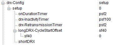
In reality, Network informs UE of this timing using RRC ConnectionReconfiguration or RRC Connection Setup as follows (Following is the example configuration from RRC ConnectionReconfiguration, but you can do the samething in RRC Connection Setup as well).
rrcConnectionReconfiguration-r8 dedicatedInfoNASList: 1 item Item 0 DedicatedInfoNAS: 27bd5ad9de05620ec101050403696d730902000000000000... .... radioResourceConfigDedicated drb-ToAddModList: 1 item ... mac-MainConfig: explicitValue (0) explicitValue ul-SCH-Config ... drx-Config: setup (1) setup onDurationTimer: psf6 (5) drx-InactivityTimer: psf1920 (20) drx-RetransmissionTimer: psf16 (5) longDRX-CycleStartOffset: sf1280 (13) sf1280: 0 shortDRX shortDRX-Cycle: sf10 (3) drxShortCycleTimer: 10 shortDRX-Cycles timeAlignmentTimerDedicated: infinity (7) phr-Config: setup (1) setup ... mac-MainConfig-v1020 physicalConfigDedicated ....
Following table shows the meaning of each DRX parameters.
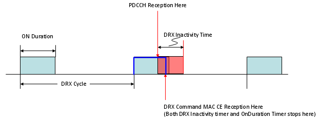
Before we go into further detail, let me give you a couple of figures that would help your understanding.
< Case 1 > : Only Long DRX Cycle is configured and No PDCCH is received during the cycle.
< Case 2 > : Only Long DRX Cycle is configured and a PDCCH is received during a cycle (You will notice the real 'ON time' May get extended depending on DRX Inactivity Timer and when the PDCCH is recieved as shown in thick Blue line).
< Case 3 > : Only Long DRX Cycle is configured and a PDCCH and DRX Command MAC CE are received during a cycle (You will notice the real 'ON time' MAY get shorter depending on exactly when DRX Command MAC CE is received as shown in thick Blue line).
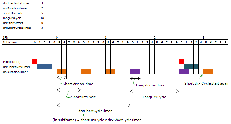
< Case 4 > : Both Long DRX Cycle and Short DRX Cycle are configured and No PDCCH is received during the cycle. This may be the most complicated case related to DRX cycle. Overall logic goes like this i) When C DRX is configured and the last DCI (PDCCH) arrived ii) drx-inactivityTimer starts and 'Wake-up status' continues until the drx-inactivityTimer expires. iii) After drx-inactivityTimer expired and the shortDrxCycle condition meet, the shortDrxCycle starts and drxShortCycleTimer starts. iv) If there is no DCI(no PDCCH) until drxShortCycleTimer expires, Long Drx Cycle starts. v) If any DCI (PDCCH) arrives during the wake-up period of any DRX cycle, go to step ii).
Following is one example showing this overall logic. This is just one example.. there can be almost infinite number of different combination is possible.
Let me give you a couple of question ? i) What would be the best period for sleeping and wake-up period ? ii) What kind of problem would happen if sleeping time is too short whereas wake-up time is very long ? iii) What kind of problem would happen if sleeping time is too long whereas wake-up time is very short ?
There would be no best answer for the question i). The answer will be different depending on situation. The answer to question ii) would be that you would not save much energy on UE side since UE is awake most of the time. The answer to question iii) would be that you would save much energy on UE side but there may be longer delay for data reception when network wants to send some data.
Now let's get into further details on exactly what happens on UE side when this DRX is working. This is very complicated process especially if both long DRX cycle and short DRX cycle are configured. Don't try to understand all the details at once. Just try to go through this process as often as possible. Try to understand only one if() statement at once.
if(drx-Config == setup) { if((Short DRX Cycle is configured/activated) && ( [(SFN * 10) + subframe number] mod (shortDRX_Cycle) == (drxStartOffset) mod (shortDRX_Cycle)) { start onDurationTimer; }
if((Long DRX Cycle is configured/activated) && ( [(SFN * 10) + subframe number] mod (longDRX_Cycle) == (drxStartOffset) ) { start onDurationTimer; }
if( (a HARQ RTT Timer expires in this subframe) && (the data in the soft buffer of the corresponding HARQ process was not successfully decoded) { start the drx-RetransmissionTimer for the corresponding HARQ process; }
if( DRX Command MAC control element is received ) { stop onDurationTimer; stop drx-InactivityTimer; }
if( (drx-InactivityTimer expires) || (DRX Command MAC control element is received in this subframe) { if (the Short DRX cycle is configured ) { start or restart drxShortCycleTimer; use the Short DRX Cycle; } else { use the Long DRX cycle; } }
if( drxShortCycleTimer expires in this subframe ) { use the Long DRX cycle; }
if( during the Active Time, for a PDCCH-subframe, if the subframe is not required for uplink transmission for halfduplex FDD UE operation and if the subframe is not part of a configured measurement gap) { monitor the PDCCH; if (PDCCH indicates a DL transmission || DL assignment has been configured for this subframe ) { start the HARQ RTT Timer for the corresponding HARQ process; stop the drx-RetransmissionTimer for the corresponding HARQ process; }
if (the PDCCH indicates a new transmission (DL or UL) ) { start or restart drx-InactivityTimer; } }
if( not in the Active Time) { CQI/PMI/RI on PUCCH and SRS shall not be reported; } }
The DRX parameters that I used are as follows. As you see, only Long DRX is configured in this example and I didn't enable the short DRX for simplicity.
Click here to download the analysis file.
Overall procedure that I applied is as follows. i) < Persistant Scheduling for both DL/UL > ii) RRC Connection Reconfiguration (Notifies the DRX configuration to UE) iii) Configure DRX parameters on Network simulator side iv) Receive RRC Connection Reconfiguration Complete v) Stop transmit PDCCH (DCI 0/DCI 1) from here to all the way to the end.
You may see from the spreadsheet that was linked above that the DRX ON does not start right away after step ii). It is because we still need to send PDCCH for step iv).
Just open up the spreadsheet linked above and follow through each row and at every row ask your self "Why this should DRX ON ?" or "Why this should be DRX OFF". This is the only way you can understand the DRX mechanism in full detail. This example is the simplest case. so you have to make it sure to understand at least this example. I will keep adding examples with various complexity.
UE Capability Information for DRX Supportability
Even though CDRX is a very important feature in terms of energy saving on UE side and a lot of live network enables this feature, it is not the mandatory requirement on UE. Therefore, even though most of UE would support this feature, there would be some UE (especially UE released at very early stage of LTE) that may not support this feature. So UE needs to inform the network about CDRX supportability and Network can optionally enable or disable based on UE capability and Network operator's requirement. CDRX supportability is informed to network via UE Capability Information message as shown below.
ueCapabilityInformation-r8 ue-CapabilityRAT-ContainerList: 1 item Item 0 UE-CapabilityRAT-Container rat-Type: eutra (0) ueCapabilityRAT-Container: c9980050c08616082058b58fff15b1ffe2fe3ffc53c7ff8b... UE-EUTRA-Capability accessStratumRelease: rel10 (2) ue-Category: 4 pdcp-Parameters .. phyLayerParameters .... rf-Parameters .... measParameters .... featureGroupIndicators: 7fcffeb2 0... .... = Indicator 1: ... .1.. .... = Indicator 2: ... ..1. .... = Indicator 3: ... ...1 .... = Indicator 4: Short DRX cycle - Supported .... 1... = Indicator 5: Long DRX cycle; DRX command MAC control element - Supported .... .1.. = Indicator 6: ....
I often see some of the misconception about CDRX and followings are some of the examples
Configuring DRX in RRC Connection Reconfiguration would be relatively simple, but verifying on whether the DRX is properly working is not that simple. Since this happens at the subframe timing, it is not possible to test the operation with eye balling. There are several steps you have to check.
Following illustration shows overall pattern of current consumption during the typical operation of mobile phone. In this page, just pay attention to the section labeled as C-DRX.
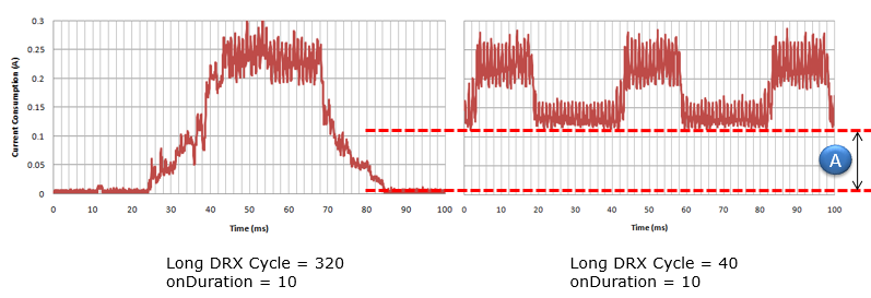
Following is an example of real current consumption measurement during the DRX cycle (if you use the high sampling power analyzer) you can measure exact timing of wake-up /sleeping time. You would notice that depending on DRX configuration the baseline current consumption would be different and the decreasing the baseline would be one of the important optimization parameters in terms of energy consumption.
|
|||||||||||||||


