|
Engineering Math - Matrix |
||
|
Stiffness Matrix
In this page, I will describe how to represent various spring systems using stiffness matrix. However, I will not explain much of underlying physics to derive the stiffness matrix. I would describe more about how to construct the matrix from simple building block matrix. You can derive the same matrix based on physics as described in FEM(Finite Element Method) - Simple Spring Model and FEM(Finite Element Method) - More Complicated Spring Model. I would recommend you to go through these page and have some understandings on physics background first if you don't extremly hate physics :). However, if the system gets more complicated (i.e, more springs gets connected) it would be difficult to derive the matrix purely based on physics. You will notice how convinient it is to construct the matrix in the page described here.
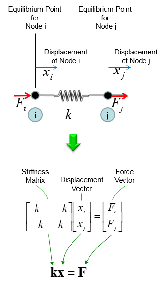
Most of the stiffness matrix starts with the following building block. This is for a system made up of the single spring and both ends of the spring can move freely in horizontal direction. The stiffness matrix and the equation for hook's law is as follows. The stiffness matrix for any spring system, however complex it is, can be construced by combining these building blocks.
Another important building block is shown below. It is also a single spring system but in this case one end of the spring is fixed. Basically the stiffness matrix for this system can be derived from the case of free ends (shown in previous section). Fixed end means that the displacement of that end is always zero. The derivation of stiffness matrix for this case is based on this fact (i.e, displacement = 0 at the fixed end).
Overall procedure to derive the stiffness matrix is shown below. At Step (A) : Illustrate the system At Step (B) : Construct stiffness matrix and Hook's formula as if there is no fixed end (i.e, assume all ends are free). At Step (C) : You can take two different procedure at this point. Case (1) Remove the columns and rows that is associated with fixed node (fixed end). In this case, node (i) is fixed. So column (i) and row (i) is removed and we will get the resulting equation as (1). In this case, the size (dimension) of the matrix decreases. This is the most typical way that are described in most of the text book. Case (2) Replace the columns and rows that is associated with fixed node (fixed end) with zero. Then you will get the equation as in (2). In this case, the size of the matrix does not change as in free end case. This is not usually introduced in any textbook, but I am introducing this case since it would be easier to contruct the matrix if you implement the system with software program.
Now let's see a little bit more complicated system and see how the building blocks shown above are used to represent more complicated system. In this system, you have two springs connected together as shown below.
Now you can divide this system into two building block as shown below. However complex system it is, you can always breakdown the system into multiple building blocks.
Now from this building block, you can construct the stiffness matrix and Hook's equation as follows. Step (A) : Breakdown the system into building blocks Step (B) : Construct the stiffness matrix and Hook's equation for each building block. And label each column and raw with the number of each node. Dimension of each matrix will be always 2 x 2. If you get familiar with this process, you may skip this step and go directly to Step (C). Step (C) : Create a big stiffness matrix and Hooks equation that can accommodate the whol system. The size of the matrix became N by N, where N indicates the total number of nodes in the system. Since the number of the nodes in this example is 3, the size (dimension) of the matrix become 3 x 3. Then, plug the matrix of the building blocks into the large matrix according to the index number. Step (D) : Superimpose all the matrix equation from Step (C) into single system matrix. In this process, just do matrix sum of stiffness matrix. Do vector sum of displacement vector. But you should be careful with combining Force vector. As you see in the result, the force vector F is a little bit different from vector sum of each building block. If you do vector sum of F vector, it would become [F1, 2 F2, F3]. However, you have to divide (2 F2) by 2, because the node (node 2 in this case) is used twice.
Now let's look at a variation of two spring system. As you see in the following illustration, it is almost same as previous example. The only difference is that node 1 is fixed in this example. So the overal procedure for matrix construction is very similar to previous example. Step (A) : Illustrate the system Step (B) : Construct the stiffness matrix and Hook's equation for the case where there is no fixed node. Step (C) : You can take two different procedure at this point. Case (1) Remove the columns and rows that is associated with fixed node (fixed end). In this case, node (i) is fixed. So column (i) and row (i) is removed and we will get the resulting equation as (1). In this case, the size (dimension) of the matrix decreases. This is the most typical way that are described in most of the text book. Case (2) Replace the columns and rows that is associated with fixed node (fixed end) with zero. Then you will get the equation as in (2). In this case, the size of the matrix does not change as in free end case. This is not usually introduced in any textbook, but I am introducing this case since it would be easier to contruct the matrix if you implement the system with software program.
Now I will show you another example which is much more complicated shown above. I have shown you the exact same case in FEM(Finite Element Method) - More Complicated Spring Model. But the way to construct the stiffness matrix will be a little bit different here. Personally I prefer the procedure that I will show you in this page. It will take a little bit more steps but you will be able to create the stiffness matrix without much thinking or confusion if you use the method being used in this page.
As a first step, I changed the system a little as shown below. This is to convert the fixed node to free node. and I will derive the stiffness matrix and Hook's equation for this all free-end system first. And I assigned the number Zero to the freed node. The reason why I put the number 0 is to keep the same number for all the other nodes as in the original.
First, you need to figure out the size of the stiffness matrix for the whole system. Do you know what it is ? It is 4x4 because you have four nodes (0,1,2,3) in this example. With this in mind, let's go through matrix construction.
First, constuct fill in the matrix with stiffness values for the spring k1 which is connecting the node 0 and node 1. It become as follows.
Next, constuct fill in the matrix with stiffness values for the spring k2 which is connecting the node 1 and node 2. It become as follows.
Next, constuct fill in the matrix with stiffness values for the spring k3 which is also connecting the node 1 and node 2. It become as follows.
Next, constuct fill in the matrix with stiffness values for the spring k4 which is also connecting the node 1 and node 3. It become as follows.
Last, constuct fill in the matrix with stiffness values for the spring k5 which is also connecting the node 2 and node 3. It become as follows.
Now combining (superimposing) all of the matrix, you will get a matrix equation as follows.
The above matrix is for the system without any fixed node. But the original problem is to construct matrix for the node 0 fixed. So we need to convert this all free-ends system matrix into the one with node 0 fixed. As you learned from the examples above, it is very simple as shown below. Case (1) Remove the columns and rows that is associated with fixed node (fixed end). In this case, node (i) is fixed. So column (i) and row (i) is removed and we will get the resulting equation as (1). In this case, the size (dimension) of the matrix decreases. This is the most typical way that are described in most of the text book. Case (2) Replace the columns and rows that is associated with fixed node (fixed end) with zero. Then you will get the equation as in (2). In this case, the size of the matrix does not change as in free end case. This is not usually introduced in any textbook, but I am introducing this case since it would be easier to contruct the matrix if you implement the system with software program.
|
||


