Communication Technology is a special technique to send data from one place to another. A typical concept can be illustrated as follows. As you see, there are at least three major components getting involved in any kind of communication process, a sender (transmitter) and reciever and the channel. You would intuitively know what is transmitter and reciever.

Figure 1. The whole subject in one picture, and the middle element is the one that makes it a subject at all. A transmitter and a receiver are things an engineer builds. The channel is a thing an engineer is given.
The cloud is drawn as a cloud on purpose : it is labelled Channel (Media) and nothing inside it is specified. What is inside depends entirely on the link.The arrow runs one way : the drawing covers a single direction. The return path and everything it needs is left out.Both ends are drawn as dish antennas : the picture is a wireless one. The paragraph above names a serial cable and a LAN cable as channels too.
Since this is an introductary pages for communication system, I will touch with some some high level topics about communication system in this page. Followings are the list of topics that will be dealt with in this page.
- What is 'channel' ?
- Overall Architecture of Communication System
- Challenges in Communication / Critical Factors in Communication System Design
- What to study ?
- Refernece
What is 'channel' ?
Channel is a physical media through which the transmitted signal follow. For example, in a very simple communication system like RS232. What you call RS232 cable (made up of copper) is the channel. Let's think about ethernet communication (wired LAN). In this case, what you call LAN cable is the channel (one PC can be an transmitter and another PC can be a reciever.). How about mobile communication like a mobile phone ? My mobile phone and a basestation can be a transmitter and reciever and the air space and all other obstacles(e.g, mountain, building etc) in between a mobile phone and a base station can be a channel.
In short, a signal (data) from a transmitter always go through a specific channel to reach the reciever. Studying the communication system means understanding the characteristics of those three major components, Transmitter, Channel, Reciever.
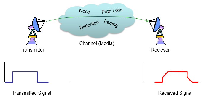
Figure 2. The same picture with the cloud opened and the consequence drawn underneath. Four things are named inside the channel. The pulse at the bottom right is what they did to the pulse at the bottom left.
Four effects are named, not one : Path Loss, Distortion and Fading, plus a fourth the picture spells Nose and means Noise.The transmitted pulse has square edges and the received one does not : the rise and the fall have both been sloped. The flat top is no longer flat.The received pulse is also lower : amplitude has been lost as well as shape. That is the path loss in the cloud showing up in the waveform.The word Reciever is spelled that way in the picture : the prose on this page uses the same spelling, so the two agree.
Now let's loot at the illustration shown above and assume that a transmitter sent a signal as shown in the left bottom (in blue) the signal detected by the reciever is shown in the right side (in red).
What is the first thing you noticed in the illustration ? It would be that the transmitted signal and the received signal is not exactly same.
What is the difference ? Let's look at following illustration. The difference in this specific example is as follows.
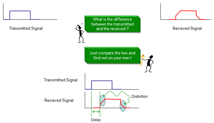
Figure 3. The two signals on one time axis, so that the differences can be named rather than sensed. The lower half answers the question the upper half asks.
The figure names exactly two differences : a Delay between the two starting edges, and a Distortion marked by two grey ellipses on the sloped edges.The delay is measured between the green lines : one at the start of the transmitted pulse and one at the start of the received pulse. A delay cannot be seen any other way.The two ellipses sit on the edges, not on the flat part : distortion shows first where the signal changes fastest. A flat stretch hides it.The stick figures carry the instruction : the second box asks for the two signals to be compared. The lower half of the picture then does it.
The sentence above the figure promises a list. The list arrives only in the picture. Written out, this example shows three differences. Nothing arrives at all for a while. The rise and the fall are no longer vertical, and the peak is lower.
The first of the three differs in kind from the other two. Delay is not damage and cannot be designed away. It is the time the signal spends travelling. A metre of that journey costs 3.34 nanoseconds and a kilometre costs 3.34 microseconds. One trip up to a geostationary satellite costs 119 milliseconds.
Whether that matters depends entirely on the rate. One microsecond is under one per cent of a bit at 9600 baud. At the WCDMA chip rate of 3.84 Mcps it is nearly four whole chips. The same delay is negligible in one system and disastrous in another.
Delay is arithmetic, distortion is a problem : the first follows from distance and the speed of light. Only the second can be reduced by design.A cable is slower than free space : at a velocity factor of 0.66 a kilometre of copper costs 5.05 microseconds rather than 3.34.The edges carry the damage : a square pulse asks for infinite bandwidth and the channel supplies a finite amount. The corners go first.
Now you would ask why we have this kind of differences ? Intuitively you may think of several possible reasons as follows.
i) Transmitter didn't send clear signal. (It was supposed to send the exactly same shaped as shown in the illustration, but it failed to send such a clean signal).
ii) Reciever didn't detect the signal very well.
iii) The signal was changed (distorted) while it follow through the channel.
Any of these problem can happen. Actually in most cases, all of these problem happens simulteneously. The purpose of studying communication technology is to find techniques to reduce these problems as much as possible and find out proper answers to following questions.
i) How can I design a transmitter that can transmitter a signal exactly as I intended ?
ii) How can I reduce the influence of the distortion (and noise) created by the channel ?
iii) How can I design a reciever that can accurately detect the signal as I intended ?
You may just recall all those mathematical equations and techniques like transfer functions, convolution, deconvolution, impulse response, filter, fading etc from text books and have no idea on why we need those things and how those things gives you the answers to the fundamental questions listed above ?
What would be the most difficult question among them ? I think it is question ii) and very large portions of theories and techniques that we learn from the text book is mainly to find the answers to the question ii). In other words, if we can find and use as we like a medium(channel) which does not distort the signal going through it, most of communication text book can be written in much simpler way.
Overall Architecture of Communication System
Following is an example of a typical communication system. More specifically, it is a typical structure of wireless communication. Usually, the parts illustrated in green can be seen both in wireless and wired communication, but the parts illustrated in violet would be seen in wireless communication. What you usually see in digital communication text book or signal processing books are related to the parts in green. What you see in RF text book are related to the parts in violet. I would not exaplain each of these components in detail here. The purpose of putting this illustration in this page is just to give you a big picture of a whole communication system.
For the details of the parts illustrated in green, refer to 'Communication Technology' and Signal Processing and Communication page in Matlab/Octave pages. For the parts in violet, I would try posting other separate pages in the future. For now, just try to follow through each components and make a story on your own based on your common sense.
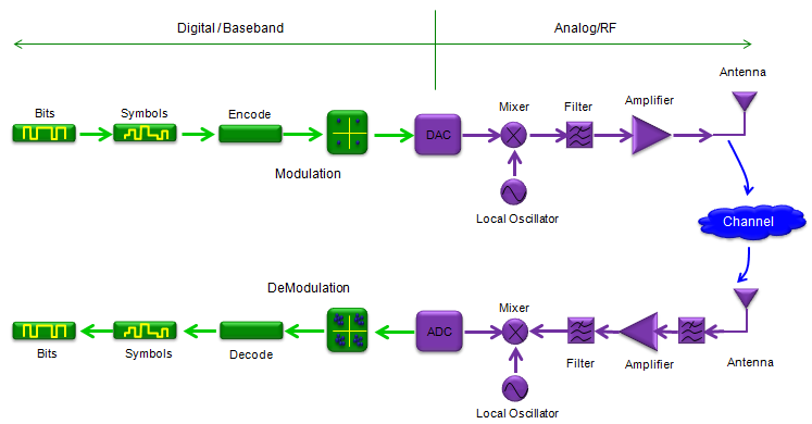
Figure 4. One direction across the top, the channel down the right, and the same chain in reverse along the bottom. Every block going out has a partner coming back.
The green vertical line is the real division : it separates Digital / Baseband on the left from Analog/RF on the right. The DAC and the ADC sit on that boundary.The colours repeat that split : green blocks are the baseband side and violet blocks the radio side. That is the colour code the paragraph above uses.The chain is a mirror, block for block : Encode meets Decode, Modulation meets DeModulation, DAC meets ADC. Each receive block undoes one transmit block.The mixers are the only blocks fed from the side : a Local Oscillator reaches each one. Moving a signal to and from the carrier needs a reference that neither the data nor the antenna supplies.The channel appears as one cloud with no blocks in it : the same choice as Figure 1, and the reason the channel section exists.
Actually the system structure of a communication system show above is only for one portion (physical layer) of the system. Only very simple communication system can be built from this structure only. In most of the communication system you are using in daily life has much more complicated structure. In most communication system, a lot of other complicated layers are sitting on top of the physical layer as illustrated below. Each of the blocks in this illustration requires a huge number of engineers for research, development and testing and this full structure forms a huge industry.
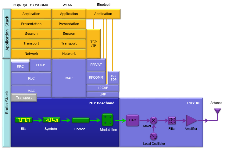
Figure 5. The same chain again, now drawn as the floor that three different protocol stacks stand on. The bottom two bands are the transmit half of Figure 4, redrawn underneath everything else.
The bottom two bands hold the transmit chain : PHY Baseband holds Bits, Symbols, Encode, Modulation and the DAC. PHY RF holds the Mixer, Filter, Amplifier and Antenna.The left edge names the two halves : Application Stack above and Radio Stack below. The rest of the figure is arranged around that division.Three columns share one floor : 5G(NR)/LTE / WCDMA, WLAN and Bluetooth have completely different radio stacks. The kind of physical layer underneath is the same.The radio stacks are the part that differs most : the cellular side has RRC, PDCP, RLC and MAC. WLAN has a single MAC block, and Bluetooth has PPP/AT, RFCOMM, L2CAP and LMP.The application stack converges again at the top : the cellular and WLAN columns both run the familiar layer names. Bluetooth reaches TCP/IP by its own path.
Putting the two figures side by side answers a question that neither asks on its own. Figure 4 looks like the whole system when it is read alone. Figure 5 shows it occupying the bottom two bands of something much larger. The physical layer is the part this site spends most of its pages on. It is one floor of the building.
The relationship runs the other way too. Everything in the upper bands of Figure 5 exists because the channel of Figure 2 is imperfect. Retransmission, segmentation, acknowledgement and scheduling are all answers to a physical layer that sometimes fails. A perfect channel would leave most of those blocks with nothing to do.
Challenges in Communication / Critical Factors in Communication System Design
In most of the communications, you would face several major challenges you (or the industry) need to handle as listed below. As you study communication technologies, you would notice that there are a lot more things to study than you might have imagined at the beginning. Huge portions of those details are required to handle these challenges.
- Fast and Reliable (Wide Bandwidth and Powerful Error Handling)
- Sharing (Sharing a common media with many other devices)
- Scalable
When you study the topics in communication technology, just asking yourself a question as follows and finding the rough answer can be an excellent starter for you.
The question is 'Is this topic (techniqu) for increasing speed or increasing reliability or media sharing or Scalability related ?;
That question names four things and the bullet list above it names three. The first bullet carries speed and reliability together and the question separates them. The split is the more useful one. They are bought with different currencies and they pull against each other.
Speed is bought with bandwidth or with power. The exchange rate between the two is not favourable. A 20 MHz channel at 20 dB of signal to noise carries about 133 Mbit/s at best. Doubling that to 266 Mbit/s takes either a second 20 MHz of spectrum or another 20 dB of signal. The second route is a hundredfold increase in power for the same result.
Reliability is bought with rate. Every specification names the price. A rate 1/3 code transmits three bits for every bit of payload. Two thirds of the channel is spent on making the remaining third survive. Choosing a weaker code returns that capacity and surrenders some of the protection with it.
Sharing is bought out of each device's own share. Eight users splitting one 133 Mbit/s channel equally have 16.6 Mbit/s each. Sixty four of them have 2.1 Mbit/s. Every technique for separating users exists to make that division cheaper. Time, frequency, code and space are the four dimensions used for it.
Scalability is the one the page leaves without a parenthesis, and it is not like the other three. The other three are quantities to be traded. This one is a requirement that the same design keep working far outside the case it was tuned for. A cell serving one device and the same cell serving a thousand need the same procedures. Overhead that is negligible at a thousand is most of the traffic at one.
Challenge |
What it buys |
What it is paid for with |
more bits in the same second |
bandwidth, or power. Doubling the rate needs twice the spectrum or 20 dB more signal. |
|
fewer bits wrong at the far end |
rate. A rate 1/3 code sends three bits for every one of payload. |
|
many devices on one medium |
each device's share. Eight equal users on one 133 Mbit/s channel get 16.6 Mbit/s each. |
|
the same design working at one device and at a thousand |
efficiency at both ends of the range, because signalling sized for a thousand is waste for one. |
Table 1. The four axes the section names, and the price of moving along each one. No row is free, which is why a design has to choose.
Speed and reliability are separate axes : the closing question is right to split them. Coding trades one directly for the other.Power is a poor substitute for bandwidth : 20 dB of extra signal buys what a second copy of the spectrum buys. That is why spectrum is the scarce resource.Sharing is division until a dimension is found : time, frequency, code and space are the four dimensions available.Scalability is a constraint rather than a quantity : it does not trade against the other three. It limits which trades are allowed.The suggested question works because nothing is free : a technique that improved one axis at no cost would already be in every standard.
What to study ?
To study in almost any engineering field, the biggest question would be 'do I need to learn theory first ?' or 'do I need to jump into an applications and have some hands-on experience first ?'.
As you may guess, there wouldn't be any firm and clear answer for this. In whichever way you go first(theory first or hands-on first), you would feel something missing because of the way you haven't gone through.
If you go with theory first (like starting the area in University), you would think 'why do I need to learn all these strange things ?', 'what does this mean in practical sense ?'. 'Would this really help anything in daily engineering job ?'. Without any clear answer to these questions, it would be very challenging to keep you motivated (or even being awake) to stick to those theories (textbooks). Without practical experience, it would be difficult for you to find answers to these questions.
If you go with hands-on (experience) first (like staring the carrier path that is different from your university background), you may come across many situations where 'I know this is working, but why this is working ? how this work as I see now ?'. Why they (the industry) came out with such a strange looking algorithms and equations in the technical specification ?'. To find the answer to these questions, you would need some study on theoretical background of the area in which you are working.
Studying (or working ) in the field of communication, what kind of theory you need to study ? Following illustration shows some theories you wound need in this area. This list is from Ref [2] and after spending over 10 years in wireless communication technology and as a person who has been working in a completely different area from University background, I agree with this suggested list. If you are working in electronic/electrical engineering based communication technology (usually physical layer or lower layer), you might already have some familiarity on Modulation / Fourier Theory. If you are working in computer engineering based communication, you might be more familiar with Detection Theory. But whatever you started first, I think you need to be familiar with all of these theories eventually. Personally I am still struggling a lot with Probability Theory/Random Process and have difficulties in associating these theory with the area I am working.
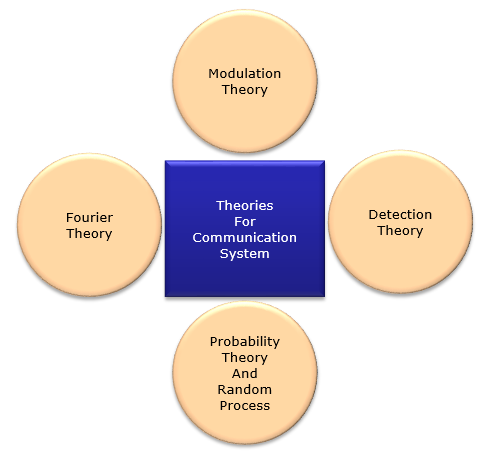
Figure 6. Four subjects and no ordering between them. They are arranged around the centre rather than in a sequence, because none is a prerequisite for the others.
Two of the four are about signals and two about uncertainty : Fourier and Modulation describe what a waveform is. Detection and Probability describe what to believe about it.Probability gets the longest label : Probability Theory And Random Process is one circle rather than two. A random process is what probability becomes once time is involved.Nothing in the figure is specific to any technology : the same four cover a serial cable and a 5G carrier.
The figure lists four theories and the channel section lists three questions. The page never joins them. Doing that turns a reading list into a plan.
Fourier Theory answers what a signal is made of. That is what decides how much of it survives a channel of limited bandwidth. Modulation Theory answers how to put data onto something the channel will carry, which is question one. Detection Theory answers how to decide what was sent from what arrived. That is question three.
Probability Theory and Random Process sits underneath question two. The page itself calls that one the hardest. Noise and fading cannot be written as formulas of time, only as distributions. The theory that fits them is therefore the theory of what is not known exactly.
Modulation answers the transmitter question : how to turn bits into a waveform that the channel accepts.Detection answers the receiver question : how to choose the most likely transmitted symbol from a distorted and noisy one.Probability answers the channel question : the channel is described by statistics rather than by an equation. That is why it is the hard one.Fourier runs underneath all three : bandwidth, filtering and distortion are all statements about frequency. Every other theory here borrows its language.
Refernece
[1] MIT OPENCOURSEWARE : Introduction to EECS II: Digital Communication Systems
[2] Introduction to Analog & Digital Communications by SIMON HAYKIN, MICHAEL MOHER