|
Embedded System - Arduino |
||
|
Arduino Uno - R3
I will describe some details (or quick tips) for the board that I first used. If you haven't purchased any board yet or you just bought it but no previous experience with Arduino, this page would help you get familiarized with the board and software environement.
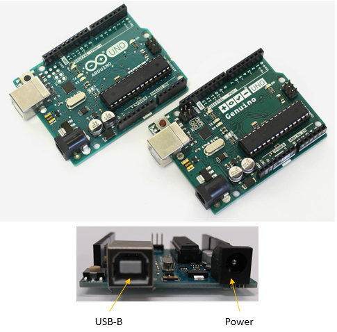
Following shows how the board (Arduino Uno) looks like. Depending on where you bought it you may see different labels on the board. If it is US/Canada, you would see 'Arduino' and if you are in other country, you would see the label 'Genuino'. If you buy (or order) Arduino board only, it would come with the board only without any USB or power adaptor or anything else. So you are ready to invest a little more in order to operate this board. As I mentioned in Before You Buy page, the type of USB is USB-A. So you need to have USB-A to USB-B convert cable. Do I need any power adator as well ? If you are using Arduino connected to PC all the time (as in most training or study), you don't need any additional power adaptor. But if you load a developed program onto the board and just keep running it without PC, you need power adaptor.
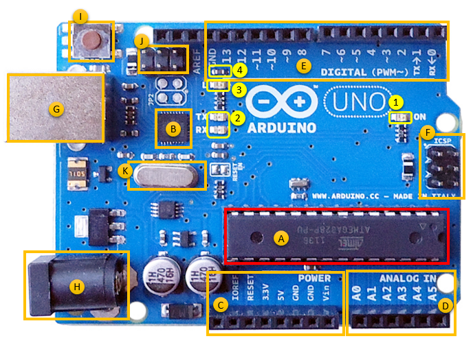
If you want to know some more details of the board and major chips and I/O (Input/Output) pins on the board, following magnified picture would help you. My sight is already getting weaker due to aging -:), so often I take the picture of the board with my smartphone and look into the details on the board like this.
If you go to Arduino Uno home page, you would get all the detailed information and related documents about the board. First thing you may refer to would be the schemeatics of the board . It would look a little bit too complicated and confusing if you don't have much experience of electrical engineering, but it would start making sense as you keep checking the schematics whenever you are trying something with the board. Try to mark the path on the schematic along which the electric signal flows whenever you makes an application. This would be a good practice to understand the schematics. On the schematics, you would see two important IC (Processor). One is ATMEGA16U2 (labeled as (B))and the other one is ATMEGA328P (Labeled as (A)). You may easily get the datasheet of ATMEGA16U2, ATmega168 and ATMEGA328 on the internet (from ATMEL home page).
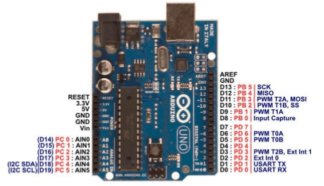
In user's perspective, the most important thing to know would be the function of each I/O pints on the board and those pins are as follows. The Red label is the label for the pin on Arduino Processor (Atmega 168) and the black label is the pin on Arduino board. The I/O Pin number used in Arduini IDE programming is based on the black label.
( Source : http://www.slideshare.net/twunishen/hackathon-taiwan-5th-arduino )
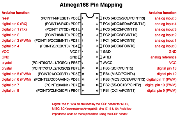
Following mapping (from Arduino homepage) shows more clearer understanding on the mapping between Atmega 168 chipset and Arduino I/O ports.
( Source : https://www.arduino.cc/en/Hacking/PinMapping168 )
Download and Install Arduino IDE (Integrated Development Environment)
You can download the Arduino Software (Arduino IDE) from the download menu in Arduino home page. It is recommended to download the latest version, but I am not sure if all of the Arduino clone board are compatible with the latest IDE (My guess is that if you can get the proper hardware driver for the clone board, it would be OK with IDE. But I am not sure). If you just buy Arduino original, there wouldn't be any issue as far as I've tried.
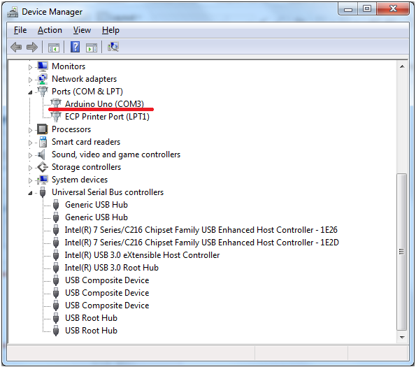
When you install Arduino IDE, it will install the device driver for all the Arduino Board (I mean Arduino Original board). If these driver is properly installed, you should see following item under 'Ports' item in Device Manager when you plug in Arduino board to your PC USB port. (If you don't see this port, you would not run any program in Arduino IDE. You can still launch Arduino IDE and create/edit the code, but you cannot run the program)
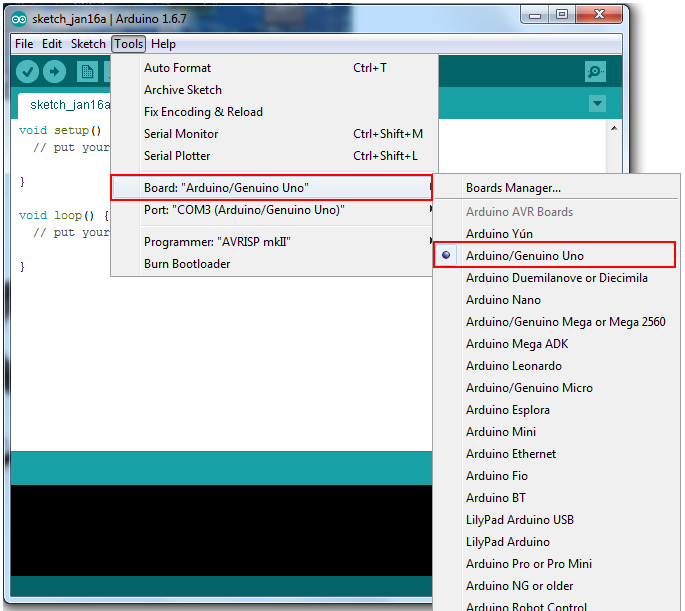
If the driver installation is properly done and the hardware is recognized properly as shown above, launch Arduino IDE. Then, specify the Arduino Board that is connected to your PC by the menu as shown below.
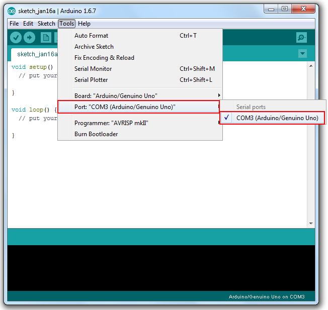
Then specify the communication port that is mapped to Arduino board by the menu as shown below.
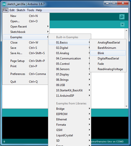
Once everything is done properly, you can try a real program that does something to the Arduino board. Do I have to make any specific test circuit and connected to Arduino board ? No. Just for basic operation test, you don't have to make any addional board and you don't need to write any Arduino program either. Just try as follows.
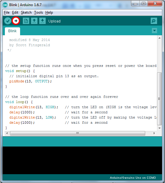
Open the example program titled as 'Blink' as shown below.
You will see a small program as shown below. You don't need to understand the meaning of each lines in the code. For now, just press [Run] button (Marked in Red Circle).
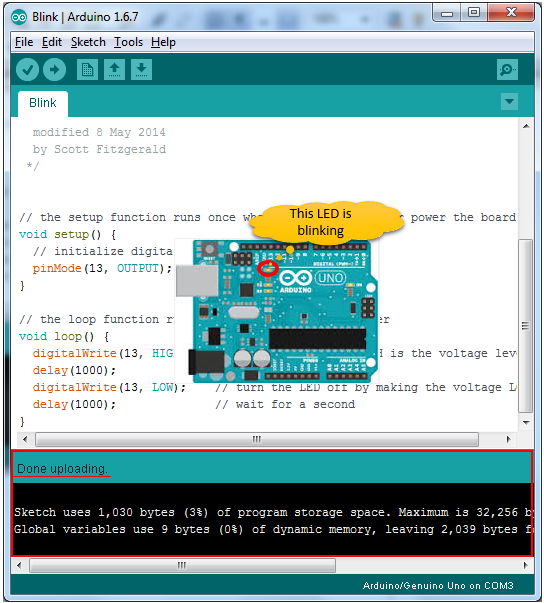
If the program compile and uploading to the board, you will see the message at the bottom of IDE and see the LED marked in Red on the board will flash.
|
||