|
Embedded System - Arduino |
||
|
Motor Basics
By the time you get familiar with basic operation and spend some time with flashing LEDs, you would want to try something moving. And in most case the first moving things poping up in your mind would be a motor.
As a complete beginner in electronics, I always tend to seek the easiest way to do this and I was thinking if can can connect the motor directly to the Arduino pin (or with an addition of a small resistor) as I did with LEDs. But life is not that easy... Connecting a motor directly to the Arduino pins would not work and to make it things worse it may break Arduino board. So read through following section before you try anything with a motor. It can be a good study as well.
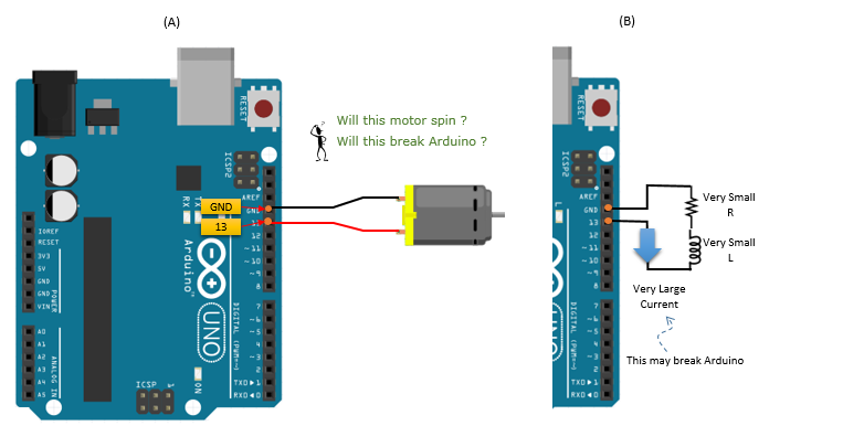
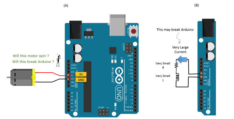
Look at the connection shown in (A) of [Figure 1] and think of whether the motor would spin ? or would Arduino board be OK ? The answer is "Motor would not spin because it may break Arduino first". The circuit shown is an example of short circuiting (theoretically this is not a short circuit, but practically it is almost like a short circuit), where infinite amount of current is able to flow through the series. In this case, the motor will not spin because very large current flow will burn the board as soon as the battery is connected. As most people would think, the board does not have built-in protective features that can limit current flow. Just like every other circuit elements(such as capacitor, transistor, LED light, etc) motor and Arduino board have negligible resistance within themselves. If you represent the connection (A) into a electrical circuit symbols, it would be as in (B). It would be easiear to understand to understand how current is affected by battery source and internal resistance of circuit elements, recall i=V/R. In this case, no matter how low the voltage(V) of the battery source is, i will be infinitely large because the total resistance of the circuit is nearly zero. To limit the amount of current flow, connecting a resistor to the circuit is necessary. Refer to Case B for further details about this.
[Figure 1] Direct connection to Pin 13 (PWM Output)
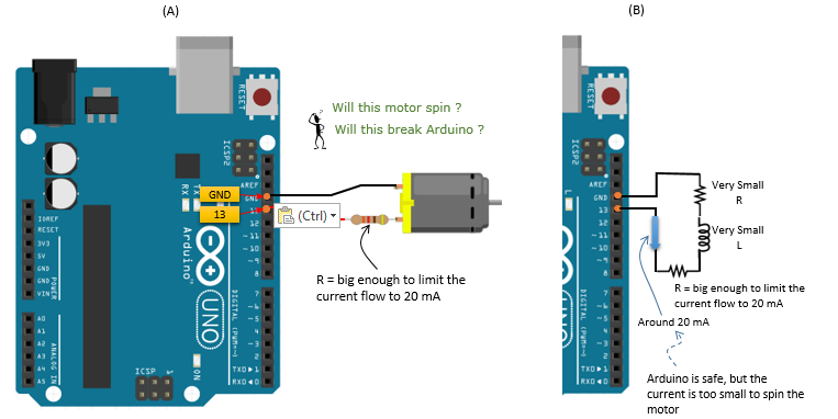
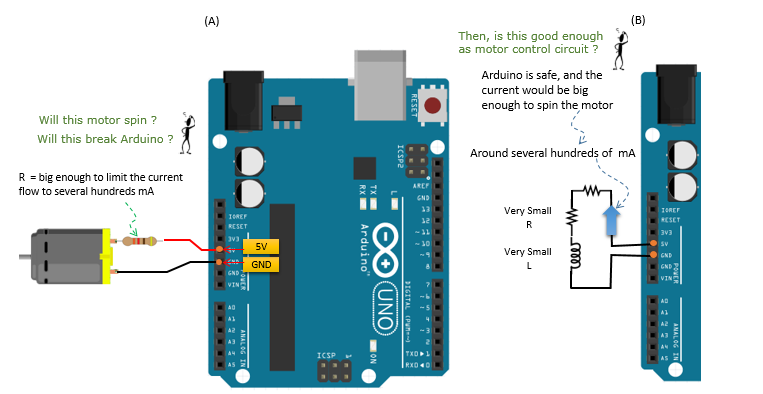
Look at the connection shown in (A) of [Figure 2] and think of whether the motor would spin ? or would Arduino board be OK ? The answer is "Arduino would be safe but the motor would not spin". To prevent the too large current flow that was mentioned in [Figure 1], we used a specific resistance to limit the current flow to 20mA, which is the maximum current flow that Arduino digital output pin is able to withstand. Unlike [Figure 1], the Arduino board will not break. However, the motor will not spin because it does not receive enough current flow to operate. Most of DC motor requires a couple of hundreds of mA to spin its axle
[Figure 2] Direct connection to Pin 13 (PWM Output) with a resistor
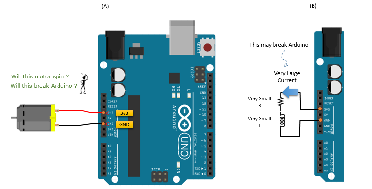
Look at the connection shown in (A) of [Figure 3] and think of whether the motor would spin ? or would Arduino board be OK ? The answer is "Motor would not spin because it may break Arduino first". Observing the circuit, this case is no different from [Figure 1] except that the pin is connected to 3.3V output in stead of digital output pin. Just because the output voltage is lowered to 3.3V, it does not make it any safer for the Arduino board. The amount of current flow is still very large because the resistance of Arduino board and the motor is negligible. Recall i = V/R. Regardless of the magnitude of V, the current will be very large but this pin can withstand only around 50mA. Again, this is known as �short circuiting�, which damages the Arduino board(i.e. burning).
[Figure 3] Direct connection to 3.3V Output
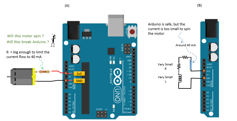
Look at the connection shown in (A) of [Figure 4] and think of whether the motor would spin ? or would Arduino board be OK ? The answer is "Arduino would be safe but the motor would not spin". Observing the circuit, this case is no different from [Figure 2]. Even though the Arduino board is safe since the current does not surpass the amount of current flow that the board is able to withstand, there is not enough current provided for the motor to spin the motor.
[Figure 4] Direct connection to 3.3V Output with a resistor
Look at the connection shown in (A) of [Figure 5] and think of whether the motor would spin ? or would Arduino board be OK ? The answer is "Motor may not spin because it may break Arduino first". The circuit reflects that the case is no different from [Figure 1] and [Figure 3]. This is simply another example of short circuiting which will flow current big enough to break Arduino board. As discussed before, resistance in Arduino board, wires, and motor is nearly zero, therefore this connection would produces almost infinite current flow according i = V/R.
[Figure 5] Direct connection to 5V Output
Look at the connection shown in (A) of [Figure 6]and think of whether the motor would spin ? or would Arduino board be OK ? This connection would spin the motor without breaking Arduino board, because this pin can withstand several hundreds of mA which is big enough to spint the motor, but would not flow too much current because of the resistor. However, I don't personally recommend to use this connection either. Even though the current when the motor is spinning can be within the normal range of the pin operation, but when the motor stalls it may draw so much current that may damage the pin.
[Figure 6] Direct connection to 5V Output with a resistor
Then, What am I supposed to do ?
In previous section, you see a lot of 'Don't do this' case. If you are really at the beginner's level, you might have thought of (or even tried some of the cases and might have burned down the board). Personally, I really thought of each of the 'don't do' case even though I haven't really tried.
Then you may say.. 'What am I supposed to do ?'.. What should I do to spin the motor without burning the arduino board.
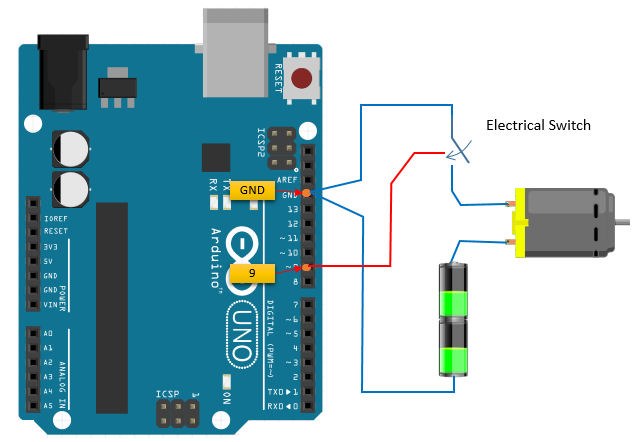
The answer is 'to build a power supply circuit to motor sitting out side of Arduino board and let Arduino just to turn on/off the switch of the power supply circuit. The basic structure of the power supply circuit and connection to Arduino board an be illustrated as follows.
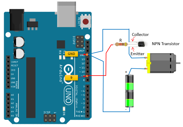
Figure 1, 2, and 3 all represent the same circuit in different variations, which makes it easier to understand how transistor works in an Arduino circuit designed to operate and control the speed of DC motor.
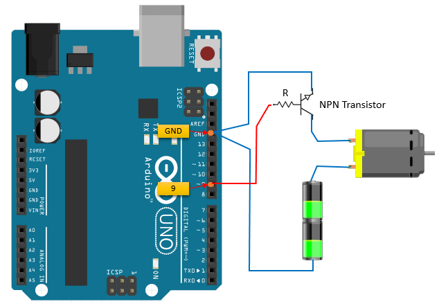
As you can observe, NPN transistor is a switch of the motor that is connected in series to DC motor, battery, resistor and output pin of Arduino board as a circuit.
Figure 1 is the best diagram to refer to when you are first trying to understand how the transistor works. Before learning about how it works, consider referring to Figure 2 and Figure 3 because it shows how all the elements are connected together to operate the DC motor, in circuit notation and the actual circuit diagram, respectively. If they are not connected properly, DC motor cannot operate properly, which indicates that having thorough knowledge on the characteristics/features of each circuit element is not enough to design a circuit.
Transistor is a very simple element that is able to turn the DC motor on and off by Arduino command. As shown in the figures, the Base pin of the transistor is connected to Arduino output pin 9 (or any PWM pin), which is connected the way it is to receive its commands as well as having a resistor in the way. The resistor is connected to prevent excess current flow that can damage the transistor and to control the amount of the current supplied to the motor.
[Figure 1]
[Figure 2]
[Figure 3]
How to change the speed of spin ?
In previous section, we learned on how to switch on (spin) and switch off (stop) the motor using Arduino. You might feel excited just by the fact that you can spin and stop a motor with Arduino and very simple program. However, this excitement would not last long... soon you would start thinking "Now.. I have only two states.. spinning at full speed or stand still. Is there any way to spin the motor at various different speeds ?". Of course, it would be easy if you have output pin of which you can flow a specific amount of the current and voltage as you like. However, the output voltage of Ardiuno output pin is set to be a specific single value and the amount of the current is determined not by Arudio program but by external circuit connected to it.
How can we control of the speed of motor spin with this kind of restriction ? There is way to do it. The way to do this with only two states of output pin is called 'PWM (Pulse Width Modulation)'. However, understanding how PWM works would not be easy. Let me try to explain how PWM works.
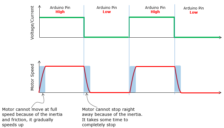
Let's think that you connect a Motor switching circuit to an Arduino output pin and set the pin state as shown on the top graph. Let's assum that you set the pin High for 1 second and then set it Low for 1 secondand repeat this procedure. The output voltage (or current) of the pin can be plotted as in plot at the top (green plot) Then, the motor would spin for 1 second and stop for 1 second and repeat this. If you plot the speed of the motor spin, it would be like as the plot at lower track (Red). One thing you would notice is that the speed of the spin does not immediately goes to max when switching on and does not stop immediately when switching off. It will take some time to reach the full speed and zero spin (stop). Using this property, we can change the overall speed of the spin just by changing the pattern of switch on/off.
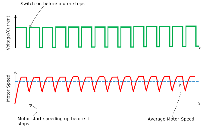
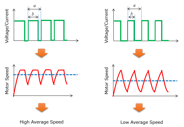
Now let's suppose we switch on/off more rapidly (actually much more rapidly) as in green plot on the top. Let's suppose you turn on the switch for 2 milli seconds and turn off for 1 milli seconds and repeat this. As explained above, the motor speed would gradual increase when you turn on the switch and the speed gradually decrease when you turn off the switch. However, this time the switch off period is very short and then you turn it on. In this case, you turn on the switch before the motor completely stops and the motor spin goes faster again.. and this procedure will repeat. If you plot the speed of the motor spin it would look like the red plot. As you see, the motor spin speed goes up and down periodically. However, this speed change goes so fast you would not notice the speed changes.. instead you would sense that the motor spins at a constant speed as indicated in blue dotted line.
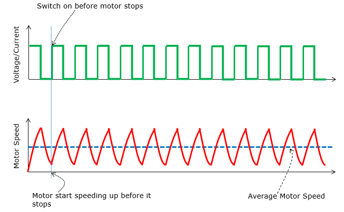
Now let's changing the switching pattern a little bit as in the following green plot. Comparing to the green plot in previous case, the switch ON time got a little bit shorter but switch OFF time got a little bit longer. Let's assume that the switch ON time is 1.5 ms and OFF time is 1.5 ms as well and the pattern of ON-OFF repeats. Now think of how the motor spin pattern would change. Since swtich ON time got shorter and switch goes OFF, the motor would have less time to catch up the speed and then would slow down when switch goes off. After the switch went OFF, it would have longer time for the motor to slow down and then start increasing the speed when the switch goes ON. This pattern can be illustrated like the Red plot. As you see, in this case the speed of the spin fluctuate even more widely than in previous case. However, since this speed change happens so fast you don't recognize the pattern just by looking at it. As a result, for the outside observers it looks as if the motor spins at the average speed as indicated by the dotted blue line.
Now you have seen two examples showing the different average speed of the motor spin. To refresh your memory (hopefully refresh your undestanding as well), let me redraw the previous two cases onto single diagram as shown below. Take a look at the bottom graph (Red graph and the dotted blue line). You would see the obvious difference between the two. Think of what made this obvious difference. It is the ratio of ON/OFF time in switching. I hope you would get some sense (feeling) of how this work.
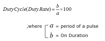
The duration of ON time in a switching cycle is called 'Pulse Width'. So you can say "We can control the motor speed by changing Pulse width" and this kind of technique is called 'PWM (Pulse Width Modulation)'. Speaking more specifically, the average motor speed is determined by the Radio of ON time within a single cycle. This ratio is called Duty Cycle or Duty Rate and it can be formulated as shown below.
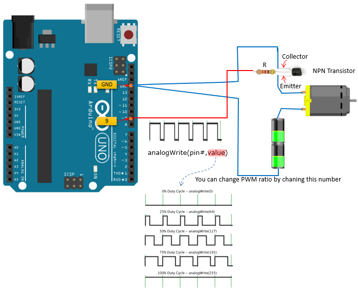
Now I hope you got the general idea on what PWM is and how it works. Then, how can we generate this kind of PWM signal with Arudio. In Arduino, it is supuer simple to generate the PWM signal.. it is almost as easy as turning on a LED. Pick any Arduino output pin that can support PWM and use the function analogWrite() function. In my example as shown below, I picked pin 9 as PWM output pin. Once you picked up a pin and connect a wire to an extern switching circuit, the only thing you have to do is just write a function like analogWrite(9, 100).
How to change the direction of motor spin ?
If you want to develop a motor system that needs to control the speed only (like fan) or a toy car that do only 'stop and go', PWM would be all you need for the system. However, if you want to make a motor system that should be able to change the direction of the spin (e.g, a car that can move forward and backward), you need to have some technique to change the direction of the spin. How can we do this ? The simple answer is to use H-Bridge (If you are not familiar with the concept of H-Bridge, refer to Electronics : H-Bridge page)
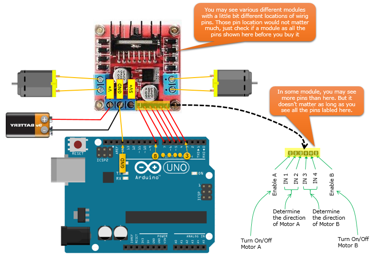
Following is an example circuit that I built using a H-bridge module. This H-bridge module use a chip called L298 (It would be good to study a little bit on how the chip works). In terms of functionality, this single chip has all the critical components for controlling two motors, but to use it in real practice you would need to add several other components (e.g, Kickback diodes, Capacitors and Regulators) and need to do pretty much of soldering work. Instead of doing all of these solderings and testing, I decided to purchase a ready-made module. Before I go to electronic shop, I watched a couple of YouTube videos and searched several tutorial pages and got some general idea on how the module look like and what kind of pins it provides. However, one problem was that the module in every tutorial looks similar but not exactly same. In some modules, number of Pins are different.. and in some module the position of the pins are different. When I was at the electronic shot, the module they were selling were not exactly same as any modules that I saw in the tutorials. But I bought the module int the shop anyway because it was the only module available there and fortunately it got all the pins and functions that I need and it worked OK. So, when you try to buy this module, don't worry too much if you don't get the exactly same module as shown below. Just check In/Out pins and see if the module has all the pins as shown below.
A the wiring is as shown above. Yes.. it was a lot of wiring .. The battery shown above is only to supply the power to the H-Bridge module. Some of the power from the battery will be used to operate the chip on the module and some of the power will be used to spin the motor. This battery is nothing to do with Arduino operation. One thing you should notice is that the ground pin on the module and Arduino board are connected. This is important to let both Arduino board and the module has same ground level. Another important thing to notice is how to assign Arduino pins to control the module. Here, I needed 6 pins to controls the two motors. Of course, you would need only three pins if you want to control only one motor. All 6 Arduino pins should be set as output pins and those pins connected to Enable A / Enable B pin should have PWM capability to control the speed of the motors. In my example, I used Arduino 3,4,5,6,7.8 pins connected as in the figure above.
Here I will show you a very simple code just to give you an idea on how you operate H-bridge module. It is not fancy at all and doing the very simple thing as follows. i) At first, the two motor spin in the same direction and same speed ii) Keep the sate of step i) for 5 sec iii) Stop the motor A (Motor on the left side). Motor B (Motor on the right side) keep running. iv) Keep the sate of step ii) for 3 sec v) Spin the motor A again at the same speed as Motor B
Following is the code for the steps listed above.
void setup() {
// As you see here, I set all the 6 pins as OUTPUT pinMode(5, OUTPUT); // IN3 pinMode(4, OUTPUT); // IN4 pinMode(3, OUTPUT); // Enable B
pinMode(6, OUTPUT); // IN2 pinMode(7, OUTPUT); // IN1 pinMode(8, OUTPUT); // Enable A
}
void loop() {
// Following three lines to operate Motor B (the one on right). The important to note that you have to set opposite // output level for IN3 and IN4 to spin the motor in any one direction. Which direction will it turn ? It depends on // how you connected your motor to the module. So just try and figure it out on your own. // If you want to change the direction, just change both level of IN3 and IN4 pin. // And then, I spin the motor by sending PWM signal via Enable B pin. digitalWrite(4, LOW); // IN4 digitalWrite(5, HIGH); // IN3 analogWrite(3, 180); // Enable B
// Following three lines to operate Motor A (the one on left). The important to note that you have to set opposite // output level for IN3 and IN4 to spin the motor in any one direction. Which direction will it turn ? It depends on // how you connected your motor to the module. So just try and figure it out on your own. // If you want to change the direction, just change both level of IN1 and IN2 pin. // And then, I spin the motor by sending PWM signal via Enable B pin. digitalWrite(6, LOW); digitalWrite(7, HIGH); analogWrite(8, 180);
// Now the two motors are running in the same direction and at the same speed
// Stay as it is for 5 sec delay(5000);
// Stop the Motor A by sending PWM 0 analogWrite(8, 0);
// Now Motor A stopped
// Stay as it is for 3 sec delay(3000);
// Spin the Motor A by sending PWM 180 (same speed as Motor B) analogWrite(8, 180);
}
Reference :
|
||