A UE far from the eNB sees the downlink later than a UE close to it, and its uplink also takes longer to travel back. If every UE simply transmitted on its own downlink timing, the uplink signals from different UEs would arrive at the eNB at different times and overlap. Timing Advance is the mechanism that fixes this, and it works in two steps.
I'll start with what Timing Advance is and how the MAC CE carries it. Then I'll convert a TA value into time, show where the first TA value comes from, and explain what the UE does when TA commands stop. The last section shows TA values from a live network.
- What is Timing Advance ?
- Timing Advance Command MAC CE
- How is a TA value converted into time ?
- Where does the first TA value come from ?
- What happens when the TA commands stop ?
- Example 1 - Timing Advance in a Live Network in the field
- Reference
What is Timing Advance ?
Let's start with the problem that Timing Advance solves. The eNB expects the uplink subframes of all UEs to arrive aligned with its own subframe timing, within the cyclic prefix. A UE cannot know its own round trip delay, so the eNB has to measure it and tell the UE.
Timing Advance is a MAC CE that is used to control Uplink signal transmission timing. Network (eNodeB in this case) keep measuring the time difference between PUSCH/PUCCH/SRS reception and the subframe time and can send a 'Timing Advance' command to UE to change the PUSCH/PUCCH transmission to make it better aligned with the subframe timing at the network side. If PUSCH/PUCCH/SRS arrives at the network too early, network send a Timing Advance command to UE saying "Transmit your signal a little bit late", If PUSCH/PUCCH/SRS arrives at the network too late, network send a Timing Advance command to UE saying "Transmit your signal a little bit early".
The advance that the UE applies is the round trip delay, not the one way delay. The downlink reaches the UE late by the propagation delay, and the uplink needs the same delay again to reach the eNB. So a UE at 1 km from the eNB needs an advance of about 6.7 microseconds, twice the 3.3 microseconds one way delay.
Timing Advance aligns uplink arrival at the eNB : the UE sends earlier so that its signal arrives on the eNB subframe boundary.The eNB measures, and the UE only applies : the eNB uses PUSCH, PUCCH or SRS to measure the error and sends the correction.The required advance grows with distance : it covers the round trip, about 6.7 microseconds for every km between the UE and the eNB.
Timing Advance Command MAC CE
Once the UE is connected, the eNB sends corrections in a MAC CE, one octet long. The octet has changed once, in Release 11, when carrier aggregation needed more than one uplink timing.
MAC PDU for Timing Advance is as follows. It is one byte data and the first two bits are reserved and set to be always 0. The remaining 6 bits carries Timing Advance command value ranging from 0 to 63.
As you see in the following figures, for Rel 8,9,10 there is no special tag for each component carrier, meaning that even in Carrier Aggregation single Timing Advanced value apply to all the component carriers. But in Rel 11, the first 2 bits are allocated to the TAG Id, which indicates the Timing Advance Group that the value is for. If TAG id is 0, it means it is for the TAG that contains the PCell.
< 36.321 Rel 8,9,10 - Figure 6.1.3.5-1: Timing Advance Command MAC control element >

The two leading bits are reserved, so one TA command applies to every uplink carrier.
< 36.321 Rel 11,12,13 - Figure 6.1.3.5-1: Timing Advance Command MAC control element >

The two leading bits now carry the TAG Id, so each Timing Advance Group gets its own correction.
- TAG Id : 2 bits, values 0 to 3. The TAG containing the SpCell has the TAG Identity 0, and 36.321 calls it the pTAG. The other TAGs are secondary TAGs, or sTAGs.
- Timing Advance Command : 6 bits, the index value TA = 0, 1, 2, ... 63. The next section converts it into time.
- Why TAGs exist : carriers in different bands can reach the eNB through different paths, for example through a repeater, so they may need different advances.
The two layouts have the same size, and only the meaning of the first two bits differs. A decoder therefore has to know the release and the configuration of the UE before it reads those bits.
The TA command is a relative correction : it moves the current timing forward or back by a small step, and it never gives an absolute value.TAG Id 0 is always the group with the PCell : a UE without secondary TAGs receives only TAG Id 0.Serving cells in one TAG share one uplink timing : 36.213 applies the same PUSCH and SRS timing to every secondary cell in the TAG.
How is a TA value converted into time ?
A 6 bit field can only carry 64 values, so each value has to stand for a fixed step of time. The step is 16 Ts, and the value 31 in the middle of the range means no change.
Then how to translate each value of TA(Timing Advance) value to physical 'time' delay or advance value. It is described in detail in 36.213 4.2.3 Transmission timing adjustments. Simply put, the UL transmit timing is controlled by following equation.
UL Transmission Time = (UL Transmittion Time for Previous subframe) + (TA value - 31) x 16 samples.
, where 1 sample is about 0.033 us and 16 samples is about 0.52 us.
By this calcuation, you can see that the maximum timing change by single TA value (0 or 63) is about 16.7 us (I hope my calculation is right. please let me know if this calculation is wrong).
Let's write the same equation the way 36.213 v19.4.0 clause 4.2.3 writes it. The UE keeps a value NTA, and a TA command TA updates it as NTA,new = NTA,old + (TA - 31) x 16. A positive change advances the uplink transmission, which means the UE transmits earlier. A negative change delays it. So the "UL Transmission Time" in the equation above is best read as the amount of advance, not as a clock time.
The calculation above is correct for TA = 63. That value gives (63 - 31) x 16 = 512 Ts, which is about 16.7 microseconds of extra advance. The value 0 gives (0 - 31) x 16 = -496 Ts, which is about 16.1 microseconds less advance. In distance, one step of 16 Ts is about 0.52 microseconds of round trip, or about 78 m between the UE and the eNB.
The UE does not apply a command at once. For a command received in subframe n, the adjustment applies from the beginning of subframe n+6. It applies from n+5 when the UE is configured with shortProcessingTime and the PDCCH is in the UE-specific search space.
TA = 31 means no change : values above 31 advance the uplink, and values below 31 delay it.One step is 16 Ts, about 0.52 microseconds : that is about 78 m of change in the distance between the UE and the eNB.One command moves the timing by at most about 16.7 microseconds : a larger change needs several commands, one after another.A command takes effect 6 subframes later : a log shows the new uplink timing from subframe n+6, not from the subframe of the command.
Where does the first TA value come from ?
The MAC CE only corrects a timing that already exists. Before the first uplink data, the UE has no NTA at all, so the first value has to come from the random access procedure.
The UE sends the PRACH preamble without any advance. The eNB measures when the preamble arrives, and returns an 11 bit Timing Advance Command in the Random Access Response. This field is absolute, not relative. It carries TA = 0, 1, 2, ... 1282, and the UE sets NTA = TA x 16.
The largest value is 1282 x 16 = 20512 Ts, which is about 0.67 ms of round trip. That corresponds to a distance of about 100 km, which is the largest cell radius the RAR can serve. When the UE is configured with an SCG, the range is only TA = 0 to 256.
36.211 v19.3.0 clause 8.1 then adds a fixed offset. The UE starts an uplink frame (NTA + NTA,offset) x Ts before the downlink frame, ignoring the NTN terms. NTA,offset is 0 for FDD and 624 Ts for TDD, which gives the eNB about 20 microseconds to switch from receive to transmit.
The RAR gives an absolute TA, and the MAC CE gives a relative one : the RAR sets NTA, and every later MAC CE adds to it.The 11 bit RAR field sets the cell size limit : 1282 steps of about 78 m give a cell radius of about 100 km.TDD adds a fixed 624 Ts : so the same NTA gives a larger total advance in TDD than in FDD.
What happens when the TA commands stop ?
A UE that moves keeps changing its round trip delay, so an old TA value slowly becomes wrong. The MAC therefore limits how long the UE may trust its uplink timing, with a timer per TAG called timeAlignmentTimer.
The UE starts or restarts timeAlignmentTimer every time it applies a TA command for that TAG, from a MAC CE or from a RAR. In 36.331 v19.3.0, the TimeAlignmentTimer IE takes the values sf500, sf750, sf1280, sf1920, sf2560, sf5120, sf10240 and infinity, in subframes. So the longest finite value is 10.24 seconds.
When the timer of the pTAG expires, the UE flushes all HARQ buffers and asks RRC to release PUCCH and SRS for all serving cells. It also clears configured downlink assignments and uplink grants, and considers every other timeAlignmentTimer expired. From then on, the UE may send only a Random Access Preamble on the uplink. So the next uplink data, or a scheduling request, has to start with a new random access procedure.
When the timer of an sTAG expires, the effect stays inside that TAG. The UE flushes the HARQ buffers, releases SRS and PUCCH, if configured, and clears the grants of the serving cells in that TAG only.
timeAlignmentTimer decides how long a TA stays valid : the eNB must send TA commands more often than the timer value to keep a UE aligned.Expiry of the pTAG timer ends all uplink except PRACH : the UE loses PUCCH and SRS, and has to perform random access again.infinity turns the check off : the UE then never considers its timing expired, which is safe only when the round trip delay does not change.
Example 1 - Timing Advance in a Live Network in the field
The sections above explain what the UE does with a TA value. This example shows what the values look like along a real drive route, where the UE changes its serving cell many times.
Following plot is from the data captured by a drive test tool Azenqos Drive Test tool (AZQ Android). I got the log captured by the tool and exported the data as csv file and then plot it on Microsoft Excel. The map displaying the path of the measurement shown at the bottom is the one automatically created by AZQ reporting tool. It is hard to interpret the exact meaning of each points unless you have the exact location of eNB displayed on the map and the distance between UE and the eNB is recorded, but at least you would see some interesting pattern of TA value changes as the UE moving along the path getting closer to and farther away from the serving eNB.
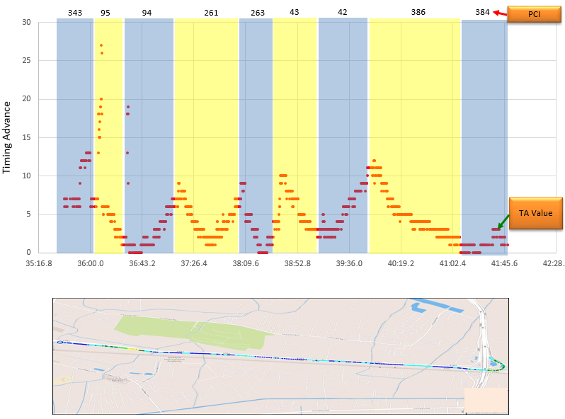
TA falls when the UE approaches the serving eNB and rises when it moves away, and it restarts from a new value after each cell change.
- Upper plot : Timing Advance on the vertical axis against time, from about 35:17 to 42:28. Each shaded band is one serving cell, labelled with its PCI at the top: 343, 95, 94, 261, 263, 43, 42, 386 and 384.
- Largest values : the highest points, about 26 to 27, appear at the start of the PCI 95 band. Most of the other values stay below 13.
- V shapes : in the PCI 261 band, TA falls from about 9 to 1 and then rises again to about 6. This is the pattern of a route that passes close to the eNB and then leaves it.
- Steady slopes : in the PCI 386 band, TA falls from about 12 to 2 over more than a minute, so the UE moves towards that eNB for the whole band.
- Lower map : the drive route drawn by the AZQ reporting tool. The eNB locations are not on the map, so the plot cannot be checked against a real distance.
The plot does not say which unit the tool uses for its TA value. If the value is in the RAR unit of 16 Ts, one step is about 78 m, and the peak of 27 is about 2.1 km from the eNB. A TA of 0 or 1 then means that the UE is within about 100 m of the antenna.
TA is a direct measure of distance to the serving eNB : its shape along a route tells you when the UE approaches or leaves a site.A jump at a cell change is normal : the new cell gives its own TA in the RAR of the handover, based on the distance to the new eNB.Small TA values point to a dense network : values below 13 in most bands mean serving cells within about 1 km, under the unit assumption above.
Reference
- 3GPP TS 36.211 v19.3.0 - clause 8.1, Uplink-downlink frame timing
- 3GPP TS 36.213 v19.4.0 - clause 4.2.3, Transmission timing adjustments
- 3GPP TS 36.321 v19.3.0 - clause 5.2, Maintenance of Uplink Time Alignment, and clause 6.1.3.5, Timing Advance Command MAC Control Element
- 3GPP TS 36.331 v19.3.0 - TimeAlignmentTimer