This page shows some correlation between Frequency Error and CRC Error. It is intuitive that you would get more CRC error if you have larger frequency error,but how much frequency error causes how much CRC error is largely physical layer performance implemented by chipset maker.
I'll first put the 3GPP limits in front of you, because the plots only make sense against them. Then we'll look at why a small frequency error breaks decoding at all, and finish with three chipsets measured in the same kind of test.
The page covers the following topics.
- Frequency Error Requirements
- Why does Frequency Error cause CRC Error ?
- Examples of Frequency Error and CRC Error
- Reference
Frequency Error Requirements
Before judging a plot, you need to know how large a frequency error the UE and the eNB are allowed to have. The limits are small, in the order of 0.1 ppm, so it helps to convert them to Hz at a real carrier frequency.
The acceptable frequency error specified by 3GPP is as follows. (The range is different between eNB and UE).
UE side frequency Error : It is defined in 36.521 6.5.1 Frequency Error. It is specifying the modulated frequency error with reference to received carrier frequency. It is supposed to be +/- 0.1 ppm. For example, if the received carrier frequency is 2.0 Ghz, the frequency error should be within the range of 2.0Ghz +/- 200 Hz. (200 = 2.0 * 10^9 * 0.1 *10^-6)
eNB side frequency Error : It is defined in 36.104 6.5.1 Frequency error. The error should be within +/- 0.05 ppm. For example, if the received carrier frequency is 2.0 Ghz, the frequency error should be within the range of 2.0Ghz +/- 100 Hz.(100 = 2.0 * 10^9 * 0.05 *10^-6)
Frequency Error at baseband : I haven't found any specification for the baseband frequency error. Also, theoretically there shouldn't be any error at the baseband.. but in reality there would be a certain degree of frequency at the baseband mainly because there would be some frequency error with Reference Clock for the baseband. For example, if the frequency error of baseband reference clock is +/- 0.05 ppm, there would be baseband frequency error for 15 Khz (one sub carrier) would be +/- 0.00075 Hz.
The core requirement for the UE is in 36.101 v20.0.0 clause 6.5.1. The UE modulated carrier frequency shall be accurate to within +/-0.1 PPM, observed over one time slot of 0.5 ms, compared to the carrier frequency received from the eNB. 36.521-1 clause 6.5.1 is the conformance test that checks this requirement on a test system.
Note the reference in that sentence. The UE is not measured against an absolute frequency. It is measured against the DL carrier it receives, so the UE is expected to lock to the eNB. This is why a UE with a good receiver can follow an eNB that is itself 0.05 ppm off.
At baseband, the error that matters in practice is the RF error. The UE usually derives its RF local oscillator and its baseband clock from the same reference oscillator. A carrier offset of 200 Hz therefore moves every subcarrier by 200 Hz at baseband, and that is the offset the receiver has to estimate and remove.
UE limit : +/-0.1 ppm : about +/-200 Hz at 2 GHz, relative to the received DL carrier, over one slot.eNB limit : +/-0.05 ppm : about +/-100 Hz at 2 GHz, as the page quotes from 36.104.The RF offset dominates : it shifts every subcarrier by the same amount at baseband.
Why does Frequency Error cause CRC Error ?
A frequency error of 200 Hz looks harmless next to a 15 kHz subcarrier spacing. Let's see why it can still produce CRC errors, because the plots below show errors even at smaller offsets.
The first effect is inter-carrier interference. The offset is 200 / 15000, about 1.3% of one subcarrier. The subcarriers are then no longer exactly orthogonal at the FFT output, and each one leaks a little energy into its neighbours. At 1.3% this leakage is small, and it mainly raises the noise floor.
The second effect is larger. A frequency offset rotates the phase of the received signal by 2 pi x offset x time, and the rotation keeps growing from symbol to symbol. At 200 Hz the phase moves by about 4.8 degrees during one useful symbol of 66.7 microseconds. It moves by about 20 degrees between OFDM symbols 0 and 4 of a slot, which carry the CRS for antenna ports 0 and 1 (36.211 v19.3.0 clause 6.10.1.2).
The UE estimates the channel from the CRS and interpolates it to the data REs in between. If the phase keeps turning between two CRS symbols, the interpolated estimate is wrong for the data symbols. The outer points of 64QAM tolerate less than 8 degrees of phase error, even without noise, before they cross into the next decision region. So a high MCS fails first, and the CRC error rate rises.
This also explains why the chipset matters so much. Every receiver estimates the offset and corrects it, for example from the CP or from the CRS, and a good estimator leaves only a few Hz. The CRC error rate therefore depends on the residual offset after correction, not on the raw offset. The Physical Layer Parameter - DL, FDD page gives the subcarrier spacing and symbol timing used above.
The phase error grows with time : about 20 degrees between CRS symbols 0 and 4 at 200 Hz.Channel estimation suffers first : interpolation between CRS symbols cannot follow a turning phase.High order modulation fails first : 64QAM corner points tolerate less than 8 degrees.Residual offset decides the CRC result : a good frequency tracking loop hides the raw offset.
Examples of Frequency Error and CRC Error
Now I will show you a couple of examples of how frequency error would be influencing on data decoding error. This is based on UE side frequency error, but same rule would apply to eNB side as well.
In all three plots, the red trace is the frequency error in Hz per subframe. The blue bars at the bottom mark the subframes with a NACK, which means a DL CRC error. The horizontal axis is time in ms.
Example 1 - errors spread over the whole test
In following plot, the red plot indicate the frequency error for each subframe and the blue bar(line) at the bottom indicate the location of the subframe where CRC error happened. You would notice that the frequency of CRC error goes higher as the range of frequency error goes larger.
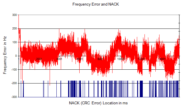
The frequency error swings between about -150 Hz and +200 Hz. NACKs become frequent once the swings grow.
First 4000 ms : the error stays mostly between -50 Hz and +100 Hz, and NACKs are rare.After about 4000 ms : the error moves in slow steps of more than 100 Hz in both directions, and NACKs appear in dense groups.Within the 3GPP limit : at a 2 GHz carrier, nearly all of the trace stays inside +/-200 Hz, so the UE can pass the frequency error test and still lose DL packets.
Example 2 - errors above a threshold until AFC
Following plot also shows the correlation between frequency error and CRC error. However, this is from a chipset from a different maker. First you would notice how drastically different the overal frequency fluctuation pattern depending on chipset makers.
In this graph, you see that a serious CRC error happens when the frequency error gets higher than a certain point (b) and CRC error disappears when the frequency error gets back to small value (c). (In this chipset, Automatic Frequency Correction was performed at point (c))
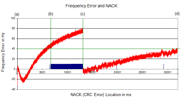
The error drifts upward from (a). NACKs run continuously from (b) to (c), and they stop when AFC returns the error to about 0 Hz at (c).
(a) to (b) : the error dips to about -25 Hz, then rises steadily with no NACK.(b) : at about 45 Hz, near the green line at 40 Hz, NACKs start and continue in every subframe.(c) : at about 75 Hz, AFC corrects the frequency, the error falls to about -5 Hz and the NACKs stop.(c) to (d) : the error drifts upward again toward 40 Hz, and single NACKs start to appear near the end.
For this chipset, the CRC errors start at about 45 Hz, which is far inside the 3GPP limit. The problem is not the size of the limit but the way the chipset tracks frequency: the AFC runs too late, after the drift has already broken decoding.
Example 3 - an ideal case
Following is an ideal case from another chipset maker. As you see, there is negligible amount of frequency error for the whole test span and as a result you don't see any CRC error over the whole period.
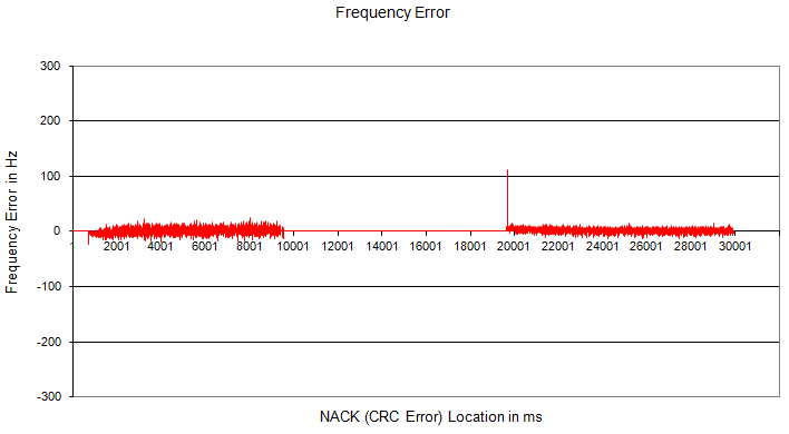
The error stays within about +/-20 Hz, and no NACK appears.
Two measured periods : about 0 to 9500 ms and about 19500 to 30000 ms, with no data in between.One spike : about 110 Hz at the start of the second period, with no NACK.Flat error : this chipset corrects the frequency continuously, so the drift never grows large.
Let's put the three examples side by side. The 3GPP limit was the same for all of them, but the results were very different.
The same test gives very different traces : the frequency tracking of the chipset decides the result.CRC errors can start far inside the limit : about 45 Hz in Example 2, against +/-200 Hz allowed at 2 GHz.Watch the drift, not only the value : slow drift before an AFC update is what caused the errors in Example 2.
Reference
- 3GPP TS 36.101 v20.0.0 - clause 6.5.1, Frequency error
- 3GPP TS 36.521-1 v19.2.0 - clause 6.5.1, Frequency error
- 3GPP TS 36.211 v19.3.0 - clause 6.10.1.2, Mapping of cell-specific reference signals to resource elements