PHICH stands for Physical channel HybridARQ Indicator Channel. Simply put, it is a secially designed downlink only channel which carries ACK or NACK for the PUSCH received by the network.
Uplink case they just used PUCCH for carrying ACK/NACK for each PDSCH it recieved. Why don't we use PDCCH for ACK/NACK on network side. Good topic for you to think over -:)
The PHICH answers one question for the UE after every PUSCH transmission: did the eNB decode it or not? The answer is a single bit, but many UEs need it in the same subframe, so the PHICH design is mostly about sharing a few REGs among many answers. The bullets below give the short version, and the sections that follow work through each step.
- PHICH is carried by the first symbol of each subframe when the PHICH duration is normal. (It is located in the same symbol as PCFICH).
- One PHICH is carried by multiple REG.
- Multiple PHICH can be carried by the same set of REG and these multiple PHICH being carried by the same REGs are called PHICH group. These multiple PHICHs are multiplexed by orthogonal codes.
- Therefore, to indentify a specific PHICH we need to know PHICH group number and orthogonal code index.
Followings are the topics to be covered in this page.
- Overall Channel Processing
- Multiplexing of PHICH
- What is PHICH Group
- PHICH Data Generation
- PHICH Data Mapping to Resource Elements
- Reference
Overall Channel Processing
How does one HARQ bit become a set of REs? The PHICH chain is short, but every step multiplies the size of the bit, so one ACK or NACK ends up as 12 REs with the normal cyclic prefix. The diagram below shows the five steps and the clause that defines each one.
The diagram below runs from the HARQ indicator HI at the top to the RE mapping at the bottom. Each yellow box names the operation and the 36.211 or 36.212 clause for it.

PHICH channel processing. Channel coding in 36.212 clause 5.3.5 and modulation, spreading, layer mapping and precoding in 36.211 clause 6.9. The last box cites clause 6.7.4, which is the PCFICH mapping; the PHICH mapping is 36.211 clause 6.9.3.
Step 1 repeats the HI bit three times: 111 for ACK and 000 for NACK. Step 2 maps the three bits to BPSK, and step 3 spreads each BPSK symbol with an orthogonal sequence of length 4, or 2 with the extended cyclic prefix. Step 3 also scrambles the result with a cell-specific sequence, initialised from the PCI in every subframe. Step 4 aligns the result to whole REGs and applies the transmit diversity precoding of the PBCH antenna ports. Step 5 places the symbol quadruplets in the REGs of the control region.
HI repeated 3 times : 111 for ACK, 000 for NACK.BPSK, then spreading by 4 or 2 : 12 symbols per PHICH with the normal cyclic prefix.RE mapping in 36.211 clause 6.9.3 : the diagram cites 6.7.4, the PCFICH clause.
Multiplexing of PHICH
In some (many ?) cases, mutiple PHICH can be mapped to a same set of resource elements and this group of PHICH being carried by the same set of resource element is called PHICH Group. (Why we have to carry multiple PHICH on a same set of resource elements ? Another good items for you to think -:) ).
When some "multiple things" are carried by the same physical resources, we call the multiple things being "multiplexed". So we can say a group of PHICH is being 'multiplexed' onto a set of resource elements.
When you multiplex something, you always have to think about how to "de-multiplex" them. It means that you have to multiplex somethings in such a way that they can be easily separated into individual things. If you multiplex things and those things cannot be demultiplexed, it is called a garbage -:).
One of the most common way of multiplexing in wireless communication would be to use "orthogoal sequences". (You may remember how they multplexed multiple set of data in CDMA or WCDMA). PHICH multiplexing also uses the same method, meaning they are multiplexed with a set of predefined orthogonal sequences. The set of orthogonal sequence defined in 3GPP 36.211("6.9 Physical hybrid ARQ indicator channel") is as follows.

36.211 Table 6.9.1-2. Eight sequences of length 4 for the normal cyclic prefix and four of length 2 for the extended cyclic prefix. The table is unchanged in v19.3.0.
You may notice that the PHICH spreading factor for 'Extended cyclic prefix' is half of the one for 'Normal cyclic prefix'.
The length of the sequence sets the size of the group. With the normal cyclic prefix, the 8 sequences of length 4 give 8 PHICHs per group. Sequences 0 to 3 use real values, and sequences 4 to 7 are the same patterns multiplied by j. With the extended cyclic prefix, only 4 sequences exist, so a group holds 4 PHICHs, and the formula in the next section doubles the number of groups to make up for it.
Orthogonal sequences separate the PHICHs of one group : 36.211 Table 6.9.1-2.8 PHICHs per group with the normal cyclic prefix : 4 real and 4 imaginary sequences of length 4.4 PHICHs per group with the extended cyclic prefix : sequences of length 2.
What is PHICH Group
As mentioned above, multiple PHICH data can be located in the same physical locations (in the same REs). This multiple PHICH that are multiplexed in the same location is called 'PHICH group'. How many PHICH can belong to a single PHICH group is determined by a parameter from higher layer (phich-Resource IE in MIB) and also determined by whether it is FDD or TDD. In case of TDD, this varies depending on subframe configuration.

36.211 clause 6.9. A PHICH resource is the index pair of the group number and the sequence index.
In FDD, PHICH group can be calculation as follows :

36.211 clause 6.9, number of PHICH groups for frame structure type 1. In v19.3.0 the same formula also covers frame structure type 3, the LAA frame structure.
In TDD, PHICH group can be calculation as follows :

36.211 Table 6.9-1: The factor mi for frame structure type 2

36.211 Table 6.9-1. The factor mi scales the number of groups per subframe in TDD. A value of 0 marks a subframe with no PHICH resources.
You would quickly notice that number of PHICH group is twice as many for extended cyclic prefix as the one for normal cyclic prefix.
You would see that to calculate the N_group_PHICH you should know Ng value and the specification says the Ng value comes from higher layer. In this case, the higher layers means "MIB (Master Information Block)". MIB has an IE(information element) called "phich-Resource" as shown below. This IE represents Ng.
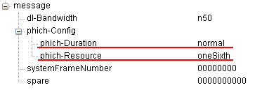
A MIB capture: dl-Bandwidth n50, phich-Duration normal and phich-Resource oneSixth. These two values fix the number of PHICH groups in the cell.
How many PHICHs can be carried by one PHICH group ? Maximum 8 PHICHs can be multiplexed into a PHICH group when we use normal CP and Maximum 4 PHICHs can be multiplexed into a PHICH when we use the extended CP. Zero PHICH in a PHICH group is also allowed. When multiple PHICHs get multiplexed, they use a certain length of orthogonal code. In case of normal CP, the length of the orthogonal code is 4 and in case of extended CP, the length is 2.
How many PHICH groups can be supported by a system bandwidth ? This can be determined by the system bandwidth (N_RB) and a special parameter called Ng. These N_RB and Ng value is carried by MIB as shown above.
With Ng and the N_DL_RB (maximum number of RB for a system bandwidth), you can calculate the N_group_PHICH as in the following table.
|
N_RB \ Ng |
1/6 |
1/2 |
1 |
2 |
|
6 (1.4 Mhz) |
1 |
1 |
1 |
2 |
|
15 (3 Mhz) |
1 |
1 |
2 |
4 |
|
25 (5 Mhz) |
1 |
2 |
4 |
7 |
|
50 (10 Mhz) |
2 |
4 |
7 |
13 |
|
75 (15 Mhz) |
2 |
5 |
10 |
19 |
|
100 (20 Mhz) |
3 |
7 |
13 |
25 |
Each PHICH in a PHICH group is mapped to each UE.
How many REG would be required to carry one PHICH ? To figure this out, we have to go through several steps and do some mental calculation.
i) ACK and NACK is encoded by 3 bits (111 for ACK, 000 for NACK).
iii) According to Table 6.9.1-2 of 36.211, each bit of PHICH is spreaded by 4 bits (SF=4) when we use 'normal cyclic prefix'. So each PHICH after spreading with a 4 bits orthgonal sequence becomes 12 bits.
iii) PHICH is modulated in BPSK and this means 'one symbol carries one bit'. And this in turn means we need 12 symbols for each PHICH (each ACK or NACK).
iv) Each RE (Resource Elements) carries one symbol. So we need 12 REs to carry one PHICH (one ACK or NACK).
v) one REG is made up of 4 REs. So we need 3 REGs to carry one PHICH.
vi) These three REGs for one PHICH is distributed evenly across the whole bandwidth.
From those multiple Groupes in a system bandwith and multiple PHICHs within each PHICH group, how UE would know exactly which PHICH to look for ? For the very details, you have to understand the procedure described in 9.1.2 PHICH Assignment Procedure of 36.213. As I mentioned above, you have to know the PHICH group number and orthogonal sequence index to locate the specific PHICH. UE figure out these two numbers from the lowest PRB index of the first slot of the PUSCH transmission and DMRS cyclic shift.
The table above follows from the formula for the normal cyclic prefix, ceil(Ng x NRB/8), and every entry checks against it. The MIB capture above gives a worked case. With n50 and oneSixth, NPHICHgroup = ceil(50/48) = 2, so this cell has 2 PHICH groups and room for 16 HARQ answers per subframe. Each group takes 3 REGs, so the PHICH uses 6 REGs, or 24 REs, of the control region.
36.213 v19.4.0 clause 9.1.2 gives the index pair. The group is nPHICHgroup = (IPRB_RA + nDMRS) mod NPHICHgroup + IPHICH NPHICHgroup, and the sequence is nPHICHseq = (floor(IPRB_RA / NPHICHgroup) + nDMRS) mod 2NSFPHICH. IPRB_RA is the lowest PRB of the PUSCH in the first slot, and nDMRS comes from the cyclic shift field of the uplink DCI. IPHICH is 1 only for TDD configuration 0 with PUSCH in subframe 4 or 9, so for FDD the last term drops out.
In the cell of the capture, a PUSCH starting at PRB 10 with nDMRS = 0 gets group 10 mod 2 = 0 and sequence floor(10/2) mod 8 = 5. A second UE starting at PRB 11 gets group 1 and the same sequence 5, so the two answers never collide. Two UEs that start on the same PRB, as in uplink MU-MIMO, need different nDMRS values to reach different PHICH resources. For FDD, the answer comes in subframe n + 4 for a PUSCH in subframe n.
NPHICHgroup = ceil(Ng x NRB/8) : doubled for the extended cyclic prefix.n50 with oneSixth gives 2 groups : 16 PHICHs in 6 REGs.Group and sequence come from the lowest PRB and nDMRS : 36.213 clause 9.1.2.IPHICH = 1 only in TDD configuration 0 : subframes 4 and 9.
PHICH Data Generation
The two formulas below turn the three coded bits into the symbols that are mapped to REs. They are where the orthogonal sequence and the cell-specific scrambling enter, so they explain why PHICHs of one group can be separated while PHICHs of neighbouring cells look like noise.
Step 1 : Generation of d( )

Generation of d(i). The BPSK symbols z come from 36.211 Table 7.1.1-1, and each is repeated NSFPHICH times, multiplied by w and by the scrambling term 1 - 2c(i).
The formula is d(i) = w(i mod NSFPHICH) (1 - 2c(i)) z(floor(i / NSFPHICH)). The index floor(i / NSFPHICH) repeats each BPSK symbol over one full sequence, so Msymb = NSFPHICH x Ms = 4 x 3 = 12 with the normal cyclic prefix. The scrambling sequence c(i) starts from cinit = (floor(ns/2) + 1)(2NIDcell + 1) 29 + NIDcell, which changes with the subframe and the PCI.
Step 2 : Generation of y( )

Resource group alignment, layer mapping and precoding. With the extended cyclic prefix, c = 2 pads the sequence so that two groups share one mapping unit.
With the normal cyclic prefix, the 12 symbols already fill 3 REGs, so the alignment step changes nothing. With the extended cyclic prefix, each PHICH has only 6 symbols, and the alignment interleaves two groups into one set of 3 REGs. Layer mapping and precoding then follow the transmit diversity rules of the antenna ports that also carry the PBCH, so the PHICH needs no extra antenna configuration.
d(i) = w x (1 - 2c(i)) x z : spreading and cell-specific scrambling.12 symbols per PHICH with the normal cyclic prefix : 4 x 3.Extended cyclic prefix pairs two groups : c = 2 in the alignment step.
PHICH Data Mapping to Resource Elements
The detailed procedure described in 36.211 6.9.3 Mapping to Resource Element is explained in a pretty complicated manner. So I want to simplify the overall process with a specific condition of FDD and Normal Cyclic Prefix case.

PHICH mapping to REs. The groups are summed, split into symbol quadruplets and placed in three REGs per mapping unit. The note that l' is always 0 holds for the normal PHICH duration, not for every FDD cell with the normal cyclic prefix.
The mapping loop runs over the PHICH mapping units m', one per group with the normal cyclic prefix. Each unit places its three quadruplets i = 0, 1 and 2 in REGs spaced about a third of the band apart, starting from an offset of NIDcell x nl'/n1. The REGs are counted after the PCFICH REGs are removed, so the PHICH never collides with the PCFICH. The spread across the band gives each PHICH frequency diversity, and the PCI offset keeps neighbouring cells from using the same REGs.
The time index l' depends on the PHICH duration in the MIB. With the normal duration, all three REGs of a group sit in symbol 0. With the extended duration, quadruplet i goes to symbol i, so a group spans symbols 0, 1 and 2, and the control region must be at least 3 symbols long. 36.211 v19.3.0 Table 6.9.3-1 limits the extended duration to 2 symbols in MBSFN subframes and in TDD subframes 1 and 6.
Three REGs per group, spread across the band : offset by the PCI.PCFICH REGs are removed first : no collision with the PCFICH.Normal duration puts the PHICH in symbol 0 : extended duration spreads it over 3 symbols.
Reference
[2] 3GPP TS 36.211 v19.3.0 - clause 6.9, Physical hybrid ARQ indicator channel, and Table 6.9.3-1, PHICH duration
[3] 3GPP TS 36.212 v19.3.0 - clause 5.3.5, Channel coding of HI
[4] 3GPP TS 36.213 v19.4.0 - clause 9.1.2, PHICH assignment procedure