The Uplink slot structure looks as follows. When I was first reading LTE materials, almost every books and article says "LTE use SC(Single Carrier) FDMA for uplink signal" and because of the word 'Single Carrier' made me so confused about creating any images of Uplink slot structure. Even now I don't think I can explain clearly about 'SC FDMA'. You may ask to FPGA or DSP engineer about the details of SC FDMA mechanism.
- Slot Structure
- PUCCH RS
- PUCCH
- PUSCH RS
- PUSCH
- SRS
- Uplink Resource Grid
- Channels in Communication
- Gallery
- Reference
Slot Structure
But anyway good thing to me was that the most important factors in uplink slot is same as the one in the downlink. Just take a look at the overall uplink slot structure.
< LTE FDD Uplink Frame Structure >

- The picture is one subframe. Two slots of seven symbols each run left to right, and the system bandwidth in resource blocks runs up the left edge.
- PUSCH fills the middle of the band. The grey column in the middle of each slot is PUSCH RS, and 36.211 puts it on symbol 3 of the slot.
- PUCCH sits in the thin bands along the top and the bottom. Those are the highest and the lowest resource blocks of the carrier.
- SRS takes the last symbol of the subframe and spreads across the band. The note at the upper right says it is not there in every subframe.
One thing is missing from the front of the subframe, and its absence is the real difference from the downlink. A downlink subframe reserves its first one to four symbols for control. An uplink subframe reserves nothing, because uplink control is separated in frequency instead.
That is why the channels look localized. PUCCH is pushed to the two band edges. A UE sending control and a UE sending data then share the same symbols without colliding, and the reference signals are separated in time instead.
A slot holds seven symbols with normal cyclic prefix : 36.211 Table 5.2.3-1 gives six with extended cyclic prefix.Uplink control is separated in frequency : PUCCH takes the band edges, where the downlink takes the first symbols of the subframe.One symbol per slot goes to the reference signal : the receiver needs the channel estimate before it can demodulate anything else.SRS costs the last symbol of the subframe : and only in the subframes the network configures for it.
As in downlink, Frame time and slot time in Uplink is the same as in the downlink. And the resource block structure is also same both in uplink and downlink. As shown above, 7 symbols in one slot is also the same in both uplink and downlink.
A little bit of differences you would notice would be the location of the each channel. Normally in downlink case, a channel tend to lie across the whole bandwidth but the channels in the uplink slot seems to be more localized. For example, PUCCH is located only at the lowest and highest end in frequency domain and reference signals also localized in time domain or both timedomain and frequency domain.
PUCCH RS
Carries the Reference Signal that is required for demodulating PUCCH. It means if this part is not properly configured or eNodeB failed to detect this part, eNodeB cannot decode PUCCH.
The position of that reference signal changes with the PUCCH format. 36.211 Table 5.5.2.2.2-1 fixes a position per format, and the numbers below are the symbol indices within a slot.
PUCCH format |
Normal cyclic prefix |
Extended cyclic prefix |
1, 1a, 1b |
2, 3, 4 |
2, 3 |
2, 3 |
1, 5 |
3 |
2a, 2b |
1, 5 |
not applicable |
4, 5 |
3 |
2 |
The pattern in that table is a trade against payload. Formats 1, 1a and 1b carry two bits at most, so three of the seven symbols can go to the reference signal. Formats 2 and 3 carry twenty bits or more, so only two symbols are left for it.
The empty cell is not an oversight. Clause 5.4 states that formats 2a and 2b are supported for normal cyclic prefix only. There is no extended cyclic prefix position to give.
The reference signal position follows the format : three symbols for the small formats, two for the large ones.More payload means fewer pilots : a format carrying twenty bits cannot spend three of seven symbols on the channel estimate.Formats 2a and 2b are normal cyclic prefix only : which is why their extended column has no entry.A failed reference signal loses the whole format : the payload is small, so there is nothing left to decode it with.
PUCCH
PUCCH is where uplink control goes when there is no PUSCH to carry it. A UE with nothing to send still has to acknowledge downlink data and report what the channel looks like.
This channel can carries a lot of information (UCI), but depending on the configuration it can carry only a few of the following information.
- ACK/NACK for the recieved PDSCH data
- CQI
- RI
- PMI
As you see in the slot structure, PUCCH is located in the either extreme ends of the uplink frequency domain in alternating fashion between the two slots within a subframe, meaning that if the PUCCH is the lowest part of frequency domain in slot 0(first slot) and it will be located in the higest part of frequency domain in slot 1 (second slot). Exactly how many resource elements is allocated to the PUCCH is determined by network and the configuration is broadcasted to UE via SIB2.
For the details of PUCCH (Format, Location etc). Refer to the following sections in Quick Reference Page.
The page links to two of the formats above. 36.211 Table 5.4-1 lists nine, and the later ones exist because the amount of control a UE has to send grew with carrier aggregation.
PUCCH format |
Modulation scheme |
Bits per subframe |
1 |
not applicable |
not applicable |
1a |
BPSK |
1 |
1b |
QPSK |
2 |
2 |
QPSK |
20 |
2a |
QPSK+BPSK |
21 |
2b |
QPSK+QPSK |
22 |
3 |
QPSK |
48 |
4 |
QPSK |
depends on the allocated bandwidth |
5 |
QPSK |
depends on the allocated bandwidth |
Format 1 is the exception, and its two empty cells say why. It carries no modulated bits at all. 36.211 states that the information is carried by the presence or absence of the transmission, which is all a scheduling request needs.
Two further rules matter to the frame structure. PUCCH and PUSCH may be sent at the same time by one UE, but only if higher layers enable it. And in frame structure type 2, PUCCH is never transmitted in the UpPTS field.
Nine formats, not two : the page covers 1/1a/1b and 2/2a/2b, and 36.211 adds 3, 4 and 5.Format 1 sends no bits : the presence or absence of the transmission is the message.Capacity climbs from 1 bit to 48 and beyond : formats 4 and 5 scale with the bandwidth they are given.PUCCH is never sent in UpPTS : in TDD the special subframe carries no PUCCH.
PUSCH RS
Carries the Reference Signal that is required for demodulating PUSCH. It means if this part is not properly configured or eNodeB failed to detect this part, eNodeB cannot decode PUSCH. This is always located at the center of Uplink slot.
The specification is exact about the center. 36.211 maps the PUSCH demodulation reference signal to symbol 3 of the slot for normal cyclic prefix, and to symbol 2 for extended. Symbols run 0 to 6, so symbol 3 is the middle one.
A pilot in the middle shortens the worst case. The receiver measures the channel once and applies it to the symbols on both sides. No symbol is then more than three away from the measurement, where a pilot at the slot edge would leave six.
The reference signal covers only the resource blocks the UE was granted. It is not a cell-wide signal like the downlink cell specific reference signal, and it is present whenever the UE transmits PUSCH at all.
Symbol 3 of every slot : 36.211 gives symbol 2 instead when extended cyclic prefix is configured.The middle is the cheapest place for it : the channel estimate is carried at most three symbols in either direction.It spans the grant, not the carrier : only the resource blocks the UE is using carry it.It costs one symbol in seven : roughly fourteen per cent of the slot buys the channel estimate.
PUSCH
Carries Uplink data that UE tries to send. and it can also carries ACK/NACK for the PDSCH the UE recieved in addition to uplink data.
PUSCH takes what the other three leave. The band edges belong to PUCCH. Symbol 3 of each slot belongs to the reference signal, and the last symbol of the subframe may belong to SRS. Everything else can be granted.
The grant arrives on the downlink. DCI format 0 on PDCCH names the resource blocks, the modulation and coding scheme, and the power correction. The UE then transmits one subframe of PUSCH in response.
36.211 Table 5.3.2-1 gives the modulation schemes: π/2 BPSK, QPSK, 16QAM, 64QAM and 256QAM. The scheme is not fixed for the channel, and the scheduler chooses it for each grant from what the radio conditions will carry.
The antenna port numbering is worth noticing, because it is not the downlink numbering. 36.211 Table 5.2.1-1 gives PUSCH port 10 with one port configured, ports 20 and 21 with two, and ports 40 to 43 with four. PUCCH uses port 100, or ports 200 and 201.
PUSCH is the remainder : it fills whatever PUCCH, the reference signal and SRS have not claimed.Every transmission needs a grant : DCI format 0 carries the resource blocks and the modulation and coding scheme.Five modulation schemes are defined : from π/2 BPSK up to 256QAM, chosen per grant.Uplink antenna ports start at 10 : PUSCH uses 10, 20 and 21, or 40 to 43, and PUCCH uses 100, or 200 and 201.
SRS
SRS is the sounding reference signal, and it is the one uplink signal a UE sends without having data to send. The network uses it to measure a channel the UE is not currently transmitting on.
Refer to SRS in Quick Reference
That purpose explains its place in the frame. A scheduler needs to know what the whole band looks like to a UE before it picks resource blocks. Data transmissions only report the blocks already granted, so something has to cover the rest.
The slot structure figure near the top of this page shows where it goes. SRS occupies the last symbol of the subframe and spreads across the band. That position costs every UE the same, and it collides with no reference signal inside a slot.
It is not in every subframe. The same figure carries a note saying so, and 36.211 makes the subframes that carry SRS a cell configuration. The bandwidth it covers is configured too, by a cell-wide parameter and a UE-specific one together.
SRS shares its antenna port numbering with PUSCH, so the same ports 10, 20 and 21, or 40 to 43 apply. The linked page above covers the sequence and the hopping; what matters here is the symbol it costs.
SRS is sent without a data grant : it exists so the scheduler can measure blocks the UE is not using.It takes the last symbol of the subframe : one position for every UE, clear of the reference signals inside the slots.It appears only in configured subframes : the slot structure figure near the top of this page marks that with a note.Its bandwidth is configured twice : a cell-wide setting and a UE-specific one together decide how much of the band it sounds.
Uplink Resource Grid
Getting into details, Uplink resource has also a kind of Grid format as shown below. Try to familiar with parameter name in this figure since this parameter will be used in all the other part of the specification. If you are not familiar with these parameter, you would not be able to visualize the contents when you are reading other parts of the specification.
As you see, the smallest unit is 'Resource Element(RE)' and the smallest resource allocation unit is RB(Resource Block) which spans 7 REs along time domain and 12 REs along frequency domain. It means one RB has 84 REs (7 x 12) in it.
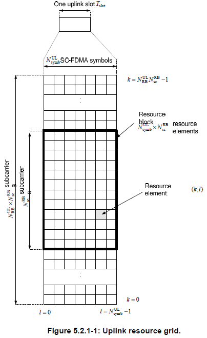
- The horizontal axis is l, the SC-FDMA symbol index. It runs from 0 at the left to NsymbUL minus 1 at the right.
- The vertical axis is k, the subcarrier index. It runs from 0 at the bottom to NRBUL times NscRB minus 1 at the top.
- The heavy rectangle is one resource block, and the figure labels it NsymbUL times NscRB resource elements.
- A resource element is the pair k and l: one subcarrier in one symbol.
36.211 Table 5.2.3-1 fills in two of those three numbers. NscRB is 12 whichever cyclic prefix is used. NsymbUL is 7 for normal cyclic prefix and 6 for extended.
The specification then states the size in plain units. One uplink resource block is one slot in the time domain and 180 kHz in the frequency domain. That is 12 subcarriers at 15 kHz, and it is the same width as a downlink resource block.
The third number is the one that varies. NRBUL depends on the uplink transmission bandwidth configured in the cell, and 36.101 gives the values a cell may use. Nothing else in the grid changes with bandwidth.
k and l are the only two indices : one for the subcarrier and one for the symbol, and the pair names a resource element.k counts upward from the bottom : the figure puts k equal to 0 at the low edge of the band.A resource block is 180 kHz by one slot : 12 subcarriers at 15 kHz, the same as the downlink.Only the number of resource blocks moves : the cyclic prefix sets the symbol count and the rest is fixed.
Channels in Communication
Following diagram shows overall sequence of Uplink/Downlink data transmission. You would be able to associate the data transmission sequence diagram and the specific location of each channels in DL/UL frame structure.
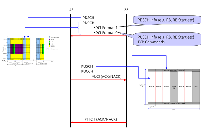
- The two vertical lines are the endpoints. The UE is on the left and the SS, the system simulator standing in for the network, is on the right.
- The top arrow runs downward and carries PDCCH and PDSCH together. DCI format 1 describes the downlink assignment and DCI format 0 the uplink grant.
- The middle arrow runs upward and carries PUSCH and PUCCH, with the UCI holding the acknowledgement for the downlink data.
- The bottom arrow runs downward again and is PHICH, which acknowledges the uplink data the UE just sent.
- The two insets are the grids themselves, the downlink map on the left and the uplink slot structure on the right.
One label in the picture is a slip. The callout beside DCI format 0 reads TCP Commands, and the field is the TPC command. 36.212 gives DCI format 0 a two bit TPC command for the scheduled PUSCH, which corrects the UE transmit power.
The diagram draws a loop, and that loop is why the uplink grid looks as it does. Every uplink transmission answers a downlink message, and every downlink transmission is answered on the uplink. PUCCH carries that answer when there is no PUSCH to put it in.
Every uplink transmission is scheduled : DCI format 0 on PDCCH arrives before the PUSCH it grants.Acknowledgements travel both ways : UCI on PUCCH or PUSCH going up, PHICH coming down.The callout should read TPC : 36.212 gives DCI format 0 a two bit transmit power control command.PUCCH exists for the subframes with no grant : the answer still has to reach the network.
Gallery
The capture below is the slot structure again, with the constellation of every symbol drawn beside it. One plot in each row does not look like the others, and the difference is worth understanding.
< LTE FDD Uplink Frame Structure - Constellation >
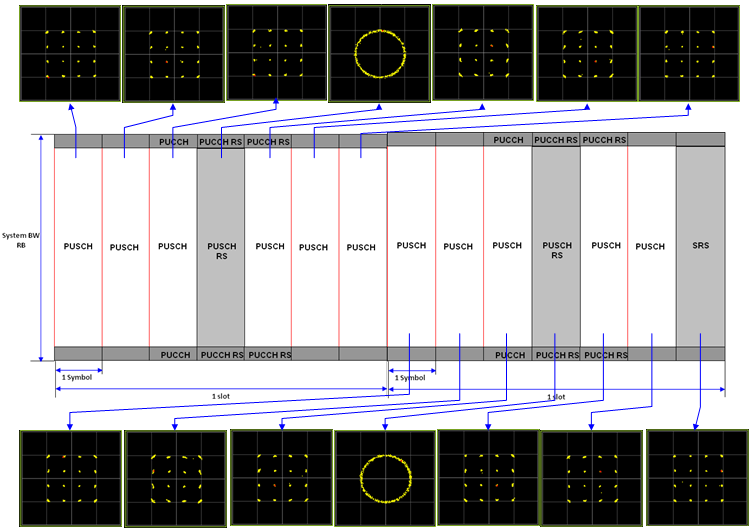
- Most of the plots are a cluster of points arranged in a square. That is what a data symbol looks like, and the number of points is the modulation order.
- One plot in each row is a ring instead. Every point sits at the same distance from the center and only the angle changes.
- The ring is the reference signal symbol. Its sequence has constant amplitude by construction, so the whole symbol lands on one circle.
That difference is useful on a real analyzer. A constant amplitude sequence keeps the peak to average ratio low. That is the same reason the uplink uses a transform precoded waveform at all.
It is also the quickest way to find the reference signal in a capture. The ring needs no decoding and no configuration to recognize, so it locates symbol 3 of the slot by eye.
A ring means a reference signal : constant amplitude and changing phase, which no data symbol produces.A square cluster means data : and counting the points gives the modulation order.Constant amplitude is deliberate : it keeps the peak to average ratio down, which matters more in the uplink than in the downlink.The ring locates the slot : finding it fixes symbol 3, and the slot boundary follows.
Reference
[1] 36.211 : 3GPP - E-UTRA; Physical channels and modulation, v19.3.0. Clause 5.2 and Figure 5.2.1-1 give the uplink resource grid, Table 5.2.1-1 the antenna ports, and Table 5.2.3-1 the resource block parameters. Table 5.4-1 lists the PUCCH formats, Table 5.5.2.2.2-1 the PUCCH reference signal positions, and clause 5.5.2.1.2 the PUSCH one.
[2] 36.212 : 3GPP - E-UTRA; Multiplexing and channel coding, v19.3.0. The DCI format 0 field list is the source for the TPC command quoted above.