There are many cases where we have to seriously consider 'Error'. Actually in almost every data processing and communications error handling is one of the most critical part of the process.
Several common examples of the case where some form of error handling is used are as follows :
- Data Storage and read on Memory, Harddisk, CD etc
- Serial Communication (RS 232)
- IP Communication
- Most of Wireless Communication (e.g, Mobile Communication like WCDMA, LTE etc)
You would realize that most of digital data processing or communication would have not be realized if there is no mechism for error handling (error detection and correction)
Followings are the topics that will be dealt in this page.
- What is Error ?
- What is Error Detection ?
- What is Error Correction ?
- Error Detection/Correction Techniques
- How do the four techniques compare ?
- What is done if the reciever find the error ?
- What do LTE and NR actually use ?
What is Error ?
First let's think of the definition of 'Error'. What is 'Error' ? It is simple. Error can be defined as 'any difference between the transmitted data and received data'. This may sound specific only to communication. In case of data storage, you can define Error as 'any difference between the data being sent for writing and the data really written on a media (e.g, Hard Disk, Memory or CD).'

Figure 1. An error is any difference between the two bit streams. Exactly one bit has flipped here, and nothing in the received data by itself tells the receiver which bit it was.
Let's look at where those flipped bits come from, because the cause shapes every technique further down this page. On a radio link the usual causes are thermal noise, interference from another transmitter, and fading that drops the received power for a few symbols. On a wire the causes are crosstalk and electrical transients. In storage they are media defects and charge leakage. The mechanisms are different, and the result on the data is the same.
Two patterns are worth separating, and much of this page depends on the difference. A random error hits single bits that are spread out, and each bit flips independently of its neighbours. A burst error hits a run of consecutive bits at once, which is what a deep fade or a scratch on a disc produces. A technique that handles one pattern well often handles the other badly. Two dimensional parity locates a single random error exactly, and a burst defeats it as soon as the burst crosses one whole row.
Engineers put numbers on this with BER and BLER. Bit Error Rate is the fraction of bits that arrive wrong. Block Error Rate is the fraction of blocks that arrive with at least one wrong bit, and LTE and NR schedulers work to a BLER target rather than a BER target. The two are not interchangeable. A BER of 10-3 on a 1000 bit block gives a BLER near 63%, because one bad bit spoils the whole block.
An error is a difference, and nothing else : the definition says nothing about the cause. Noise, interference and a bad disc sector all produce the same thing, which is why one detection scheme can serve all of them.Random and burst errors need different defences : ask which pattern a link produces before choosing a scheme. Interleaving exists for exactly this reason, because it turns a burst into something that looks random to the decoder.BLER is the number a scheduler actually targets : LTE and NR aim at about 10% BLER on the first transmission and let HARQ recover the rest. A BER figure on its own will not tell you whether that target is met.
What is Error Detection ?
Once Error happened, we need to have some mechanism to figure out 'whether there exists any error' or 'exactly where is the error occured'. This mechanism of finding the existence of error is called 'Error Detection'. If we know the exact contents of transmitted data, it would be very simple to find out the location of errors. Just simply by comparing the transmitted data and received data, we can easily find the location of errors. However in realty, we don't know what is the transmitted data (original data). So we have to figure out the location of errors only from the received data. This is why Error detection is not so simple.

Figure 2. Detection answers the yes-or-no question. Some mechanisms also give the position of the error and some do not, and that split is what separates the two types of detection.
There are roughly two types of Error Detection as follows.
- A mechanism that tells on the existence of error, but does not tells on the location of errors.
- A mechanism that tells on both the existence of error and the location of errors.
Of course, the second type is better in most case since it will give a chance for error recovery. But in most cases, this second type tend to be more complicated to be implemented or requires more overhead for data transfer. This is why the first type of mechanism is still being used in many applications.
One property matters as much as that split, and the two types above do not mention it. No detector catches everything. Every detection scheme maps many different received blocks onto the same check value, so some error patterns pass the check and the receiver declares a bad block good. The probability of that happening is the undetected error rate, and it is what really separates a weak scheme from a strong one.
A single parity bit shows the problem at its worst. It catches every odd number of flipped bits and misses every even number, so two errors in one block always pass. A 24 bit CRC is a different proposition. It leaves roughly one block in 224 undetected for random errors, which is about one in 17 million, and it catches every burst shorter than 24 bits outright. That gap explains why a mobile system spends 24 bits on a job a single bit could attempt.
Detection is a test, not a guarantee : a passing check means the receiver found no evidence of an error. It does not mean the block is clean, and the difference matters once you are investigating a rare failure.Knowing where costs more than knowing whether : the second type of mechanism carries enough structure to point at a position, and that structure is extra overhead on every block you ever send.Burst length is part of the specification : a CRC of n bits catches every burst shorter than n bits. That guarantee is usually why a particular length was chosen, rather than the random error rate.
What is Error Correction ?
What is Error Correction ? The definition is simple.. (only Algorithm is complicated :). Definition of Error Correction is to fixing the error bit (data) to normal bit (data).

Figure 3. Correction needs more than detection. It needs the position of the wrong bit, and a code supplies that position only if it carries enough redundancy to point at it.
So correction needs a location, and that raises the obvious question. Where does the location come from, when the receiver never sees the transmitted data? The answer is redundancy, arranged so that the legal codewords sit far apart from one another.
Think of it as distance. A code maps k data bits onto n transmitted bits, so only 2k of the 2n possible patterns are legal codewords. The minimum Hamming distance d is the smallest number of bit positions in which two legal codewords differ. The decoder receives a pattern that is not a codeword and picks the nearest codeword instead. That guess stays safe while the errors have moved the pattern less than half the distance to a different codeword.
Two rules follow from that, and both are worth remembering. A code of minimum distance d detects up to d - 1 errors. The same code corrects up to (d - 1) / 2 errors, rounded down. Detection therefore costs about half as much as correction for the same code. A single parity bit is the smallest example: d is 2, so it detects one error and corrects none.
You pay for all of this in code rate, R = k / n. A rate 1/3 code sends three bits for every bit of data, so two thirds of the transmission carries no user data at all. The designer trades that overhead against the number of errors the link has to survive. LTE and NR re-make the trade on every transmission, and that is what adaptive modulation and coding does.
Correction is detection plus an address : every correcting scheme first has to work out which bits are wrong. A scheme that only says yes or no can never correct anything, whatever its overhead.Minimum distance sets both limits : d - 1 errors detected, and half that many corrected. Every claim a code makes about its strength comes from this one number.The overhead is the code rate, and it is never free : more correcting power means a lower R and fewer user bits per transmission. This is the trade a link adaptation algorithm is making on your behalf.
Error Detection/Correction Techniques
Whatever you do, there is no way to prevent any error. The only thing you can do for those errors is to come out with the various methods of detecting and fixing those errors. For this detection/correction, method we need to go through roughly following procedures.
i) Convert (organize) the original data into a special structure in such a way that the reciever can easily detect the error. (This happens on Transmitter side).
ii) Trasmit the processed data.
iii) Receive the data.
iv) Check if there is any error in the received data. This is called Error Detection and happens in the reciever side.
v) If errors are found in step iv), ask for retransmission (ARQ case) or try to recover(fix) the error (FEC or HARQ case). This happens in reciever side.
When we talk about Error Detection or Correction (step v), we normally explain about step i) as well because the error detection/correction methods varies depending on step i).
In this section, I will briefly explain about several most common methods for step i) and iv), v) that are used for data communication.
Parity Check
If you convert data into binary stream and count the number of '1' in the data, it would be only one of two cases.. the total count of '1' is Even or Odd. In Parity Check method, transmitter reorganize the original data so that the total number of '1' is only Even (Even Parity) or only Odd (Odd Parity). Following is the example process for 'Even Parity' algorithm.
This is very simple and still being used in some simple data communication like RS 232 Serial communication. But this is detection only algorithm and it cannot correct error. Even for detection, there are many cases where this algorithm fail to detect errors. (Try think of those cases where this algorithm fails)

Figure 4. Even parity worked through in both directions. The transmitter sets the parity bit so the count of '1' in the whole message is even, and the receiver raises an error when its own count and the received parity bit disagree.
Two Dimensional Parity Check
The concept and method of Two Dimensional Parity check is almost the same as the simple parity check explained above. The only difference is that in this algorithm we convert the data into a 2 dimensional array and apply parity bits horizontal and vertical direction as illustrated below.

Figure 5. Two dimensional parity arranges the data as a block, then adds a parity column on the right and a parity row underneath.

Figure 6. The horizontal pass produces one parity bit per row.

Figure 7. The vertical pass produces one parity bit per column. A single flipped bit now fails one row check and one column check at the same time, and the intersection of the two is its address.
Checksum
In Checksum algorithm, we calculate a special number called 'checksum' value from the original data and add the checksum data to the transmitted data. When the reciever get the data, it calculate the checksum value from the received data and compares the calculated value with the received checksum value.
Definately it looks more complicated than Parity Algorithm, but it is more robust in finding errors. This is also detection only algorithm.
Most common application of this algorithm is IP transmission. If you decode any IP packet decoded in wireshark, you would see the checksum field in every packet.

Figure 8. The worked example runs on k = 4 words of m = 8 bits each.

Figure 9. Transmitter and receiver run the same addition, carries wrapped back around to the low end. The receiver adds the received checksum in as well, so a clean block sums to all ones and complements to zero.
Cyclic Redundancy Check (CRC)
As in CheckSum algorithm, in CRC algorithm .. the transmitter calculate special number called CRC bits as shown in the following example and attach the value at the end of the original data and send it. When the reciever get the data, it calculate the CRC value from the received data and compares the calculated value with the CRC value.
Overall procedure can be summarized as shown in Figure 10.

Figure 10. The sender appends n zeros, divides by the generator, and replaces the zeros with the remainder. The receiver divides the whole received block again, and a zero remainder is the pass condition.
The value m and n varies depending on cases. Normally, a standards for a specific communication technolgy (e.g, 3GPP in case of WCDMA, LTE) predefines these value.
One of the critical thing is how you determine "Generator Function" (sometimes called 'Divisor'). This would require deep mathematical knowledge on Field Theory.. but fortunately you don't have to pull your hair trying to determine this because the international standard in your industry would specify these functions :)
Next important and confusing step would be step s3. One example is as follows. (For more practical example using less scary mathematics -:), see CRC page)
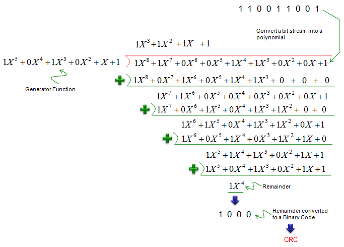
Figure 11. The same division written out over GF(2). Every subtraction step is an XOR, and the remainder that survives becomes the CRC bits.
Here goes a couple of example of Generator Function that is used in various communication system.
The Generator Function that is used in LTE is shown below. (3GPP 36.212 5.1.1 CRC calculation)

Figure 12. The four LTE generator polynomials. CRC24A protects the whole transport block and CRC24B protects each code block inside it.
The Generator Function that is used in UMTS is shown below. (3GPP 25.212 4.2.1.1 CRC Calculation)

Figure 13. Three of the four UMTS polynomials carry straight over to LTE. CRC24 here is bit for bit the same as LTE's CRC24B, and CRC16 and CRC8 are identical as well. CRC12 has no LTE equivalent, and LTE adds CRC24A.
This may be the algorithm that is most commonly used in wireless communication.
How do the four techniques compare ?
The four methods above arrive in order of increasing cost, and that order is not an accident. Each one buys a stronger guarantee than the one before it, and each one pays for that guarantee with more overhead or more computation. Let's set them side by side before looking at what the receiver does with the verdict.
Parity Check |
1 bit per word |
Any odd number of flipped bits. Every even number passes. |
No |
RS-232 serial links, memory parity |
Two Dimensional Parity |
1 bit per row and 1 per column |
Any one, two or three errors. Four errors at the corners of a rectangle pass. |
Yes, one bit per block |
Teaching examples, some tape and memory formats |
Checksum |
16 bits per packet, typically |
Most patterns. Two changes that cancel each other in the sum pass. |
No |
IP, TCP and UDP headers |
CRC |
8 to 24 bits per block |
Every burst shorter than the CRC, and all but about 1 in 2n of everything else. |
No |
Ethernet, WCDMA, LTE, NR |
The two dimensional parity row is the interesting one. It is the only one of the four that corrects anything, and it corrects exactly one bit per block. The row check says which row is wrong, the column check says which column, and the intersection of the two is the address of the bad bit. Flip that bit back and the block is clean again.
Notice also what CRC does not do. It is the most expensive of the four and it is still a detection scheme, so it never corrects a single bit. A mobile system pays 24 bits for a verdict and nothing else, and it takes its correction from a separate mechanism called FEC. That separation is deliberate, and it is the reason the two jobs get two different codes.
Cost buys confidence, not correction : moving down the table raises the chance of catching an error and never adds the ability to fix one. Three of the four schemes here can only report.Only the two dimensional scheme corrects, and only one bit : it works because two independent checks intersect at a single position. Give it two errors in the same row and that intersection stops being unique.Checksum and CRC answer the same question with different strength : both return a yes or a no on the whole block. The CRC is much harder to pass by accident, which is why a radio link uses it and an IP header does not.Match the scheme to the error pattern : choose a CRC when the link produces bursts, because the burst guarantee there is absolute. Choose a locating scheme instead when the errors arrive as scattered single bits.
What is done if the reciever find the error ?
What a system (two communicating parties) do if the reciever find (detect) an error ? We see roughly three different mode of operations depending on what kind of error handling mechanism the system uses as listed below.
- ARQ (Automatic Repeat reQuest)
- FEC (Forward Error Correction)
- HARQ (Hybrid ARQ)
In ARQ, the reciever ask for retransmission of exactly the same data by sending Nack or by skipping any Ack to the transmitter. If the transmitter does get Nack or does not get Ack within a certain time frame, it automatically retransmit the exactly the same data that was transmitted before. The advantage of this mechanism would be that it is simple to implement and it only has to implement error detection algorithm and does not implement the error correction algorithm. The disadvantage would be that the transmiter would have to send the same data so many times if the channel condition is bad and the reciever keep detecting errors. Most common examples for this mechanism would be IP data or RLC layer transmission in WCDMA, LTE.
In FEC, transmitter encode the data before transmitssion in such a way that the reciever not only detect the error but also recover the error unless the amount of the error exceeds a certain level. In this case, the reciever does not request retransmission, in stead it recover (correct) errors from the redundancy bits and specially designed structure contained in the received data itself. The advantage of this mechanis is obvious. It is that we don't need retransmission even when there is error. The disadvantage is that it can recover the error up to only a certain level, if there is more errors exceeding the specific level it is impossible to recover error. In order to enable more capability of error correction, we have to put more redundency bits in the transmitted data, meaning it would increase overhead.
HARQ has the property of both ARQ and FEC. It is a kind of Hybrid algorithm and it is where the name come from. It is Hybrid of ARQ and FEC. When the reciever got a data with error, furst it tries to recover (correct) the error with FEC algorithm. If the error correct was successful, it send Ack to the sender. If it fails, it sends Nack to sender. When the sender got the Nack (or no response) from the reciever, it retransmit the data but when it retransmit the data, it usually send a little bit different sets of the original data (we call it 'different redundency version') and the reciever combines the previous copy and the retransmitted copy to increase probability of error recovery. The advantage of this algorithm is that it adopts the advantage of both ARQ and FEC and reducing the disadvantage of FEC and ARQ. But this would be more complicated to implement than simple ARQ and FEC. One common example of this mechanism is Physical layer communication in HSDPA and LTE. For further details, refer to LTE HARQ page.
What do LTE and NR actually use ?
Everything so far has been generic, so let's finish on the concrete case. A 3GPP system uses several of these ideas at once, and it deliberately keeps the detection job and the correction job in separate codes. Knowing which code does which makes a log much easier to read, because a CRC failure and a decoding failure do not mean the same thing.
Detection is CRC, and every transport block carries two levels of it. The transmitter attaches CRC24A to the whole transport block first. It then splits that block into code blocks when the block is too long for the encoder, and attaches CRC24B to each code block. LTE defines both polynomials in 36.212 section 5.1.1, and NR keeps the same two in 38.212 while adding CRC24C, CRC11 and CRC6 for the control channels.
Figure 14 draws that two level structure. The row to look at is the middle one, where every code block carries a check of its own.
Figure 14. The two CRC levels on one transport block. CRC24A covers everything and decides Ack or Nack, while CRC24B gives each code block a verdict the receiver can act on separately.
Correction is a different code, and this is where LTE and NR differ. LTE encodes the data channels with a Turbo code and the control channels with a tail biting convolutional code. NR replaces both of them: LDPC for the data channels, and Polar for the larger control messages. The CRC polynomials barely changed across that switch, because the CRC was never the part doing the correcting.
HARQ is the layer above both of them. The receiver decodes, checks the CRC, and sends an Ack or a Nack on the strength of that check alone. A Nack triggers a retransmission that carries a different redundancy version, and the receiver combines that copy with the one it already holds. The whole retransmission loop therefore runs on one yes-or-no test.
CRC24A is the verdict on the transport block : it is the check the MAC layer acts on, and it is the check that decides Ack or Nack on the uplink control channel.CRC24B makes each code block answerable on its own : the receiver learns which code block failed rather than only that something failed, and NR code block group retransmission is built on exactly that.Detection and correction use different codes on purpose : a Turbo or LDPC decoder produces its best guess and cannot tell you whether that guess is right. The CRC is the independent check that answers the question.A CRC failure and a decode failure are not the same log entry : a failing CRC says the block did not survive. It does not say the decoder gave up, and on a HARQ retransmission the two look very different.