MAC hands the physical layer one transport block and expects it to arrive intact at the other end. The radio will corrupt some of it, so the physical layer adds redundancy before transmitting and uses that redundancy to repair what arrives. Channel coding is where that redundancy is added, and 36.212 sets out the five steps in a fixed order.
Two numbers are worth remembering while you read. The transport block arrives as A bits, and it leaves this chain as G bits. Everything in between either fixes the length by rule or, in one single step, chooses it to fit the air interface allocation.
- Channel Coding Processing for DL SCH/PCH/MCH
- How many bits at each stage ?
- PDSCH Encoding in srsRAN
- Reference
Channel Coding Processing for DL SCH/PCH/MCH
First as a disclaimer, I am very early stage of studying this field. For a long time since I joined into the wireless communication, this kind of processing has always the part that I was so eager to undersand but eventually gave up. In LTE as well, the document like 36.211, 36.212 were mysterious specification to me. I have always wondering "How those guys can implement real device(PHY) just by reading these thin, vague, cloudy (at leas to me) documents ?".
Very recently an expert in this area helped me so much to get some insight/big picture to start with. (I still think several month to go to be able to draw detailed picture for this, but getting the initial big picture would be the most important step).
Here goes my first picture and this will get more detailed illustration later... so keep checking this part if you are interested.
The first picture you have to be familiar (don't try to memorize... just see this as often as possible and just make it familiar) . This figure is from 36.212.
Let's just make a two important bulets here. Whatever a processing unit is, the first and most important steps you have to understand is "What is the input ?" and "What is the output ?".
What is the input of this whole process ? It is a transport block.
What is the output of this whole process ? It is a series of IQ data to be transmitted from PHY.
So the whole purpose of this process is "to convert a transport block (from MAC) into a series of bit stream data to be transmitted".
< 36.212 - Figure 5.3.2-1: Transport block processing for DL-SCH, PCH and MCH.>

36.212 Figure 5.3.2-1. The whole chain in one picture. The bit vector names beside each arrow are the page’s map, because every step below is one of these boxes.
- Five boxes run down the page, and the sections below take them in the same order. They are Transport block CRC attachment, Code block segmentation and Code block CRC attachment, Channel coding, Rate matching, then Code block concatenation.
- The letters change at every arrow, from a to b to c to d to e to f. That is the quickest way to tell which step a formula in 36.212 belongs to.
- Only the d vector carries a superscript, written d(i). That superscript is the reason the diagram needs a rate matching step at all.
Now let's look into each step of the process.
The first step is pretty simple. Just adding 24 bits of CRC block to the end of the input (transport block).

Figure 1. Transport block CRC attachment. The note at the foot states the whole step in one line, B = A + 24.
- The callout at the top right names the input for what it is, a Transport Block from MAC. Nothing has been added to it yet.
- The darker cells at the end of the lower row are the CRC, bracketed and labelled CRC = 24 bits. The original a bits are unchanged and sit in front of them.
- 36.212 calls this CRC gCRC24A, which is a different polynomial from the one the next step uses.
The second step is as follows. It is splitting the big transport block into multiple small blocks and add another CRC to each of the split chunks. Sounds simple ? but there is a couple of things to make it tricky. Why do we need to split the block ? Do we always to have to split the input block ? It would be understandable to split a very large input block into multiple smaller block, but if we have to split even a small input block, isn't it inefficient ?
The generic answer is that the process split the input block only when the block is very large.
Then the question is "How large it would be to be splitted ?" In LTE case, 6144 (bits) is the number. (See 5.1.2 Code block segmentation and code block CRC attachment of 36.212)

Figure 2. Code block segmentation. One row becomes r rows, and each row is given a CRC of its own.
- The rows are numbered 1, 2 down to r, and the bits are renamed to cr0 onward. The r subscript is the code block number.
- Each row ends in its own bracketed CRC = 24 bits. 36.212 uses gCRC24B here, and it attaches one only when there is more than one code block.
- The split happens only when B is larger than 6144, which is the number the prose above quotes. A smaller transport block stays as a single code block.
Next step is the famous Turbo Coding step. I am not able to explain on how turbo coding works in easy/plain language mainly because I don't understand it clearly. But for now, let's just focus on only one fact. If you see the turbo coding block diagram in 36.212. You would see that one bit input become 3 bit output as it goes through the turbo coding processor (It means the coding rate is 1/3). In this process, one input row generate three rows of output as follows.
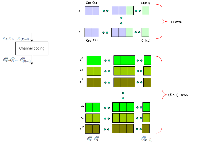
Figure 3. Channel coding. The brackets say it plainly: r rows go in and 3 x r rows come out, which is the rate 1/3 the prose describes.
- The lower block groups its rows in threes, labelled 10, 11, 12 down to r0, r1, r2. Each group of three belongs to one code block.
- The three shades inside a group are the three output streams of the turbo coder, and they are what the superscript in d(i) counts.
- Nothing here chooses a length. The coder produces three streams whatever the allocation looks like, and the next step deals with that.
Next step is Rate Matching step. This is the most mesterious part to me. The generic Idea is like this. I said Turbo coding generate three rows of output for each row of input. In this rate matching process, the each set of three rows of input stream became one row of bit stream. The question is "How to convert the a set of three row into one row ?" Is it just by concatenating the three row into one long row ? Is it just random mix of the three row ? Is it by interleaving the three row into one ?".
This is the question you have to find the answer from 5.1.4.1 Rate matching for turbo coded transport channels of 36.212. Good luck with your endeaver -:) I think it will take a couple of month for me to understand this even with a good tutor around me.

Figure 4. Rate matching. The 3 x r rows collapse back to r rows, and the length of each row is the one number the network actually chooses.
- The brackets are the whole story. (3 x r) rows on top, r rows underneath, so each group of three becomes one.
- The output row is written er0 to er(Er-1). Er is set by how much room the scheduler gave this transmission, not by the coder.
- This is also where the redundancy version acts. A retransmission runs the same d bits through this step again and takes a different part of them.
Just adding another big picture to this rate matching step, take a quick look at the following figure from 36.212. You see the three lines of Turbo coding output gets into this rate matching block and comes out as a single line of bit stream. Our goal is to understanding the detailed process of "interleaving", "BitCollection", "Bit Selection and pruning" procedure.
< 36.212 - Figure 5.1.4-1. Rate matching for turbo coded transport channels >

36.212 Figure 5.1.4-1. What rate matching does inside. The virtual circular buffer is where the three streams become one, and Bit selection and pruning is what sets the output length.
- Three inputs enter on the left, dk(0), dk(1) and dk(2). They are the three streams Figure 3 produced.
- Each passes its own Sub-block interleaver before anything is combined. So the answer to the question the prose asks is interleaving first, then collection.
- Bit collection writes the interleaved streams into the buffer marked virtual circular buffer. Bit selection and pruning then reads out as many bits as the allocation needs, which is why the buffer is circular.
Next is the last step which is relatively simple. Combine the multiple rows of imput into one long bit stream as shown below.

Figure 5. Code block concatenation. The r rows become one stream, f0 to fG-1, and that is the end of the 36.212 chain.
- The step does what its name says and nothing more. The rows are laid end to end in order, and no bits are added or dropped.
- G is therefore the sum of the Er values from Figure 4, so the allocation decided this number several steps earlier.
- The colour changes at this step in the drawing, which marks the handover from the coding chain to the physical channel processing that follows.
Now you may have a question. Is this the end of the process ? Are these data get directly transmitted out of the antenna ? Unfortunately No. The output of this complicated process become the input (starting point) of another complicated process as shown below. I means there are a lot of stuffs you have to study pulling the hair -:)
< 36.211 - Figure 6.3-1: Overview of physical channel processing >

36.211 Figure 6.3-1. Where the bits go next. Everything on this page produces the code words at the far left, and IQ samples only appear after OFDM signal generation at the far right.
- Two parallel chains leave code words on the left, which is why the diagram can carry two transport blocks at once.
- Scrambling and Modulation mapper still work on bits and symbols per code word. Layer mapper and Precoding are the first blocks that mix the chains together.
- 36.211 Figure 6.3-1 sits in a different specification from everything above it. Crossing that boundary is what the paragraph above means by another complicated process.
The chain never chooses a length until rate matching : CRC, segmentation and coding all follow fixed rules, so rate matching is the only step the scheduler influences.Two different CRCs appear, not one : gCRC24A goes on the transport block and gCRC24B goes on each code block, and the second only appears when the block was split.The output is bits, not symbols : this chain ends at f0 to fG-1, and 36.211 Figure 6.3-1 is where those bits become something transmittable.
How many bits at each stage ?
The drawings above each show one step, and the bracket labels carry the arithmetic. Putting them side by side answers a question the individual pictures cannot: where in this chain does the length actually get decided? The answer is one step, and it is not the coder.
Stage |
Bits are called |
What happens to the length |
Input from MAC |
a0 … aA-1 |
A bits. This is the transport block, and its size was fixed when the grant was built. |
Transport block CRC attachment |
b0 … bB-1 |
B = A + 24, always. The polynomial is gCRC24A. |
Code block segmentation |
cr0 … cr(Kr-1) |
Nothing happens unless B is larger than Z = 6144. When it is, the block is split and each piece gets a 24 bit gCRC24B. |
Channel coding |
dr0(i) … |
Three streams come out for every code block that went in, so the count roughly triples. |
Rate matching |
er0 … er(Er-1) |
Three streams become one, and Er is chosen to fit the allocation. This is the only step the scheduler influences. |
Code block concatenation |
f0 … fG-1 |
The rows are joined end to end, so G is simply the sum of the Er values. |
Two rows in that table are conditional, and they are the ones that cause confusion in a log. Segmentation does nothing at all when the transport block is small. A single code block carries no second CRC, so those 24 bits are simply not there to count.
36.212 adds one more condition at the same step. When the split does not divide evenly it inserts filler bits at the front of the first code block, and it also pads any block shorter than 40 bits. Those filler bits are set to a null value at the encoder input, so they occupy positions without carrying data.
Reading the table downward also shows why a retransmission costs nothing above the physical layer. The a, b, c and d vectors are identical every time, because none of those steps depends on the allocation. Only the e vector changes, and it changes because bit selection starts at a different point in the circular buffer.
Only rate matching depends on the allocation : every other row follows a rule the scheduler cannot change.The second CRC is conditional : a transport block small enough for one code block never gets a gCRC24B. So B and the sum of the Kr values are not always 24 bits apart.G was decided before the coder ran : the allocation sets the output length, and the chain works backward from it rather than forward from A.
PDSCH Encoding in srsRAN
If you are interested in this process at the source code level of the protocol stack, I would suggest you to look into the openSource srsRAN. Following APIs can be good places for you to start. This list is from the master-branch of the code that was downloaded on Oct 8,2021
- srsran_rm_turbo_tx_lut() -> \lib\src\phy\fec\turbo\rm_turbo.c
- srsran_tcod_encode_lut() -> \lib\src\phy\fec\turbo\turbocoder.c
- srsran_crc_set_init() -> \lib\src\phy\fec\crc.c
- encode_tb_off() -> \lib\src\phy\phch\sch.c
- encode_tb() -> \lib\src\phy\phch\sch.c
- srsran_dlsch_encode2() -> \lib\src\phy\phch\sch.c
- srsran_sequence_apply_packed() -> \lib\src\phy\phch\sequence.c
- srsran_sequence_pdsch_apply_pack() -> \lib\src\phy\phch\sequences.c
- srsran_layermap_single() -> \lib\src\phy\mimo\layermap.c
- srsran_layermap_diversity() -> \lib\src\phy\mimo\layermap.c
- srsran_layermap_multiplex() -> \lib\src\phy\mimo\layermap.c
- srsran_layermap_type() -> \lib\src\phy\mimo\layermap.c
- srsran_predecoding_single_csi() -> \lib\src\phy\mimo\precoding.c
- srsran_precoding_single() -> \lib\src\phy\mimo\precoding.c
- srsran_predecoding_diversity_csi() -> \lib\src\phy\mimo\precoding.c
- srsran_predecoding_diversity_multi() -> \lib\src\phy\mimo\precoding.c
- srsran_predecoding_diversity2_sse() -> \lib\src\phy\mimo\precoding.c
- srsran_predecoding_diversity_gen() -> \lib\src\phy\mimo\precoding.c
- srsran_precoding_cdd_2x2_gen() -> \lib\src\phy\mimo\precoding.c
- srsran_precoding_cdd_2x2_sse() -> \lib\src\phy\mimo\precoding.c
- srsran_precoding_cdd_2x2_avx() -> \lib\src\phy\mimo\precoding.c
- srsran_precoding_cdd() -> \lib\src\phy\mimo\precoding.c
- srsran_precoding_type() -> \lib\src\phy\mimo\precoding.c
- srsran_pdsch_cp() -> \lib\src\phy\phch\pdsch.c
- srsran_pdsch_put() -> \lib\src\phy\phch\pdsch.c
- srsran_precoding_2x2_cn_gen() -> \lib\src\phy\mimo\precoding.c
- srsran_precoding_cn() -> \lib\src\phy\mimo\precoding.c
- srsran_precoding_pmi_select_2l() -> \lib\src\phy\mimo\precoding.c
- srsran_precoding_pmi_select_1l() -> \lib\src\phy\mimo\precoding.c
- srsran_precoding_pmi_select() -> \lib\src\phy\mimo\precoding.c
- srsran_pdsch_select_pmi() -> \lib\src\phy\phch\pdsch.c
- srsran_mod_modulate_bytes() -> \lib\src\phy\modem\mod.c
srsran_pdsch_codeword_encode() -> \lib\src\phy\phch\pdsch.c
Read as a flat list those names are hard to place. The two figures on this page give them an order. The grouping below comes from the function names and their directory paths rather than from reading the code.
Stage |
Specified in |
srsRAN names |
Transport block and code block CRC |
36.212 |
srsran_crc_set_init() |
Channel coding |
36.212 |
srsran_tcod_encode_lut() |
Rate matching |
36.212 |
srsran_rm_turbo_tx_lut() |
The chain as a whole |
36.212 |
encode_tb(), encode_tb_off(), srsran_dlsch_encode2() |
Scrambling |
36.211 |
srsran_sequence_apply_packed(), srsran_sequence_pdsch_apply_pack() |
Modulation mapper |
36.211 |
srsran_mod_modulate_bytes() |
Layer mapper |
36.211 |
the srsran_layermap_ family |
Precoding |
36.211 |
the srsran_precoding_ and srsran_predecoding_ families |
Resource element mapper |
36.211 |
srsran_pdsch_put(), srsran_pdsch_cp() |
Top of the whole encode path |
both |
srsran_pdsch_codeword_encode() |
The split in the middle column is the useful part. Four entries belong to the chain this page describes, and the rest belong to 36.211 Figure 6.3-1. So the list quietly crosses the boundary that the last paragraph of the previous section warns about.
The marked entry is the one to open first, because srsran_pdsch_codeword_encode() sits at the top of the path and the others are reached from it. Starting anywhere else means reading upward to find out who called it.
The list spans two specifications : the fec and sch files implement 36.212, while the mimo and modem files implement 36.211 Figure 6.3-1.Directory names follow the specification : phy/fec holds coding, phy/mimo holds layer mapping and precoding, and phy/phch holds the per-channel assembly.Start at the top and read down : srsran_pdsch_codeword_encode() calls into the rest, so it gives the order the other names appear in.
Reference
- TS 36.212 v19.3.0 (Release 19) - E-UTRA Multiplexing and channel coding. Clauses 5.1.1 to 5.1.5 and 5.3.2.