RRC stands for Radio Resource Control. I personally define RRC as a common language that should be understood by both Network and UE. As you know, UE and Network is communicating via radio channel. Every parties participating in the communication should exchange a lot of information to make the real data exchange possible. In other words, the final goal of communication is to exchange the data (user data) between communicating parties, but to make this happen there are a lot of things (especially a lot of lower layer issues) that need to be configured in common. In case of low end communication system, those common configuration is done before the product is released into market and once they are released, those configuration would not change. However, in many high end communication system (e.g, cellular communication) these configuration should change dynamically for optimal configuration at the time of communication. Then the question is how both parties in the communication reach agreement on those common configuration. To do this, we need a special control mechanism to exchange informations on those configurations between communicating parties. The resulting implementation of this control mechanism is called RRC (Radio Resource Control).
Another central role of RRC within each communicating party (i.e, within UE and Network) is to work as a control center for all of the lower layers within each system. The collection of all the lower layers within UE or basestation is called 'Radio Resource' (i.e, resources required to make radio communication possible). The major role of RRC is to control(configure) all the Radio Resources (PHY, MAC, RLC, PDCP) to make it possible to communicate between UE and the base station (e.g, gNB, eNB, NB, BTS etc).
In this page, I will give you the brief introduction to RRC in NR. In fact, RRC is a huge topic because it eventually get involved in whole protocol stack. So it would be difficult to describe the wholes details of RRC in single page. So I would just talk about overall RRC structure / functions in this page and for further details I will write many separate pages and put the links in this page.
- RRC State in NR
- Comparison of the Three RRC States
- NR RRC CONNECTED <-> INACTIVE State Change
- NR RRC Interaction with LTE RRC
- NR RRC Interaction with UTRAN / GERAN RRC
- RRC Functions and Signalling Radio Bearers
- Reference
RRC State in NR
When you think of RRC in NR only, it can be illustrated as shown below. Do you see any difference from LTE RRC ? Yes, you might have noticed that a new block (state) are introduced in NR. It is 'NR RRC INACTIVE'. Full details of this new state is not fully defined in the specification yet, but my first impression of the function and purpose of this new state would be similar to the combined functionality of CELL PACH and CELL/URA PCH in UMTS RRC State Change process.
< TR 38.804- Figure 5.5.2-1 : UE state machine and state transitions in NR >
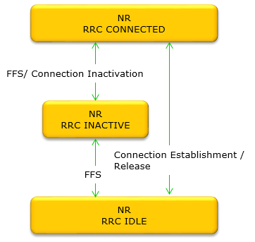
Look closely at the arrows in TR 38.804 Figure 5.5.2-1 and you will find the word
One more thing is worth reading off the figure before we move on. There are only three boxes, and 38.331 is explicit that a UE has exactly one RRC state in NR at any time. A UE is therefore never partly connected and partly inactive, however similar the two look from the radio side.
Comparison of the Three RRC States
TR 38.804 Figure 5.5.2-1 tells you that three states exist. It does not tell you what living in each of them is actually like, and that is the part that matters when you are reading a log. So let's take the three apart and put them side by side.
Start with the sentence that explains why RRC_INACTIVE was invented at all. 38.300 puts it plainly. A UE in RRC_INACTIVE remains in
That single fact is the whole point of the state. Going from IDLE to CONNECTED means building an RRC connection and a core network connection from nothing. Going from INACTIVE to CONNECTED means waking a link whose context both ends already hold. The second is far cheaper, and that is what makes it useful for traffic arriving in short bursts.
Property |
RRC_IDLE |
RRC_INACTIVE |
RRC_CONNECTED |
None |
Established, then suspended |
Established and active |
|
CM-IDLE |
CM-CONNECTED |
||
Not held in the RAN |
The UE stores the Inactive AS context, and the last serving gNB keeps its copy |
The UE and the serving gNB both hold the AS context |
|
The UE, by cell reselection on network configuration |
The UE, by cell reselection on network configuration |
||
Tracking Area, held by the AMF |
The serving cell itself |
||
CN paging, on 5G-S-TMSI |
CN paging on 5G-S-TMSI, and RAN paging on fullI-RNTI |
Not paged. It monitors its own control channels |
|
No |
Only over bearers configured for SDT |
Yes |
Two rows in that table deserve a second look, because they are where the states are most often confused.
The mobility row separates CONNECTED from the other two. In IDLE and INACTIVE the UE decides where to go, using reselection parameters the network broadcast to everyone. In CONNECTED the network decides, using measurement reports the UE sends it. That is why a CONNECTED UE needs a measurement configuration and an IDLE UE does not.
The notification area row separates INACTIVE from IDLE. An IDLE UE tells the AMF when it leaves its Tracking Area. An INACTIVE UE tells the gNB when it leaves its RAN-based Notification Area, and 38.300 requires that area to sit inside the CN registration area. So an INACTIVE UE can move around a small area with no signalling at all, and the network still knows where to page it.
RRC_INACTIVE keeps the core network connection : the UE stays CM-CONNECTED and the last serving gNB holds the context, so resuming costs far less than establishing.Mobility control is the CONNECTED dividing line : the UE reselects in IDLE and INACTIVE, and the network hands over in CONNECTED.The notification area is the INACTIVE dividing line : a Tracking Area update goes to the AMF, and an RNA update goes to the gNB still holding your context.A UE holds exactly one RRC state : 38.331 says so directly, so the three boxes are alternatives and they never overlap.
NR RRC CONNECTED <-> INACTIVE State Change
Unlike LTE, in NR there is a addition RRC states between RRC Connected and Idle and Network/UE can optionally stay in INACTIVE state without completely releasing the RRC when there is no traffic and quickly switch back to CONNECTED states when necessary. To me, RRC INACTIVE state is similar to the combination of FACH and PCH in UMTS. Actually Use case of INACTIVE state is almost same as FACH/PCH in UMTS.
The switching between RRC CONNECTED and RRC INACTIVE state happens as shown below.

The details of this transition is described in a separate note : RRC INACTIVE
Each arrow carries the name of the message that causes it, and those are the names you will meet in a log.
CONNECTED to INACTIVE : the network sendsRRCRelease with asuspendConfig in it. The name misleads the first time you see it, because the connection is suspended rather than released. The suspendConfig is what carries the I-RNTI and the RAN notification area configuration.INACTIVE to CONNECTED : the UE sendsRRCResumeRequest , orRRCResumeRequest1 when the full I-RNTI is used instead of the short one. The network can also start the move, by paging the UE.INACTIVE to IDLE : a plainRRCRelease with no suspendConfig. The stored context is dropped, and the next move back to CONNECTED needs a full establishment.
Notice that the same message name appears twice, once with suspendConfig and once without. That one optional field decides whether the UE lands in INACTIVE or in IDLE. It is the first thing to check when a device keeps ending up in the wrong state.
NR RRC Interaction with LTE RRC
NR RRC does not only involved in NR but also in other radio access technology as well. The interaction of NR RRC and LTE RRC can be illustrated as follows. Things to be noticed here are
- NR can reselect to LTE (E-UTRA) and LTE can reselect to NR while they are in IDLE state
- But when NR is in RRC INACTIVE state, NR RRC INACTIVE can reslect to EUTRA and EUTRA can reselect to NR.
< 36.331 v16.5-Figure 4.2.1-6: Mobility procedures between E-UTRA/EPC, E-UTRA/5GC and NR >
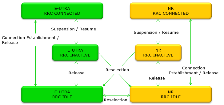
36.331 Figure 4.2.1-6 is drawn as two columns, E-UTRA on the left and NR on the right, and each column carries the same three states. Reading one column at a time first makes the cross links much easier to follow afterwards.
Within a column the picture is the ordinary one. Connection Establishment / Release moves the UE between IDLE and CONNECTED. Suspension / Resume moves it between CONNECTED and INACTIVE, and Release drops it from INACTIVE to IDLE. E-UTRA gained an INACTIVE state of its own once it could connect to a 5GC. That is why the left column looks like the right one rather than like classic LTE.
The cross links are the interesting part, and every one of them ends on an IDLE box. Reselection runs both ways between E-UTRA RRC IDLE and NR RRC IDLE. Reselection also runs out of both INACTIVE states towards the other technology. What you will not find anywhere on the figure is an arrow arriving at the other side's INACTIVE box, and that is the rule worth remembering. You can leave INACTIVE across technologies, but you cannot arrive in it.
That asymmetry follows from what INACTIVE is. The state exists because one gNB is still holding your context, and a node in another radio access technology is holding nothing for you.
NR RRC Interaction with UTRAN / GERAN RRC
The last of the inter-RAT pictures reaches further back, to UMTS and GSM. It matters a little less every year, but it is still the fastest way to see how much the NR state machine borrowed from UTRAN, and where the borrowing stopped.
The interaction of NR RRC and UMTS / GSM RRC can be illustrated as follows. Things to be noticed here are
- NR can reselect to UMTS (UTRA) and UMTS can reselect to NR while they are in IDLE state
- But when NR is in RRC INACTIVE state, NR RRC INACTIVE can reslect to UTRA (UTRA IDLE), but UTRA (UTRA IDLE) cannot reselect to NR RRC INACTIVE state
- UMTS CELL FACH and CELL/URA PCH can reselect to NR IDLE, but NR IDLE cannot reselect to UMTS CELL FACH or CELL/URA PCH.
- NR can reselect to GSM (GERAN) while they are in IDLE state
- GSM can do CCO (Cell Change Order) to NR while they are in IDLE state
- GPRS can reselect to NR IDLE even while it is in GPRS Packet Transfer Mode
- GPRS can do CCO to NR IDLE while it is in GPRS Packet Transfer Mode
< TR 38.804 - Figure 10.2-3:UE state machine and state transitions between NR and UTRAN/GERAN>
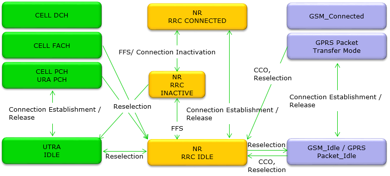
TR 38.804 Figure 10.2-3 sets three state machines beside each other. UTRAN is on the left, with CELL DCH, CELL FACH and CELL PCH / URA PCH above UTRA IDLE. NR is in the middle. GSM and GPRS are on the right, with GSM_Connected, GPRS Packet Transfer Mode and a combined GSM_Idle / GPRS Packet_Idle box.
Put the left column next to the middle one and the family resemblance is obvious. UTRAN already had states between fully connected and fully idle, and it had several of them. CELL PCH and URA PCH keep the UE known to the network while it uses very little power. URA PCH even has its own registration area, updated only when the UE leaves it. That is the same job the RAN-based Notification Area does for RRC_INACTIVE.
So the comparison the opening of this page makes is a fair one, and it has grown more accurate rather than less. Release 17 added Small Data Transmission, which lets an INACTIVE UE send and receive a little data without returning to CONNECTED. That brings RRC_INACTIVE closer to CELL FACH than it was when this page was first written.
The GSM side has no equivalent at all, which is why the right hand column only ever connects to NR RRC IDLE. Notice the two arrows labelled CCO as well. Cell Change Order is a GERAN mechanism, and TR 38.804 Figure 10.2-3 shows it running one way only. GSM and GPRS can order a move to NR, and NR does not order a move back.
URA PCH is the ancestor of RRC_INACTIVE : it kept the UE known to the RAN inside a registration area, updated only on leaving. That is what the RNA does now.Small Data Transmission narrowed the gap with CELL FACH : an INACTIVE UE can now move a little data without a full transition to CONNECTED.Everything from GSM lands in NR RRC IDLE : there is no GERAN state that maps onto INACTIVE, so no arrow reaches it.CCO is one directional here : GERAN can order a change to NR, and the figure shows nothing going the other way.
RRC Functions and Signalling Radio Bearers
The opening of this page promised a look at what RRC does, and so far we have only looked at which state it is in. Let's close that gap. 38.331 groups the whole protocol into a handful of functions, and they are far easier to remember as groups than as a flat list.
Function group |
What it covers |
Everything a UE needs before it has a connection. Cell reselection and neighbour information for IDLE and INACTIVE, common channel configuration for CONNECTED, ETWS and CMAS warning notifications, and positioning assistance data. |
|
Paging, and the establishment, modification, suspension, resumption and release of the connection. Also access barring, the initial AS security activation, handover, the setup of SRBs and DRBs, and the radio configuration itself including DRX, HARQ and ARQ. |
|
Setting up intra-frequency, inter-frequency and inter-RAT measurements, opening and closing measurement gaps, and carrying the reports back to the network. |
|
Detecting that the link has gone, and re-establishing rather than starting again from nothing. |
|
Moving to and from E-UTRA and to UTRA-FDD, with the AS security activation and the RRC context transfer that go with it. This is the function behind the two sections above. |
|
Carrying dedicated NAS information between the UE and the core, and reporting the UE radio access capability. RRC is the courier here rather than the reader. |
Read that table against the state sections above and a pattern appears. Nearly everything in the connection control row applies only in RRC_CONNECTED. The broadcast row is the only one that reaches a UE with no connection at all. That is why system information has to carry everything an IDLE UE needs in order to choose a cell on its own.
Signalling Radio Bearers
RRC messages do not travel on their own. They travel on Signalling Radio Bearers, and which SRB a message uses tells you a great deal about when in a call that message can appear.
SRB |
Logical channel |
What it carries, and when |
CCCH |
RRC messages only, before there is a connection worth the name. It exists from the start, and it can carry no protection because no key has been agreed yet. |
|
DCCH |
RRC messages, which may carry a piggybacked NAS message, and NAS messages themselves until SRB2 exists. |
|
DCCH |
NAS messages, and RRC messages carrying logged measurement information. Lower priority than SRB1, and the network may configure it only after AS security is activated. |
|
DCCH |
Specific RRC messages exchanged directly with the secondary node. It exists only in (NG)EN-DC or NR-DC. |
|
DCCH |
RRC messages carrying application layer measurement reports. Lower priority than SRB1, and configurable only after AS security is activated. |
|
DCCH |
Application layer measurement reports again, but configured by the node serving the SCG. It exists only in NR-DC, after AS security is activated. |
|
DCCH |
Logged measurement information for network side data collection. Lower priority than SRB1, and configurable only after AS security is activated. |
SRB0 is the one to remember. It runs on CCCH, it carries the messages a UE sends before it holds any security context, and it therefore cannot be ciphered or integrity protected. Everything from SRB1 upward is protected by PDCP once AS security has been activated.
Notice how many of these are recent. SRB4, SRB5 and SRB6 all exist to carry measurement or logging information that earlier releases had nowhere to put. A description written a few years ago will stop at SRB3, and it is not wrong so much as out of date.
System information is the only function that reaches an unconnected UE : everything an IDLE UE needs in order to pick a cell has to be broadcast. There is no dedicated signalling to send it on.Connection control is most of the protocol : paging, setup, suspend, resume, release, security, handover and the radio configuration all sit inside one function group.SRB0 cannot be protected : it runs on CCCH before any key exists, so the messages it carries are the ones an attacker can read.The SRB list keeps growing : SRB4, SRB5 and SRB6 were added for application layer and logged measurement reporting, so a list stopping at SRB3 is simply an older one.
Reference
- [1] 38.331 v19.3.0 : NR - Radio Resource Control (RRC) protocol specification. Clauses 4.2.1, 4.2.2, 4.3 and 4.4 were read for this page.
- [2] 38.300 v19.3.0 : NR and NG-RAN Overall Description. Clause 9.2.2 and the RRC_INACTIVE description in clause 9.2 were read.
- [3] TR 38.804 : Study on New Radio Access Technology, Radio Interface Protocol Aspects. The source of the two state machine figures already on this page. Not opened for this pass.
- [4] 36.331 : E-UTRA Radio Resource Control (RRC) protocol specification. The source of Figure 4.2.1-6 already on this page. Not opened for this pass.
Coverage is partial. 38.331 and 38.300 are both long, and I read the clauses listed above rather than the whole of either one.