Matlab Toolbox - 4G/LTE
EPDCCH
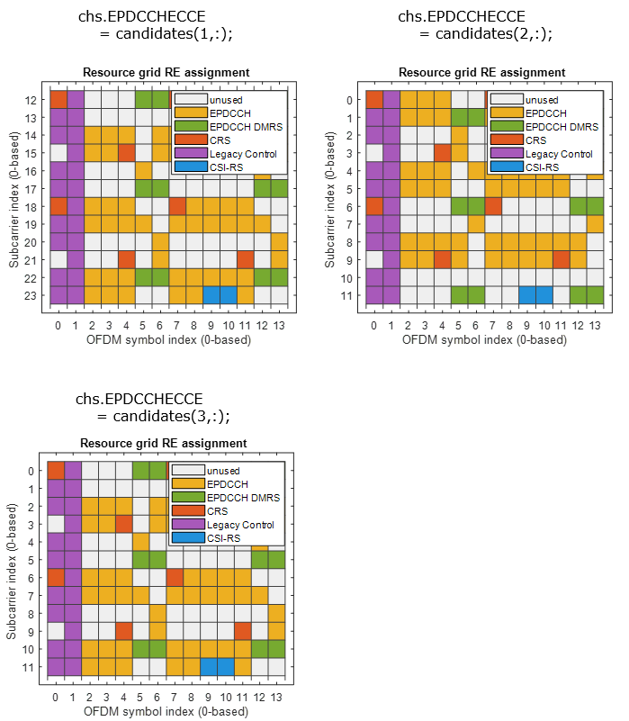
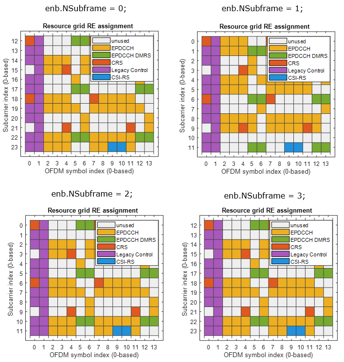
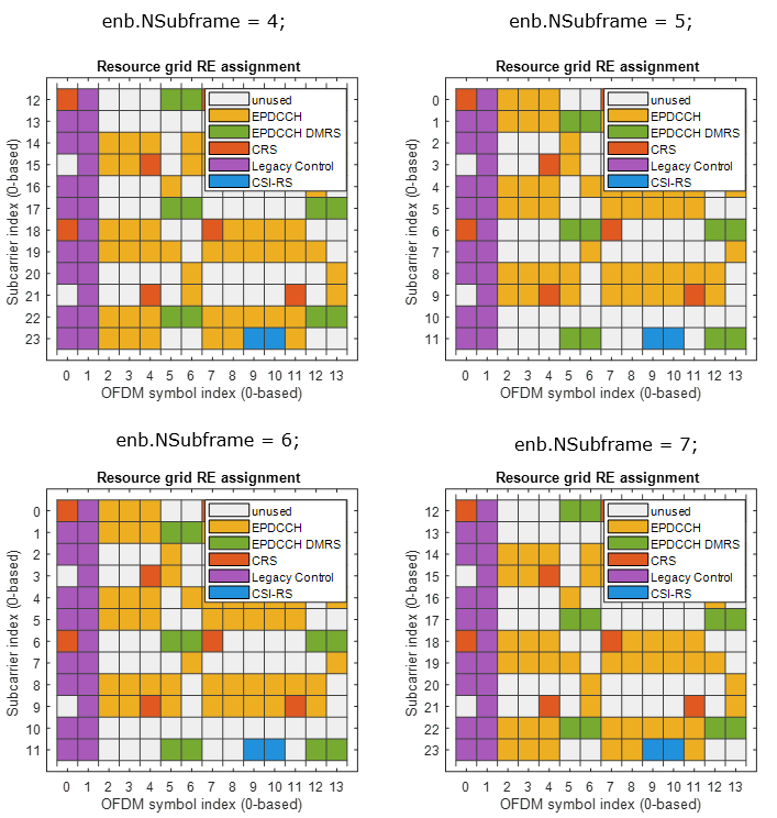
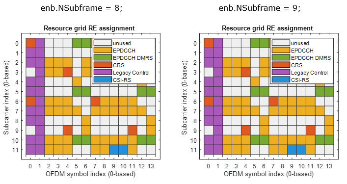
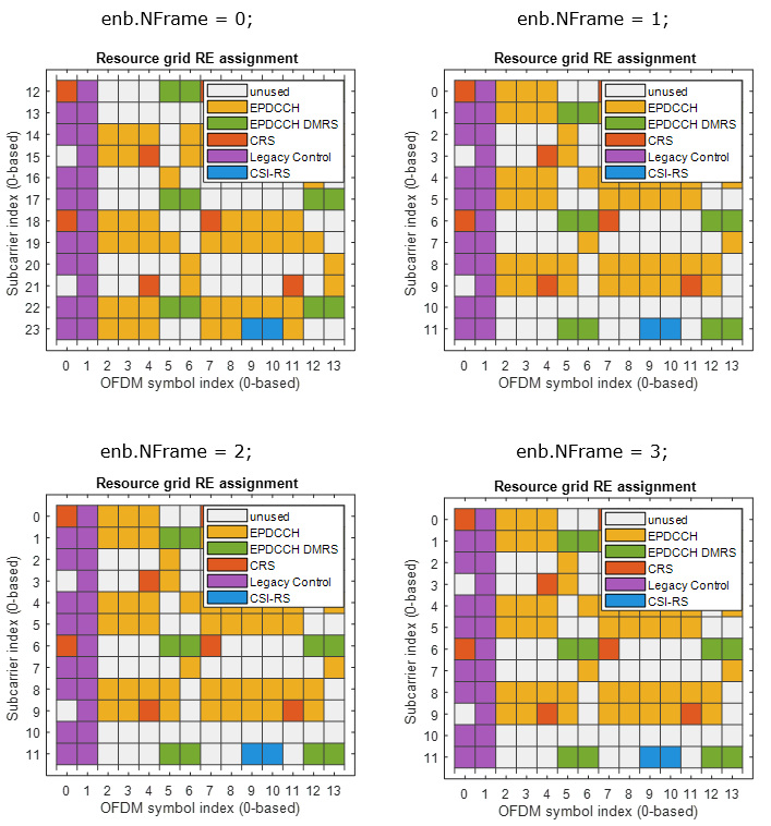
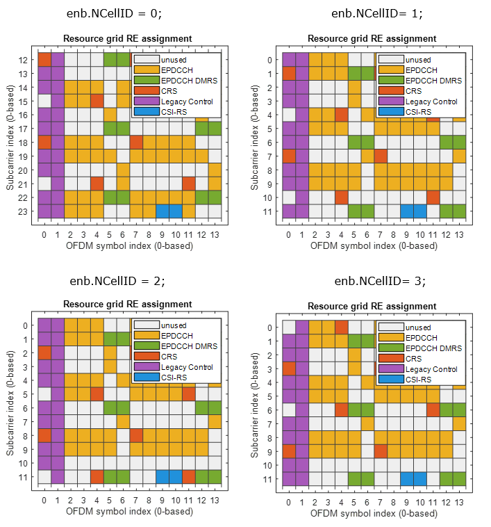
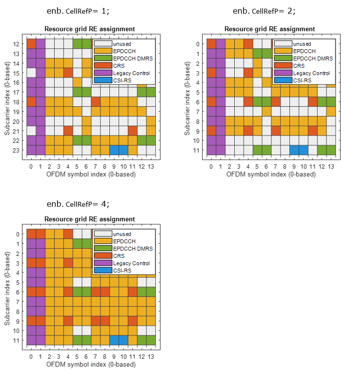
The main purpose of this page is to show the examples of EPDCCH RE mapping with various parameter change to give you intuitive understandings on how the control data is allocated to resource elements. The code in this page is based on Matlab official example page Enhanced Physical Downlink Control Channel (EPDCCH) Generation, but I simplified a lot only for EPDCCH RE mapping.
< EPDCCH RE Mapping>
enb.NDLRB = 25;
enb.DuplexMode = 'FDD';
enb.CellRefP = 1;
enb.NSubframe = 0;
enb.CyclicPrefix = 'Normal';
enb.NFrame = 0;
enb.NCellID = 0;
enb.CSIRSPeriod = 'On';
enb.CSIRSConfig = 1;
enb.CSIRefP = 1;
enb.ZeroPowerCSIRSPeriod = 'Off';
chs.DCIFormat = 'Format1A';
chs.RNTI = 1;
chs.EPDCCHType = 'Localized';
chs.EPDCCHPRBSet = 0:1;
chs.EPDCCHStart = 2;
chs.EPDCCHNID = 0;
chs.EPDCCHFormat = 1;
maxEpdcchPorts = 0;
nTxAnts = max([enb.CSIRefP enb.CellRefP maxEpdcchPorts]);
subframe = lteDLResourceGrid(enb,nTxAnts);
candidates = lteEPDCCHSpace(enb,chs);
chs.EPDCCHECCE = candidates(3,:);
hEPDCCHGenerationPlot(enb,chs);
|
enb.CellRefP = 1; enb.NSubframe = 0; enb.NFrame = 0; enb.NCellID = 0; enb.CSIRSPeriod = 'On'; enb.CSIRSConfig = 1; enb.CSIRefP = 1; enb.ZeroPowerCSIRSPeriod = 'Off';
chs.EPDCCHPRBSet = 0:1; chs.EPDCCHStart = 2; chs.EPDCCHNID = 0; chs.EPDCCHFormat = 1;
chs.EPDCCHECCE = candidates(3,:); |
|
|
|
enb.CellRefP = 1; enb.NSubframe = 0; enb.NFrame = 0; enb.NCellID = 0; enb.CSIRSPeriod = 'On'; enb.CSIRSConfig = 1; enb.CSIRefP = 1; enb.ZeroPowerCSIRSPeriod = 'Off';
chs.EPDCCHPRBSet = 0:1; chs.EPDCCHStart = 2; chs.EPDCCHNID = 0; chs.EPDCCHFormat = 1;
chs.EPDCCHECCE = candidates(3,:); |
|
|
|
enb.CellRefP = 1; enb.NSubframe = 0; enb.NFrame = 0; enb.NCellID = 0; enb.CSIRSPeriod = 'On'; enb.CSIRSConfig = 1; enb.CSIRefP = 1; enb.ZeroPowerCSIRSPeriod = 'Off';
chs.EPDCCHPRBSet = 0:1; chs.EPDCCHStart = 2; chs.EPDCCHNID = 0; chs.EPDCCHFormat = 1;
chs.EPDCCHECCE = candidates(3,:); |
|
|
|
enb.CellRefP = 1; enb.NSubframe = 0; enb.NFrame = 0; enb.NCellID = 0; enb.CSIRSPeriod = 'On'; enb.CSIRSConfig = 1; enb.CSIRefP = 1; enb.ZeroPowerCSIRSPeriod = 'Off';
chs.EPDCCHPRBSet = 0:1; chs.EPDCCHStart = 2; chs.EPDCCHNID = 0; chs.EPDCCHFormat = 1;
chs.EPDCCHECCE = candidates(3,:); |
|
|
|
enb.CellRefP = 1; enb.NSubframe = 0; enb.NFrame = 0; enb.NCellID = 0; enb.CSIRSPeriod = 'On'; enb.CSIRSConfig = 1; enb.CSIRefP = 1; enb.ZeroPowerCSIRSPeriod = 'Off';
chs.EPDCCHPRBSet = 0:1; chs.EPDCCHStart = 2; chs.EPDCCHNID = 0; chs.EPDCCHFormat = 1;
chs.EPDCCHECCE = candidates(3,:); |
|
|
|
enb.CellRefP = 1; enb.NSubframe = 0; enb.NFrame = 0; enb.NCellID = 0; enb.CSIRSPeriod = 'On'; enb.CSIRSConfig = 1; enb.CSIRefP = 1; enb.ZeroPowerCSIRSPeriod = 'Off';
chs.EPDCCHPRBSet = 0:1; chs.EPDCCHStart = 2; chs.EPDCCHNID = 0; chs.EPDCCHFormat = 1;
chs.EPDCCHECCE = candidates(3,:); |
|
|

Disclaimer ! :
This page is only to show you the overall logics and visualization for various LTE physical layer channels. I haven't investigated much about verifying about the accuracy.
If you think the code is not so efficient, it is 100% my fault. I haven't made any effort for effiecient code. I just tried to create code as simple as possible for the readers. As you know, easy-to-read code is not always efficient for a specific chipset.
If you find any mistake in terms of accuracy, it is also very highly likely be my fault. Not the problem of Matlab tool box itself.
Any comment and corrections if you find any mistake will be welcome and appreciated.