|
RF |
||
|
Directional Coupler
Directional Coupler is a device that passes signal (RF wave) through in only one direction to output port and passes a certain amount of the ingput signal (usually a very small portions of the input signal) through another port (Coupled port). (NOTE : Basic functionality of directional coupler is to pass the signal in only one direction, but there are some other types of directional coupler that passes the signal in both directions. This type of directional coupler is called Bi-directional coupler / Dual directional coupler).
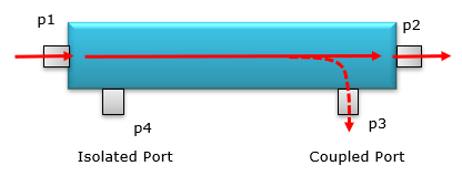
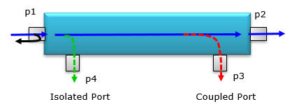
Operation of a regular directional coupler can be illustrated as below. The signal can flow only from p1 to p2 but cannot flow from p2 to p1. A certain portions of the signal can flow out of the p3 (Coupled Port), but cannot flow through p4 (Isolated Port).
Why we need a Circulator ?
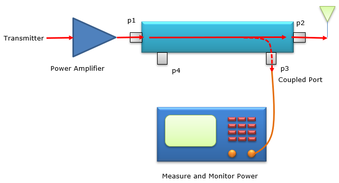
One of the most typical use case for the Circulator is as follows. You may connect the device on TX path (usually between Power Amplifier) and Antenna and measure / monitor the output power. If you use the coupler that output very small amount of the signal through the coupled port, you can monitor the output power without wasting much of the TX energy.
In my personal case, I often use this device connected to TX port of the protocol tester and measure the power while the test is running. One thing you need to keep in mind to use the device for this kind of purpose is to make it sure that the input power to the device should be relatively high, otherwise the power coming out of the coupled port is too low and spectrum analyzer would not display it propery.
Types of Directional Couplers.
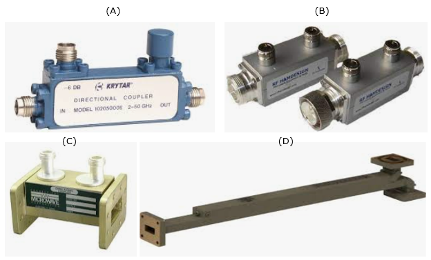
There are so many different types of directional couplers and some of the examples are shown below. (A), (B) are the common types that are frequently used in daily RF testing. (C),(D) are the waveguide types of the directional couples which would be used in very high frequency or high power.
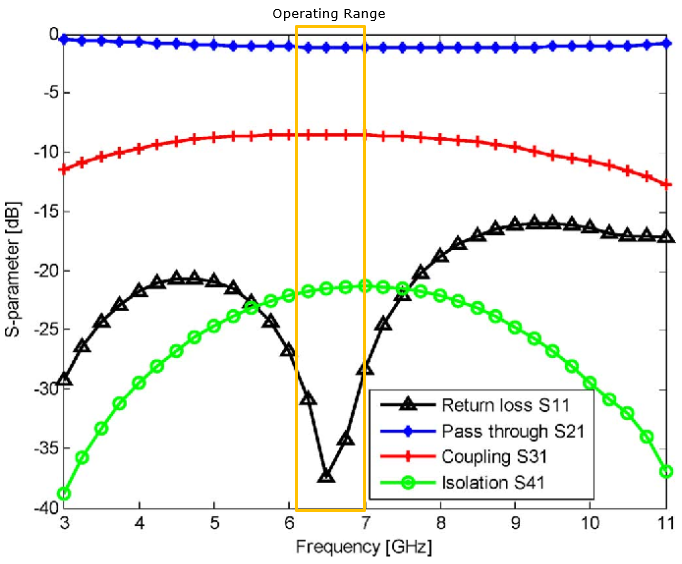
Typical Specification
I think the most important set of specification for a directional coupler can be summarized in a single s parameter graph as shown below. The important specification can be listed as below.
Graph Source : Cliick Here
|
||