|
RF |
||
|
Circulator
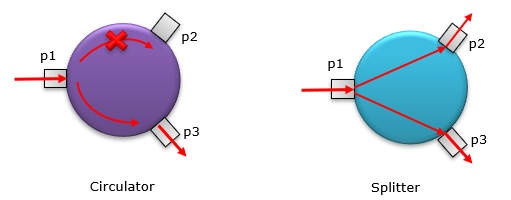
Circulator is a device that flows the input energy (wave, signal) through neighbouring port only in a specific direction. If you see the hardware of circulator, there are many cases where the circulator and the divider look similar. If you compare the circulator and splitter in illustration, it would be as shown below. As you may notice, in the circulator the input energy p1 follow through neigbouring port only on one side (p3 in this case) whereas in splitter, the input engergy(p1) devicided equally and flow though all the ports regardless of the position of the port.
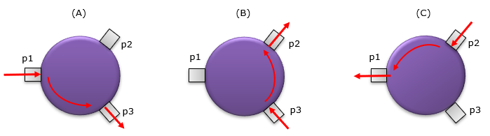
In most of circulator, any port can be used as an input port and any port can be used as output port. Which port become the output port is determined by which port is the input port. For example, let's take a look at following example. In this example, if you put the input to p1, the energy(wave, signal) goes out of p3 only (not through p2). If you put the input to p3, the energy(wave, signal) goes out of p2 only (not through p1). If you put the input to p2, the energy(wave, signal) goes out of p1 only (not through p3). It looks as if the energy is 'circling (circulating)' in only one direction.
Why we need a Circulator ?
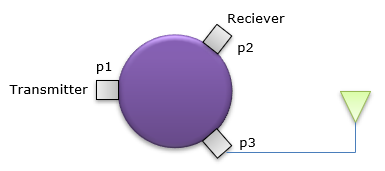
One of the most common use case of a circulator is illustrated as shown below. If you connect an antenna to a circulator (p3 in this example), you can make the transmitter signal (TX signal) and the reciever signal (RX signal) in separate port. That is, it can function as a duplexer.
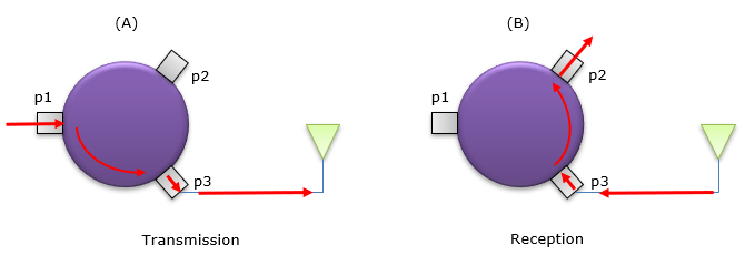
You may easily understand how this can work as a duplexer if you draw the path of the energy flow as shown below.
In my personal use case, I often use the circulator to separate Tx from Rx signal from TDD signal. When you measure TDD signal in spectrum analyzer, it is hard to figure out whether the captured signal is uplink signal or downlink signal. This cause even bigger problem if you want to setup a trigger. If you don't separate TX and RX, there would be many cases where the trigger you set for a TX signal gets triggered by RX signal and the other way around as well,
Types of Duplexers
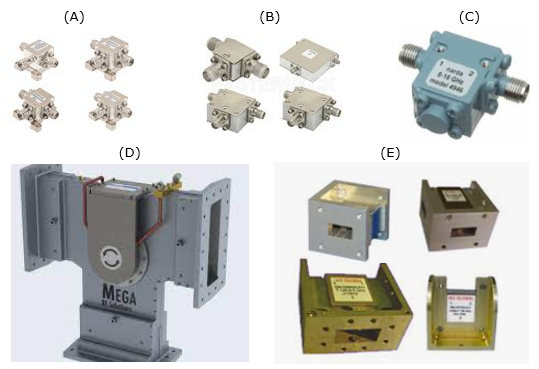
There are many different types of Circulator you can get in the market. You may get the types you would use in ordinary RF (e.g, A,B,C) and those waveguide type for super high frequeny or high power (e.g, D, E)
Typical Specification
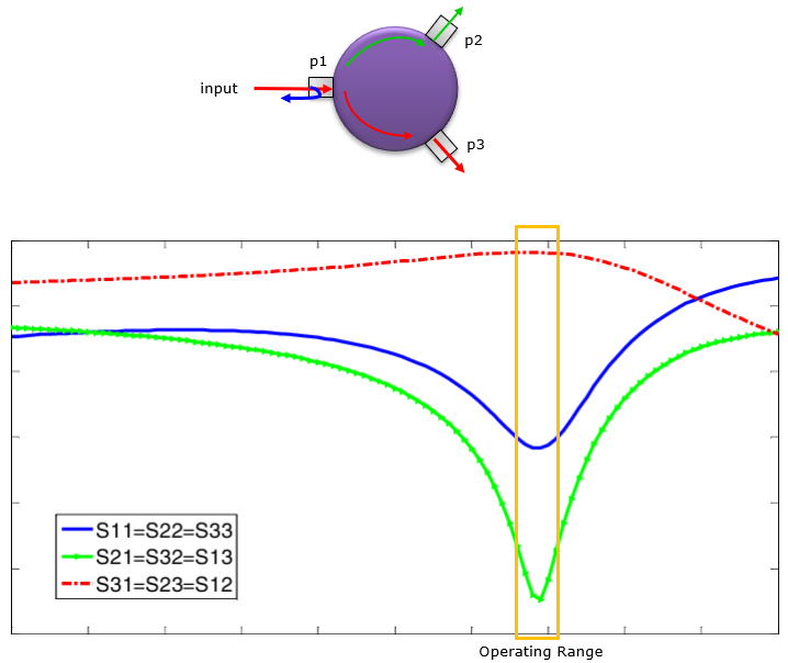
The typical specification for Isolator can easily be understood from s parameter graph as shown below. Let's assume that you want to use the circulator at the frequency range as in orange box. In some datasheet of the device, the manufacturer would provide plot like this, but sometimes they would provide the same information just as numbers at a certain frequency.
How wide frequency span it can operate as desired circulator : Ideally it is better if it covers infinate range of frequency span as the desired circulator. In every circulator like any other RF devices, it shows the desired performance only within a certain range of the frequency.
How much of the input power/energy/signal (p1 in this example) can be transferred to the desired output port(p3 in this example) : This is indicated by s31 (red line) in this example. Ideally 100% of p1 power should be transferred to p3 (i.e, p1 = p3) but this is impossible in reality. In reality, just the higher, the better.
How little of the input power/energy/signal (p1 in this example) can be transferred to the desired output port(p2 in this example) : This is indicated by s21 (green line) in this example. Ideally it should be 0 (-Infinity in the plot) but in reality, just the little the better.
How little of the input power/energy/signal (p1 in this example) bounce back (reflected back) to the input port(p1 in this example) : This is indicated by s11 (blue line) in this example. Ideally it should be 0 (-Infinity in the plot) but in reality, just the little the better.
Graph Source : Cliick Here
|
||