|
Mechanical Engineering |
||
|
Fluid Mechanics : Steady Flow Energy Equation (SFEE)
SFEE (Steady Flow Energy Equation) is an equation that describes the total engergy flows of an open system. It is assumed that the mass flow through the system is constant (this is why it is called 'Steady Flow Energy').
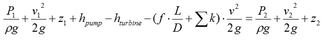
The SFEE is used to analyze a fluid flow across a piping system with the consideration of losses. Unlike Bernoulli’s equation Pump and turbine can be involved in SFEE, which are sources of work in the fluid flowing across a piping system SFEE assumes constant mass flow rate throughout the entire control volume.
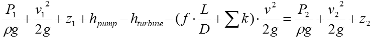
SFEE is a total head equation that express mechanical energy content in meters The equation states that the final mechanical energy content of a working fluid corresponds to the difference between the initial mechanical energy content and the total head loss when turbine and pump are not present SFEE does not account for interaction with surroundings, such as heat transfer
The exact SFEE for a specific system would varies depending on the structure of the system. In case of a typical piping system comprised of Pump, Turbine, Pipes. The SFEE can be expressed as follows :
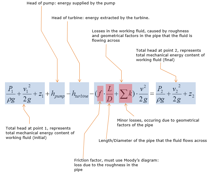
Let's think of the meaning of each term. Meaning of each term in the equation is commented as below.
Effects of Pump and Turbine on a kinetic fluid
Pump does work on the working fluid, supplying more mechanical energy to the working fluid Turbine extracts energy from a moving fluid to do useful work, such as generating electricity, which in turn decreases mechanical energy content (total head) of the working fluid
Let's suppose we have a very simple system which is made up of only a pump as shown below. Calculate the work in the unit of horse power that should be supplied by the pump to make this flow work.
Step 1 > Do some overall analysis and simplify the SFEE equation as much as possible.
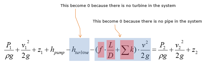
Since this can be regarded as a simplified 'Pump / Turbine / Pipe' system, we can apply the following SFEE.
Now let's think of how much we can simplify this equation. Since the system has pump only (no pipe, no turbine), we can remove following two terms.
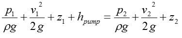
Then we get the simplified equation as below.
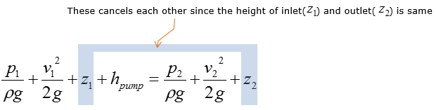
Using the information about the system, we can do simplification even further as below. (In this problem, we use the pump which has the height of inlet and outlet at the same level (or with neglible difference).
Now we get the simplified equation as below.
Step 2 > Rearrange the equation with the respect of the parameter that we need to calculate.
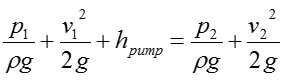
Rearrange the equation from Step 1, you can rewrite the SFEE of this system as follows.
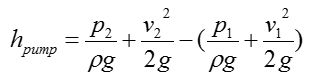
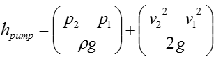
With a little bit further rearrangement, you can rewrite the equation as follows
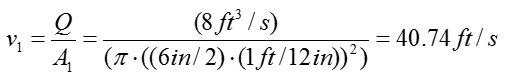
Step 3 > Calculate the velocity of the water flow at inlet and outlet
Check if you have all the information to calculate the equation from previous step. We have all the pressure information and given by the problem itself and the constants rho and g are known parameter even though it is not explicitely given by the problem itself. However, we don't have any information on the velocity of the water flow. But we can calculate the velocity as below since the amount water flow and the dimension of the pipe are given.
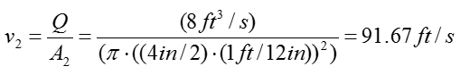
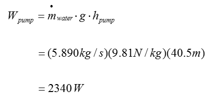
Step 4 > Calculate the pump head (h_pump)
Now we have all the information to calculate the following equation
Plugging in all the information into this equation, we can get the result as follows
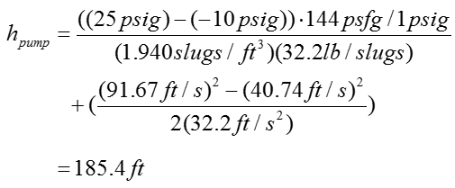
Example 2 >
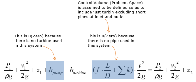
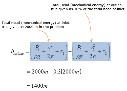
Water entering the chamber has a total head (mechanical energy) of 2,000m, where its mass flow rate is 30 kg/s. 70% of the total head is extracted by the turbine to operate the generator to produce electricity. What is the turbine head ?
< Image Source : http://www.reocities.com/CapeCanaveral/1706/turbine.html >
Solution >
Step 1 > Do some overall analysis and simplify the SFEE equation as much as possible.
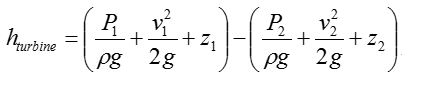
Step 2 > Calculate the turbine head (h_turbine)
Example 3 >
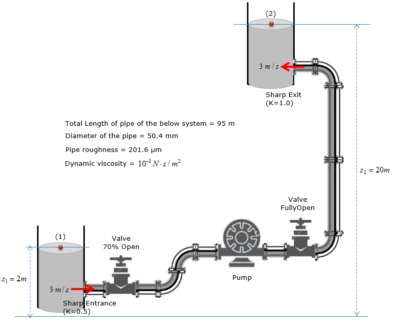
Estimate (Calculate) the head loss due to pipe friction in the system shown below ?
Step 1 : Calculate Reynold’s number of water following through the pipe
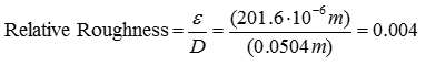
Step 2 : Calculate relative roughness of the pipe
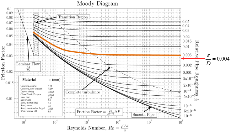
Step 3 : Highlight the entire curve closest to the relative roughness
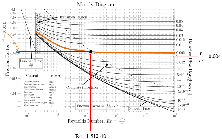
Step 4 : Extend vertical line from the Reynold’s Number(Re)
Step 5 : Extend horizontal line to the left from the dot and compute friction factor
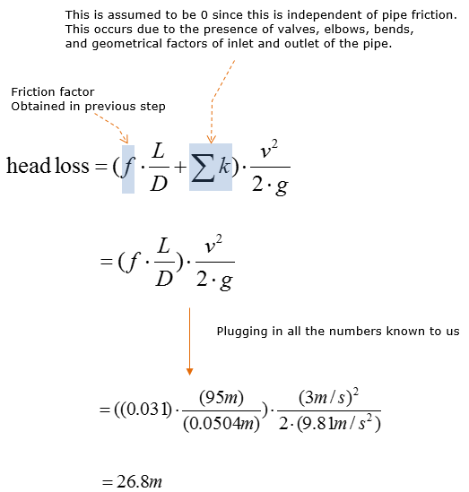
Step 6 : Calculate the head loss due to pipe friction
Example 4 >
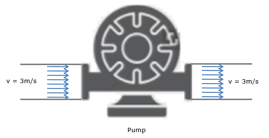
If the head loss in the system was found to be 20m, head loss due to the fittings was found to be 2.5m, the water velocity is 3m/s, the pipe diameter is 50mm, and both reservoirs are opened to atmosphere, how much pump power is required to sustain this flow?
The question can be re-written as follows.
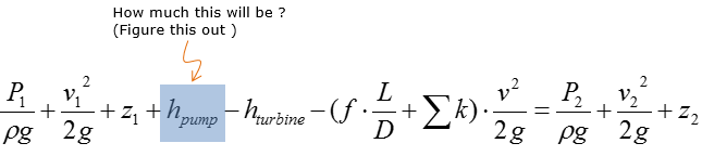
Step 1 > Apply SFEE to calculate the head of the pump
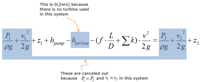
P1 and P2 are equal to zero, as water is exposed to the atmosphere. Assume identical water reservoirs, where the speed of change in water level are identical.
Then the SFEE above is simplified to the following:
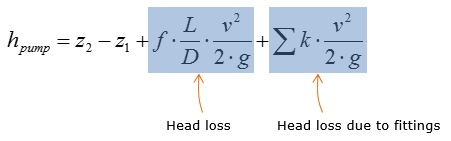
Rearrange the expression above for hpump
Plug in all the given parameters into the equation above
Step 2 > Calculate the mass flow rate along the pipe
Assume 1D velocity profile, where velocity does not vary over the radius of the cross-section of the pipe. No integral calculus is required to calculate the mass flow rate of water along the pipe. Neglect the elevational difference between the inlet and outlet of the pump
Step 3 > Determine the power that need to be generated by the pump
|
||