Physical Layer Problem Example - Timing Error
Most of wireless communication (practically every wireless communication that I know) works in very strictly synchronized timing between transmitter and reciever. This timing synchronization requirement tend to get more and more strict as you go with higher end communication technology like LTE. In most case to meet this kind of timing requirement tend to be one of the most challenging task but in most case you would not even realize that this kind of problem exists mainly because most of these problems get resolved at early stage of modem development. By the time the product gets at your hand as a user or as test engineer, these problem would not be noticeable.
However if you are really motivated enough to get the first hand experience with this, I would suggest you to get involved in verification of early stage of modem development.
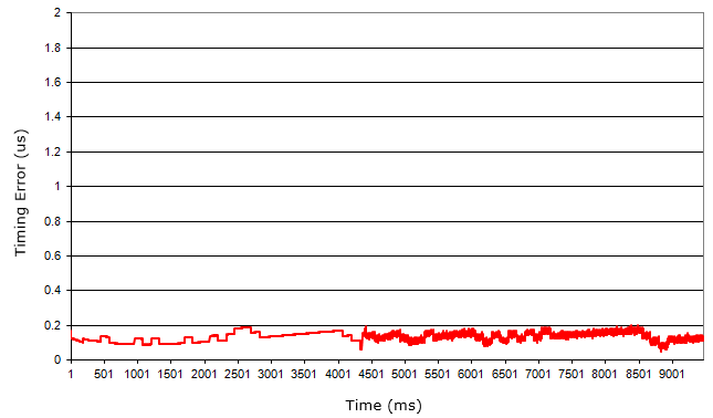
The issue is how to measure / detect this kind of timing error. Most of modem vendor and test equipment vendor provides a logging tools to print out this kind of timing error. If you process those log properly, you may plot the data as shown below.
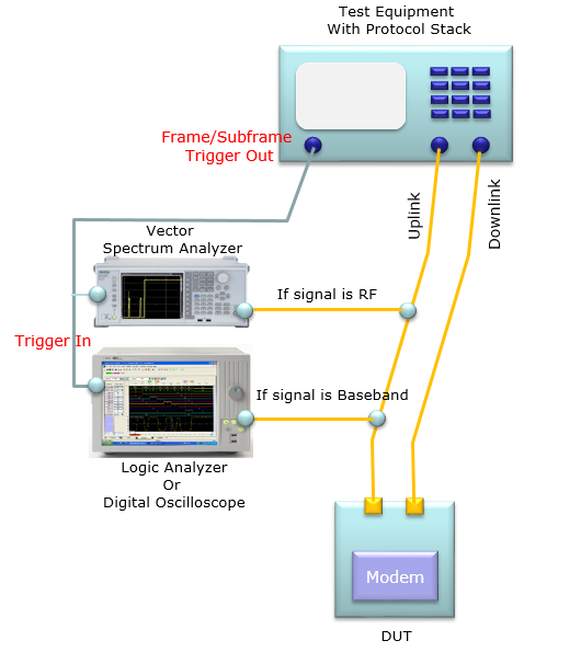
However, most of those logging tool measures the timing error at baseband from the demodulated data (or after decoding). It means that the input signal went in out of sync to such a degree that proper demodulation is not possible. This kind of logging tool would not help. This is the most challenging cases where you should handle. At this step, you would need some additional equipment to measure the timing error. Following is a conceptual test setup for timing error. This is just a conceptual, in real situation you would not connect Spectrum Analyzer and Logic Analyzer at the same time. If you have very high performance digital oscilloscope, you may use it both for baseband and RF. Also for the accurate measurement, you would need a protocol test equipment that can output a trigger signal at every subframe and every frame.
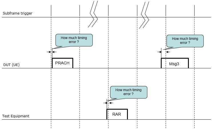
One of the most common case where you would be struggled by these timing error would be in RACH procedure. Following is one of the examples of timing error measurement that I really experienced (Sorry I am not supposed to open the specific numbers here). If you have issues with reception of any of these signal, you may first to check DUT log or equipment log to see if you can find any clue. However, if you don't find anything from those log, you need to draw following diagram (or capture) from the additional measurement equipment as shown above.
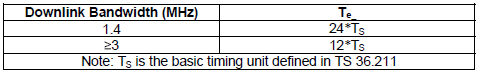
Whenever I bring up this kind of timing error issue, I am asked 'what is the requirement for the timing error / tolerance'. Since I get involved this kind of situation just around once or twice at early modem development testing, I often spend hours to find this information from 3GPP spec and forget about it. When I am get into the same situation after several month, I would spend a couple of hours again to find the same information. Now I decided to put down the specification in my note here. Following is timing error requirement from 3GPP. Most of the protocol test equipment would allow the timing error from a few to over a few tens of times wider than this specification so that it can maintain the connection with the DUT even when the timing error gets slightly out of the specification. However, how much timing error is allowed is completely up to test equipment (Uplink case) or DUT (Dowlink case).
< 36.133 - Table 7.1.2-1: Te Timing Error Limit >
How to fix this kind of timing error ?
This also depends on the degree of the error. If the error is not so big (i.e, at least within the range of demodulation), it may be corrected (compensated) by the baseband algorithm (e.g, at equalization at the reciever side). In this case, the problem may be fixed in a few days or in a few weeks. However, if the degree of error, you often need to design a special circuit (like additional FPGA) for the timing adjustment. If your DUT board or modem does not have this kind of large scale timing adjustment, it would take additional month to design and add such a additional circuit. In worst case, you would need to add this kind of timing adjustment circuit on both transmitter and reciever side.