CFI (Control Format Indicator)
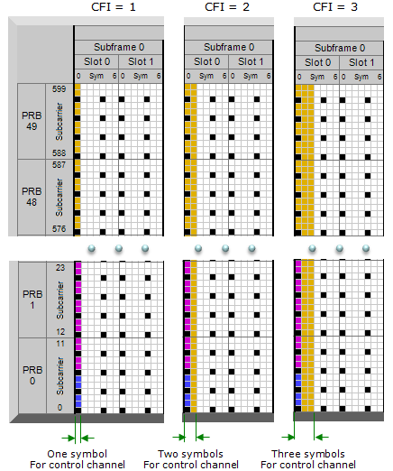
CFI is a indicator telling how many OFDM symbols are used for carrying control channel (e.g, PDCCH and PHICH) at each subframe. If CFI is set to be 1 for a subframe, it means one symbol (the first symbol) at the subframe is used for PDCCH allocation. If CFI is 2, it means two symbols (the first and the second symbol) are used for PDCCH. If CFI is 3, you know the answer -:)
(I created following subframe structure using LTE Resource Grid and edited to fit the topics of this page)
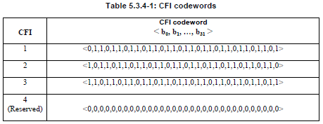
This CFI is carried by a specific physical channel called PCFICH. PCFICH is carrying only CFI without any other information. You may ask "why do we need a special physical channel carrying only one number ?". It is because CFI is made up of 31 bits data even though the types of the bit pattern is only 4. The bit pattern and the CFI value mapping is as follows (3GPP 36.212 5.3.4 Control format indicator).
< What would be the best CFI value ? >
Would there be any value that is the best for every subframe ? or for every situation ?
The answer would be No best value for every subframe and every situation.. but there can be some recommended value for a specific situation.
First, let's think about the general guide from 3GPP specification. We have a couple of different places of 3GPP specification mentioning about CFI.
First place is 3GPP 36.212 5.3.4 Control format indicator.. you can see following statement.
The CFI takes values CFI = 1, 2 or 3.
For system bandwidths with "Max Number of RBs for the System Bandwidth > 10", the span of the DCI in units of OFDM symbols, 1, 2 or 3, is given by the CFI.
For system bandwidths with "Max Number of RBs for the System Bandwidth <= 10", the span of the DCI in units of OFDM symbols, 2, 3 or 4, is given by CFI+1.
=> Basically this says.. you can specify any value of 1,2,3 in any bandwidth, but the conversion from 'CFI value' to 'number of OFDM symbols for the span of DCI' is different as follows.
Case 1 : For system bandwidths with "Max Number of RBs for the System Bandwidth > 10"
the number of OFDM symbols for the span of DCI = CFI Value
Case 2 : For system bandwidths with "Max Number of RBs for the System Bandwidth <= 10"
the number of OFDM symbols for the span of DCI = CFI Value + 1
According this rule, only System BW 1.4 Mhz is supposed to follow Case 2 rule and all other system BW is supposed to follow Case 1.
The description above would tell you the whole possible range of value of CFI, but does not tell you much about which value would be better than others.
You can find another guide lines in 4.3.3.3 Mapping of downlink physical channels and signals to physical resources of 36.508 as follows.
CFI = 3 for 1.4, 3 and 5 MHz system bandwidths
CFI = 2 for 10, 15 and 20 MHz system bandwidth
It seems to narrow down the value a little bit better for a couple of cases. It may be recommended well for most of the situation. However, if you are trying to achieve or test maximum throughput. You may have to think more carefully.
Large CFI value measn less space for PDSCH.. it means .. you would have higher code rate in the subframe with large CFI comparing to the subframe with low CFI value. You would also know that it would get more difficult for UE to decode PDSCH when Code Rate gets higher. According to my experience, the value specified in 36.508 works fine for most of the case including max throughput case in Cat 3 device. But in case of Cat 4 or higher, it would be harder to achieve max throughput with CFI value 2 or 3.. in this case most of UE fails at PDSCH decoding and report HARQ NACK causing PHY layer retransmission. So general tips for max throughput case would be "Use CFI = 1 for Cat 4 or higher max throughput case". If you want to see more quatative example for this description, refer to Is there any theoretical limit for Code Rate ? section of Code Rate page.
Then you may ask.. why don't we just set CFI = 1 for every case ?
Answer to this question is not as simple as you might have expected. The bottom line is 'you have to secure the minimum number of CCEs for the necessary PDCCH for each subframe'. If you set CFI to 1 in a very narrow bandwidth you may break this rule.
For the number of CCE required for number of PDCCH, refer to 36.213 Table 9.1.1-1. If you want to get more detailed explanation on CCE, PDCCH related issues, refer to following pages.
- Resource Allocation and Management Unit
- PDCCH Candidate and Search Space
- PDCCH Resource Allocation
- CCE Index Calculation/PDCCH Decoding/Blind
To many things to study just to figure out proper CFI number ?
True.. Simple rule of thumb is that you may easily set CFI value to 1 in case of 10 Mhz and higher bandwidth.. but in case of 5 Mhz and lower, you have to be very careful to check if the value meets the minimum number of CCE requirement. Since this requirement is influenced by phich-Resource IE in MIB and aggregation level, you have to consider those factors as well.