Arduino Home : www.sharetechnote.com
Arduino - Servo Motor
Servo Motor is a kind of motor that rotate back and forth within a certain angle (for example, 0~90, 0~180 or 0~360 degree). You can position the shaft of the motor at any angle within the specified range by sending control signal. They are most commony used in the application like the joint of Robot Arms which rotates within a certain range and require a relatively high torque.
What to buy ?
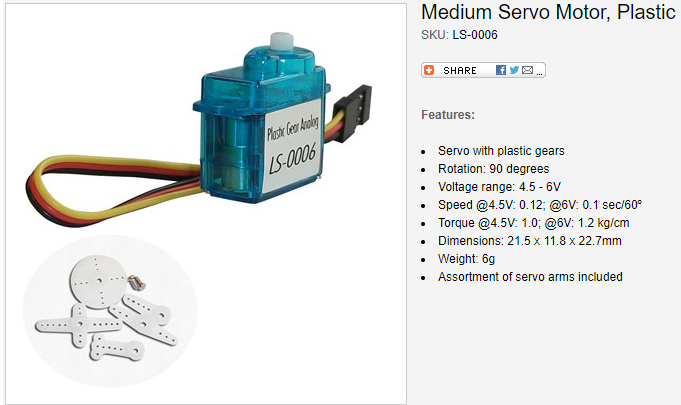
I used the Servo Motor called LS-0006 as shown below.
https://www.rpelectronics.com/ls-0006.html
How to Connect it to Arduino ?
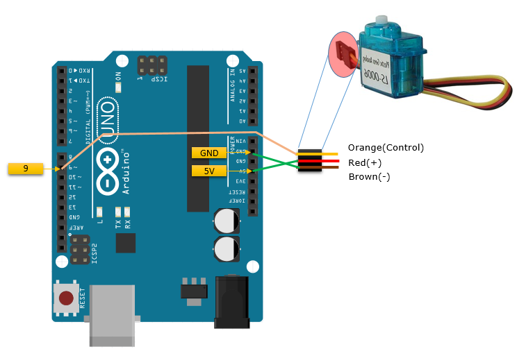
Controlling a servo motor with Arduino is simple and the cable connection is as simple as shown below. Most of the servo motors comes with 3 wires, which are Ground, (+) positive and Control. Depending on the motor, the color coding of wires would vary a little bit, so it is very important to find out which pin (color) is Ground, Positive or Control.
The Servo Motor that I used in this tutorial is a very small one called LS-0006, the wire connections are as shown below. As you see here, I don't use any extra power source to drive the motor. Most of the small servo motors would not require any external power source, but you would need external power supply circuit if you want to use a large scale Servo Motor (NOTE : I would not directly connect the motor if it consumes more than 400 mA. Refer to Electrical Specification of Arduino for further details)
Running a Sample Code
Once you have connected the servo motor as shown above, open the sample program as shown below.
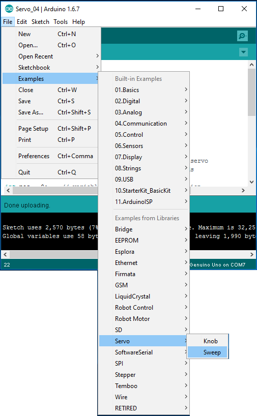
You may try running the sample code as it is, but I modified the code a little bit because the range of the rotation for my motor is 0~90 degree but the sample code is written to operate the motor within the range of 0~180 degree.
#include <Servo.h>
Servo myservo;
int pos = 0;
int maxAngle = 90;
void setup() {
myservo.attach(9);
}
void loop() {
for (pos = 0; pos <= maxAngle; pos += 1) {
myservo.write(pos);
delay(15);
}
for (pos = maxAngle; pos >= 0; pos -= 1) {
myservo.write(pos);
delay(15);
}
}
I seems that sample code provided by Arduino IDE works pretty well for any Servo Motor. However, for study purpose you may try and play with following experimenal codes to make it work for the motor that you are using. This experimental code would make your motor in some way, but it would not make it move as accurately as in the sample code above. You need to tweak the numbers and change sequences in the experimental code a lot to make it work as you expected. However, it would be good for you to learn the details of control signal for your motor.
Experiment 1 >
#include <Servo.h>
Servo myservo;
int pos = 0;
void setup() {
myservo.attach(9);
}
void loop() {
myservo.writeMicroseconds(500);
delay(1000);
myservo.writeMicroseconds(1000);
delay(1000);
myservo.writeMicroseconds(1500);
delay(1000);
}
Experiment 2 >
int ControlPin = 9;
int tick = 5;
int tickMax = 1;
int pulseWidth = 0; // in microseconds
int pulsePeriod = 20000; // in microseconds
void setup() {
pinMode(ControlPin, OUTPUT);
}
void loop() {
pulseWidth = 500;
for(tick = 0; tick <= tickMax; tick += 1)
{
digitalWrite(ControlPin,HIGH);
delayMicroseconds(pulseWidth);
digitalWrite(ControlPin,LOW);
delayMicroseconds(pulsePeriod-pulseWidth);
};
delay(3000);
pulseWidth = 1500;
for(tick = 0; tick <= tickMax; tick += 1)
{
digitalWrite(ControlPin,HIGH);
delayMicroseconds(pulseWidth);
digitalWrite(ControlPin,LOW);
delayMicroseconds(pulsePeriod-pulseWidth);
};
delay(3000);
pulseWidth = 2000;
for(tick = 0; tick <= tickMax; tick += 1)
{
digitalWrite(ControlPin,HIGH);
delayMicroseconds(pulseWidth);
digitalWrite(ControlPin,LOW);
delayMicroseconds(pulsePeriod-pulseWidth);
};
delay(3000);
}
Reference :