NR RLC is almost same as LTE RLC. So if you are already faimiliar with LTE RLC, you wouldn't need much of extra study to understand NR RLC. If you are new to overall functionality of RLC, I would suggest you to go through LTE RLC page first. Since I wouldn't see any NR test equipment and UE in near future, I wouldn't be able to put much of practical information on NR RLC until the equipment and UE are available. Your knowledge on LTE RLC would help you understand NR RLC.
Actually a large portions of the contents on this page comes from the direct copy of LTE RLC page and I would try to highlight those parts which is unique to NR RLC.
- Overview / Overall Functionality
- TM Mode / Procedure
- UM Mode / Procedure
- AM Mode / Procedure
- RLC Data Structure
- RRC Parameters defining RLC
Overview / Overall Functionality
As in LTE and WCDMA, NR RLC has three different mode : TM(Transparent Mode), UM(Unacknowledge Mode) and AM(Acknowledge mode). The details of each of these mode will be described later, but the very brief summary of key features of these mode is as follows :
- TM : No RLC Header, Buffering at Tx only, No Segmentation/Reassembly, No feedback (i.e, No ACK/NACK)
- UM : RLC Header, Buffering at both Tx and Rx, Segmentation/Reassembly, No feedback(i.e, No ACK/NACK)
- AM : RLC Header, Buffering at both Tx and Rx, Segmentation/Reassembly, Feedback(i.e, ACK/NACK)
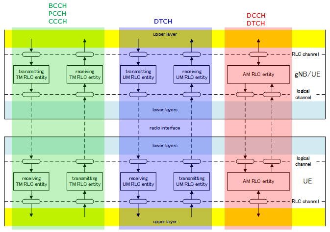
Each of these mode can both transmit and receive data. In TM and UM, separate entity is used for transmission and reception, but in AM a single RLC entity perform both transmission and reception as illustrated below.
One important thing you need to pay attention to is that each of logical channels use a specific RLC mode as shown below.
- BCCH, PCCH, CCCH use RLC TM only.
- DCCH use RLC AM only.
- DTCH use RLC UM or AM. (Which mode is used for each DTCH channel ? This is determined by RRC message).
Now let's look into a little bit further details on how data is processed by each RLC Mode. Since each RLC mode is associated with a specific set logical channels, I would suggest you to associate this RLC mode procedure to RLC layer processing mechanism for each of those channels.
TM Mode / Procedure
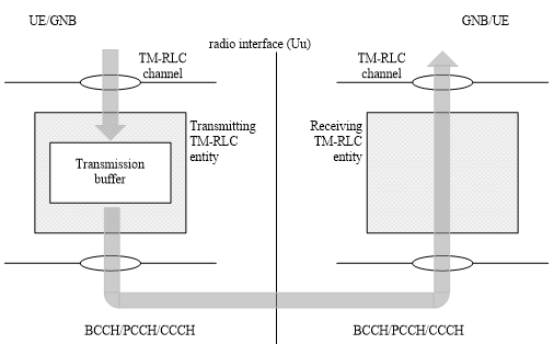
As you see in the following illustration. TM mode would mean 'almost no processing to RLC data'. The only thing it does is to buffer data on Tx side. There is no RLC header, No reordering, no segmentation, no reassembly is happening in this layer. Because of this 'no data processing' nature of TM mode, if you compare the RLC input and RLC output data of TM mode, you would see no difference between the two.
One important thing to keep in mind is that you need to pay attention to MAC/PHY resource allocation. Even if MAC/PHY resource is allocated smaller than the RLC packet, the RLC wouldn't care. It would just forward whatever it has to MAC/PHY. So those RLC data bigger than MAC/PHY resource may be chopped off or discarded.
Again another this to be noticed is that the local channel BCCH / PCCH / CCCH data is processed by this RLC mode.
< 38.322 - Figure 4.2.1.1.1-1: Model of two transparent mode peer entities >
UM Mode / Procedure
Next, let's look into UM mode. UM stands for 'Unacknowledged Mode'. 'Unacknowledged Mode' means 'it does not require any reception response from the other party'. 'Reception response' simply mean 'ACK' or 'NACK' from the other party. (UM mode is similar to TM mode in that it does not require any ACK/NACK from the other party, but it is different from TM in that I has it's own header)
What is the difference between UM mode and TM mode we saw above ? It seems that UM mode is doing more operation than TM mode.
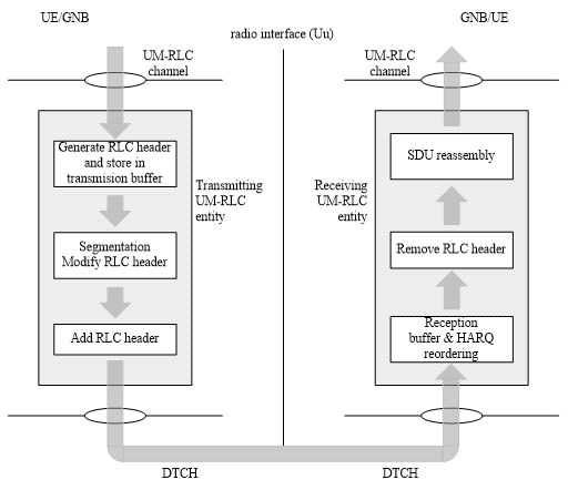
What kind of operation UM mode do ? You can just 'read' diagram for the answer. The answer would be a little bit different with transmitter side and reciever side.
Let's read the operation on transmitting side first. If you just read (verbalize) the diagram
i) Buffering the data and generate RLC Header.
ii) Segmetation (Split a big chunk into a multiple small chunk) and Modify RLC Header (Some field in RLC header should be changed based on the segmentation status)
iii) Add RLC header
From RAN2 NR#1:
- Working assumption on no RLC concatenation taken at RAN2#96 is confirmed (i.e., concatenation of RLC PDUS is performed in MAC).
Then, read the operation on recieving side. If you just read (verbalize) the diagram
i) Buffering
ii) Reordering (Sometimes the chunks transmitted earlier from transmitter may arrive late at the reciever. In this case you have to reorder the incoming chunks into proper order for reassembly).
iii) Remove the RLC header (you would remember that the transmitter put the header to each of the chunk. So you have to remove this before you reassemble the data).
iv) Reassembly
< 38.322 - Figure 4.2.1.2.1-1: Model of two unacknowledged mode peer entities >
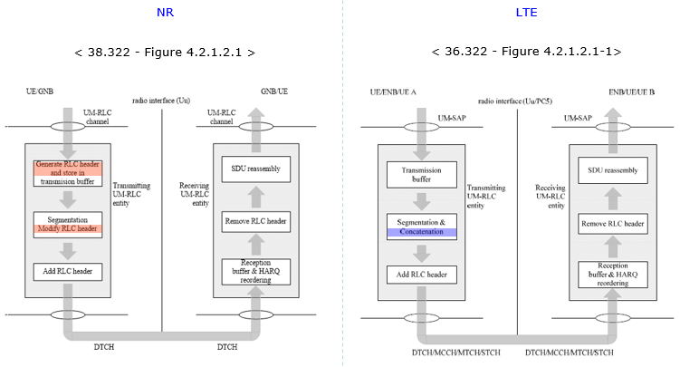
For those who already familiar with LTE RLC, I put the NR RLC UM and LTE RLC UM side by side for comparision. You see there is no difference in reciver side operation, but there is some difference in transmitter side. The most important difference in transmitter side is that NR RLC UM does not perform 'Concatenation' process.
AM Mode / Procedure
Now let's look at AM mode which is the most complicated RLC type. 'AM' stands for 'Acknowledge Mode'. As it's name implies it requires ACK/NACK from the other party. It is more like TCP packet in IP world, whereas RLC UM is more like UDP in IP world.
Is it expecting the ACK/NACK for every transmission ? If it is the case, isn't it too much overhead ? Good question. Yes.. it is too much overhead. That's why we have RLC window concept (like TCP Window in IP traffic) and Polling bit concept and all sorts of ACK/NACK scheduling mechanism which makes it extremely difficult to understand full details of RLC AM operation. (This kind of detailed procedure would not be explained now.. but not sure by when I can get to the level of details -:)
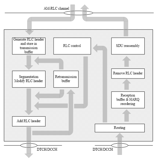
Now just look into the diagram from the specification. If you go through the left column and the right colum, you will see the same procedures you saw in UM mode. so I don't want to verbalize that part again. What is different from UM mode lies in the middle column, namely 'Retransmission buffer' and 'RLC control' procedure.
Let's just follow the arrrows. What is coming into the retransmission buffer ? i.e, what is the input to the retransmission buffer ?
After RLC transmitter do the segmentation/concatenation process, it adds RLC header and then it creates two identical copies and transmit the one copy of the data out to lower layer (MAC) and send another copy to Retransmission buffer.
If the RLC get Nack or does not get any response from the other party for a certain period of time, the RLC packet (we call this RLC PDU) in the retransmission buffer gets transmitted again. If the RLC get ACK, the ones in retransmission buffer would be discarded.
< 38.322 - Figure 4.2.1.3.1-1: Model of an acknowledged mode entity >
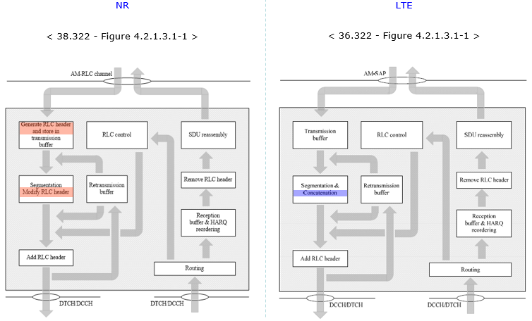
For those who already familiar with LTE RLC, I put the NR RLC AM and LTE RLC AM side by side for comparision. You see there is no difference in reciver side operation, but there is some difference in transmitter side. The most important difference in transmitter side is that NR RLC AM does not perform 'Concatenation' process.
RLC Data Structure
TMD Data Structure
< 38.322-Figure 6.2.2.2-1: TMD PDU >
UMD Data Structure
There are various types of UMD PDU as illustrated below.
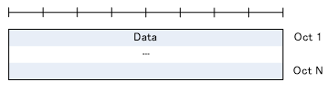
First type is the one shown below. The RLC header has only SI field and R field and has no SN field. 38.322-6.2.2.3 states "When an UMD PDU contains a complete RLC SDU, the UMD PDU header only contains the SI and R fields. An UMD PDU header contains the SN field only when the corresponding RLC SDU is segmented."
< 38.322-Figure 6.2.1.3-1: UMD PDU containing a complete RLC SDU >
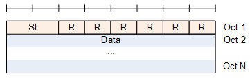
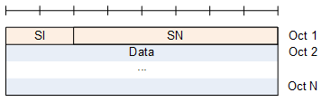
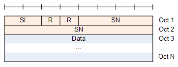
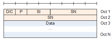
Second type is the ones shown below. This type carries SN field. The length of SN field is 6 or 12 bits. Which one to be used is determined by RRC Configuration SN-FieldLengthUM. This type does not carry SO (Segment Offset) field. 38.322-6.2.2.3 states "An UMD PDU carrying the first segment of an RLC SDU does not carry the SO field in its header."
< 38.322-Figure 6.2.2.3-2: UMD PDU with 6 bit SN (No SO) >
< 38.322-Figure 6.2.2.3-3: UMD PDU with 12 bit SN (No SO) >
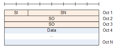
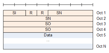
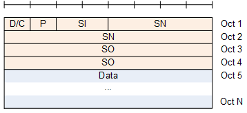
Third type is the ones shown below. It carries SI,SN and SO. The existence of SO indicates that this PDU carries a segment of an SDU and the segment is NOT the first segment. (If it is the first segment, SO field would not be carried).
< 38.322-Figure 6.2.2.3-4: UMD PDU with 6 bit SN and with SO >
< 38.322-Figure 6.2.2.3-5: UMD PDU with 12 bit SN and with SO >
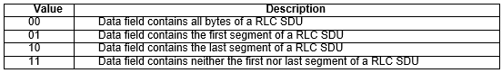
< 38.322-Table 6.2.2.4-1: SI field interpretation >
AMD Data Structure
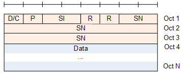
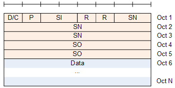
RLC AM PDU structure is illustrated below. D/C, P, SI are common to every types of AM PDU. The main difference is the length of SN field and the existence of SO field.
Following type carries SN field but does not carry SO(Segment Offset) field. It mean that this PDU non-segmented SDU(a complete SDU) or the first segment of a segmented SDU.
The length of SN field can be 12 or 18 bits. Which one to use is determined by RRC parameter : SN-FieldLengthAM.
< 38.322-Figure 6.2.1.4-1: AMD PDU with 12 bit SN (No SO) >
< 38.322-Figure 6.2.1.4-2: AMD PDU with 18 bit SN (No SO) >
The second type of AMD PDU carries SO as illustrated below. It mean that this PDU carries a Non-First segment of a segmented SDU. The length of SO field is always 16 bits.
< 38.322-Figure 6.2.1.4-3: AMD PDU with 12 bit SN with SO >
< 38.322-Figure 6.2.1.4-4: AMD PDU with 18 bit SN with SO >
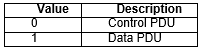
< 38.322-Table 6.2.2.6-1: D/C field interpretation >
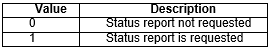
< 38.322-Table 6.2.2.7-1: P field interpretation >
< 38.322-Table 6.2.2.4-1: SI field interpretation >
STATUS PDU
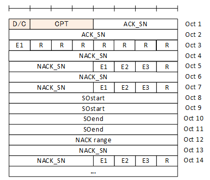
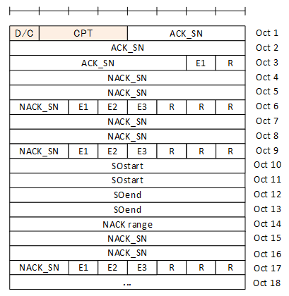
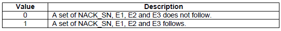
Status PDU is used to carry various RLC control information like ACK sequence Number, NACK sequence number or the exact location of the NACK in the unit of Bytes etc. The full stucture of Status PDU is as follows, but only D/C, CPT, ACK_SN field are always present and other fields may or may not present depending on situation. The receiving side of RLC can figure out whether thse additional fields (e.g, NACK SN, SO, NACK range etc) by checking the extention field (E1, E2, E3) which will be explained later.
< 38.322-Figure 6.2.2.5-1: STATUS PDU with 12 bit SN >
< 38.322-Figure 6.2.2.5-2: STATUS PDU with 18 bit SN >
< 38.322 - Table 6.2.3.11-1: E1 field interpretation >
< 38.322 - Table 6.2.3.13-1: E2 field interpretation >

< 38.322 - Table 6.2.3.16-1: E3 field interpretation >

RRC Parameters defining RLC
RLC-BearerConfig ::= SEQUENCE {
logicalChannelIdentity LogicalChannelIdentity,
servedRadioBearer CHOICE {
srb-Identity SRB-Identity,
drb-Identity DRB-Identity
} OPTIONAL, -- Cond LCH-SetupOnly
reestablishRLC ENUMERATED {true} OPTIONAL, -- Need R
rlc-Config RLC-Config OPTIONAL, -- Cond LCH-Setup
mac-LogicalChannelConfig LogicalChannelConfig OPTIONAL, -- Cond LCH-Setup
...
}
RLC-Config ::= CHOICE {
am SEQUENCE {
ul-AM-RLC UL-AM-RLC,
dl-AM-RLC DL-AM-RLC
},
um-Bi-Directional SEQUENCE {
ul-UM-RLC UL-UM-RLC,
dl-UM-RLC DL-UM-RLC
},
um-Uni-Directional-UL SEQUENCE {
ul-UM-RLC UL-UM-RLC
},
um-Uni-Directional-DL SEQUENCE {
dl-UM-RLC DL-UM-RLC
},
...
}
UL-AM-RLC ::= SEQUENCE {
sn-FieldLength SN-FieldLengthAM OPTIONAL, -- Cond Reestab
t-PollRetransmit T-PollRetransmit,
pollPDU PollPDU,
pollByte PollByte,
maxRetxThreshold ENUMERATED { t1, t2, t3, t4, t6, t8, t16, t32 }
}
DL-AM-RLC ::= SEQUENCE {
sn-FieldLength SN-FieldLengthAM OPTIONAL, -- Cond Reestab
t-Reassembly T-Reassembly,
t-StatusProhibit T-StatusProhibit
}
UL-UM-RLC ::= SEQUENCE {
sn-FieldLength SN-FieldLengthUM OPTIONAL -- Cond Reestab
}
DL-UM-RLC ::= SEQUENCE {
sn-FieldLength SN-FieldLengthUM OPTIONAL, -- Cond Reestab
t-Reassembly T-Reassembly
}
SN-FieldLengthUM ::= ENUMERATED {size6, size12}
SN-FieldLengthAM ::= ENUMERATED {size12, size18}
T-PollRetransmit ::= ENUMERATED {
ms5, ms10, ms15, ms20, ms25, ms30, ms35,
ms40, ms45, ms50, ms55, ms60, ms65, ms70,
ms75, ms80, ms85, ms90, ms95, ms100, ms105,
ms110, ms115, ms120, ms125, ms130, ms135,
ms140, ms145, ms150, ms155, ms160, ms165,
ms170, ms175, ms180, ms185, ms190, ms195,
ms200, ms205, ms210, ms215, ms220, ms225,
ms230, ms235, ms240, ms245, ms250, ms300,
ms350, ms400, ms450, ms500, ms800, ms1000,
ms2000, ms4000, spare5, spare4, spare3,
spare2, spare1}
PollPDU ::= ENUMERATED {
p4, p8, p16, p32, p64, p128, p256, p512, p1024, p2048, p4096,
p6144, p8192, p12288, p16384, p20480, p24576, p28672, p32768,
p40960, p49152, p57344, p65536, infinity, spare8, spare7, spare6,
spare5, spare4, spare3, spare2, spare1}
PollByte ::= ENUMERATED {
kB1, kB2, kB5, kB8, kB10, kB15, kB25, kB50, kB75,
kB100, kB125, kB250, kB375, kB500, kB750, kB1000,
kB1250, kB1500, kB2000, kB3000, kB4000, kB4500,
kB5000, kB5500, kB6000, kB6500, kB7000, kB7500,
mB8, mB9, mB10, mB11, mB12, mB13, mB14, mB15,
mB16, mB17, mB18, mB20, mB25, mB30, mB40, infinity,
spare20, spare19, spare18, spare17, spare16,
spare15, spare14, spare13, spare12, spare11,
spare10, spare9, spare8, spare7, spare6, spare5,
spare4, spare3, spare2, spare1}
T-Reassembly ::= ENUMERATED {
ms0, ms5, ms10, ms15, ms20, ms25, ms30, ms35,
ms40, ms45, ms50, ms55, ms60, ms65, ms70,
ms75, ms80, ms85, ms90, ms95, ms100, ms110,
ms120, ms130, ms140, ms150, ms160, ms170,
ms180, ms190, ms200, spare1}
T-StatusProhibit ::= ENUMERATED {
ms0, ms5, ms10, ms15, ms20, ms25, ms30, ms35,
ms40, ms45, ms50, ms55, ms60, ms65, ms70,
ms75, ms80, ms85, ms90, ms95, ms100, ms105,
ms110, ms115, ms120, ms125, ms130, ms135,
ms140, ms145, ms150, ms155, ms160, ms165,
ms170, ms175, ms180, ms185, ms190, ms195,
ms200, ms205, ms210, ms215, ms220, ms225,
ms230, ms235, ms240, ms245, ms250, ms300,
ms350, ms400, ms450, ms500, ms800, ms1000,
ms1200, ms1600, ms2000, ms2400, spare2, spare1}
Reference
[1]