|
|
||
|
In a big picture, the power control of 3G(WCDMA/HSPA) , 4G(LTE) and 5G(NR) are almost same. If you have a good understandings on power control concept and mechnisnm of 3G or 4G, you will not have much difficulties in understanding 5G power control. If you are not familiar with the power control concept and mechanism, I would suggest you to read LTE Power control page since I write a lot of basic concept in the page and then read this page. (It is not required, but it will be good to read 3G power control page as well). As in 3G and 4G, in 5G as well Power Control happens in two different mode. One is Open Loop Control and the other is Closed Loop Control. Simply put, Open Loop Control is a mechnism to determin PRACH transmission power and Closed Loop Control is a mechanism of PUCCH or PUSCH channel power while a UE is in communication (connection) stage. In reality, it would be almost impossible for you to manually calculate the exact power as described in the specification unless you are the baseband and RF firmware engineer who need to implement the power control algorithm. There are so many parameters involved in this process. What we can do is just to get some big picture of the algorithm and understand what kind of factors are involved.
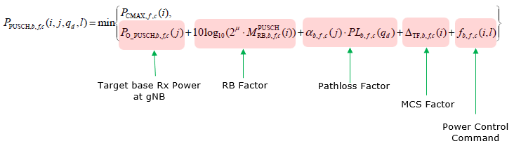
Main Factors for Power Control/Big PicturePower Control details are more complicated than you may think. Math formula looks so complicated and 3GPP description is confusing. So if you jump into the 3GPP spec and math expression, you may easily get lost just by reading a few lines of the specification. You might have similar experience in studying LTE power control specification, but 5G got even worse :) meaning more complicated. But regardless of 4G or 5G, general idea and overall structure of power control formual are similar. Ideally I think I can summarize the equation for Tx Power (UE Tx Power) of any uplink channel can be summarized as below. Tx Power = Target Rx Power set by gNB + PathLoss factor + MCS factor + RB factor + Power Control Command
A short description of each of the terms in this math expression are :
Next step is to figure out which of these factors gets involved in estimating the Tx Power of a specific physical channel (it implies that not all of these factors are used for every type of physical channel). For example,
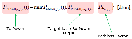
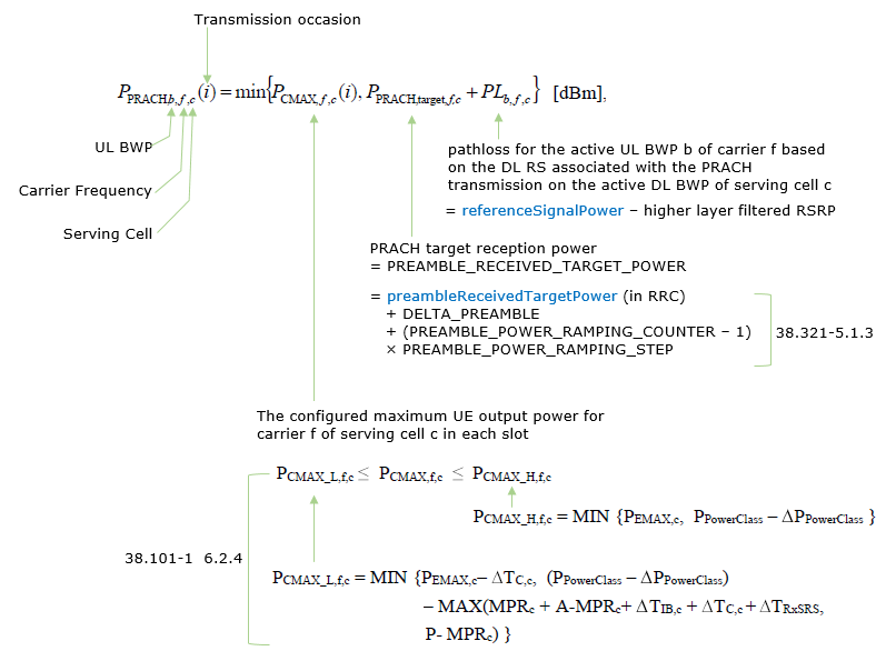
For PRACH transmission power, the value of each of the factors would be For PUSCH transmission power, the value of each of the factors would be How PRACH Power is determined ?Main part of PRACH power is defined in 38.213-7.4 as follows and you need to refer to several other specification for complete understanding of the equation. Before jumping to the details of PRACH power calculation, let's just take a big picture of the equation as explained previous section. Overall structure of the equation can be highlighted as follows and you should be able to get the high level understanding as below. If you have difficulties with interpretation of this, check out the explanation in previous section again.
With one step deeper ino the equation, it simply says i) Calculate P_PRACH,target,f,c + PL_b,f,c ii) Compare the calculated power(P_PRACH,target,f,c + PL_b,f,c) with P_CMAX,f,c iii) If the calculated power(P_PRACH,target,f,c + PL_b,f,c) is greater than P_CMAX,f,c, use P_CMAX,f,c. If the calculated poewr is lower than P_CMAX,f,c, then use the calculated power. Sound simple ? Yes, it only SOUND Simple.. not really simple because the calculation of P_PRACH,target,f,c is pretty complicated as explained in this page and it involves many lower layer parameters which is not readily open to you.
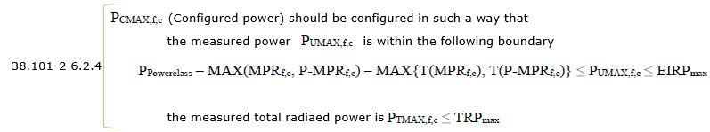
Power Class and Max PowerPower Class (P_PowerClass) and the Mas power allowed for the power class varies depending on Freuqency range (FR1 or FR2) and each specific band. Check out this note for the details. Determination of referenceSignalPowerThe description in this section is largely based on 38.213 - 7.4. As you might have guessed, ss-PBCH-BlockPower is fundamental reference signal for every cases. Only in some special cases CSI RS Power (PowerControlOffsetSS) is used.
Then, referenceSignalPower is determined by ss-PBCH-BlockPower
Then, referenceSignalPower is determined by ss-PBCH-BlockPower
Then, referenceSignalPower is determined by ss-PBCH-BlockPower and powerControlOffsetSS , where powerControlOffsetSS (in RRC) is an offset of CSI-RS transmission power relative to SS/PBCH block transmission power. if powerControlOffsetSS is not provided by RRC, UE assumes that this value is 0 dB Determination of PREAMBLE_RECEIVED_TARGET_POWERPREAMBLE_RECEIVED_TARGET_POWER is determined by following equation (38.321 - 5.1.3) PREAMBLE_RECEIVED_TARGET_POWER = preambleReceivedTargetPower (in RRC) + DELTA_PREAMBLE + (PREAMBLE_POWER_RAMPING_COUNTER 1) PREAMBLE_POWER_RAMPING_STEP
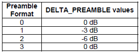
< 38.321 V15.3.0 - Table 7.3-1: DELTA_PREAMBLE values for long preamble formats. >
< 38.321 V15.3.0 - Table 7.3-2: DELTA_PREAMBLE values for short preamble formats. >
Example of RRC Configuration :This is an example of SIB1 configuration with IEs highlighted in red which are related te PRACH transmission power determination.
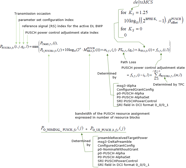
{ message c1: cellSelectionInfo { q-RxLevMin -70, q-QualMin -20 }, cellAccessRelatedInfo { ... }, connEstFailureControl { ... }, servingCellConfigCommon { downlinkConfigCommon { frequencyInfoDL { ... }, initialDownlinkBWP { genericParameters { ... }, pdcch-ConfigCommon setup: { ... }, pdsch-ConfigCommon setup: { ... } }, bcch-Config { ... }, pcch-Config { ... } }, uplinkConfigCommon { frequencyInfoUL { ... }, initialUplinkBWP { genericParameters { ... }, rach-ConfigCommon setup: { rach-ConfigGeneric { prach-ConfigurationIndex 160, msg1-FDM one, msg1-FrequencyStart 3, zeroCorrelationZoneConfig 15, preambleReceivedTargetPower -110, preambleTransMax n7, powerRampingStep dB4, ra-ResponseWindow sl20 }, ssb-perRACH-OccasionAndCB-PreamblesPerSSB one: n8, ra-ContentionResolutionTimer sf64, prach-RootSequenceIndex l139: 1, msg1-SubcarrierSpacing kHz30, restrictedSetConfig unrestrictedSet }, pusch-ConfigCommon setup: { pusch-TimeDomainAllocationList { { k2 7, mappingType typeA, startSymbolAndLength 27 }, { k2 4, mappingType typeA, startSymbolAndLength 27 }, { k2 5, mappingType typeA, startSymbolAndLength 27 } }, }, pucch-ConfigCommon setup: { pucch-ResourceCommon 11, pucch-GroupHopping neither, p0-nominal -90 } }, timeAlignmentTimerCommon infinity }, ssb-PositionsInBurst { ... }, ssb-PeriodicityServingCell ms20, tdd-UL-DL-ConfigurationCommon { ... }, }, ue-TimersAndConstants { ... } } } How msg3 Power is determined ?msg3 Power is determined by following equation. As shown here, msg3 Power is based on msg1 Power(PRACH Power) with some offset values on top of it. It implies that msg3 power is also controlled by Open Loop Power Control mechanism like msg1(PRACH). This is based on 38.213-7.1.1 msg3 Power = preambleReceivedTargetPower + (2 x msg3-DeltaPreamble) How PUSCH Power is determined ?Before jumping to the details of PRACH power calculation, let's just take a big picture of the equation as explained previous section. Overall structure of the equation can be highlighted as follows and you should be able to get the high level understanding as below. If you have difficulties with interpretation of this, check out the explanation in previous section again.
Detailed description on PUSCH power calculation is depicted as below. Some highlights are :
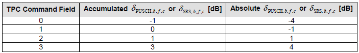
< 38.213 - Table 7.1.1-1: Mapping of TPC Command Field in a DCI format scheduling a PUSCH transmission, or in DCI format 2_2 with CRC scrambled by TPC-PUSCH-RNTI, or in DCI format 2_3, to absolute and accumulated δ_PUSCH,b,f,c values or δ_SRS,b,f,c values >
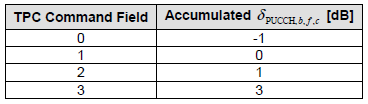
< 38.213 - Table 7.2.1-1: Mapping of TPC Command Field in a DCI format to accumulated δ_PUCCH,b,f,c values >
Example of RRC Configuration :This is an example of SIB1 and RRC Setup configuration with IEs highlighted in red which are related te PUSCH transmission power determination.
{ message c1: cellSelectionInfo { q-RxLevMin -70, q-QualMin -20 }, cellAccessRelatedInfo { ... }, connEstFailureControl { ... }, servingCellConfigCommon { downlinkConfigCommon { frequencyInfoDL { ... }, initialDownlinkBWP { genericParameters { ... }, pdcch-ConfigCommon setup: { ... }, pdsch-ConfigCommon setup: { ... } }, bcch-Config { ... }, pcch-Config { ... } }, uplinkConfigCommon { frequencyInfoUL { ... }, initialUplinkBWP { genericParameters { ... }, rach-ConfigCommon setup: { rach-ConfigGeneric { prach-ConfigurationIndex 160, msg1-FDM one, msg1-FrequencyStart 3, zeroCorrelationZoneConfig 15, preambleReceivedTargetPower -110, preambleTransMax n7, powerRampingStep dB4, ra-ResponseWindow sl20 }, ssb-perRACH-OccasionAndCB-PreamblesPerSSB one: n8, ra-ContentionResolutionTimer sf64, prach-RootSequenceIndex l139: 1, msg1-SubcarrierSpacing kHz30, restrictedSetConfig unrestrictedSet }, pusch-ConfigCommon setup: { pusch-TimeDomainAllocationList { { k2 7, mappingType typeA, startSymbolAndLength 27 }, { k2 4, mappingType typeA, startSymbolAndLength 27 }, { k2 5, mappingType typeA, startSymbolAndLength 27 } }, }, pucch-ConfigCommon setup: { pucch-ResourceCommon 11, pucch-GroupHopping neither, p0-nominal -90 } }, timeAlignmentTimerCommon infinity }, ssb-PositionsInBurst { ... }, ssb-PeriodicityServingCell ms20, tdd-UL-DL-ConfigurationCommon { ... }, }, ue-TimersAndConstants { ... } } } { message c1: rrcSetup: { rrc-TransactionIdentifier 0, criticalExtensions radioBearerConfig { .. }, masterCellGroup { ... }, mac-CellGroupConfig { ... }, physicalCellGroupConfig { .. }, spCellConfig { spCellConfigDedicated { initialDownlinkBWP { pdcch-Config setup: { ... }, pdsch-Config setup: { ... } }, firstActiveDownlinkBWP-Id 0, uplinkConfig { ... }, pusch-Config setup: { ... pusch-PowerControl { msg3-Alpha alpha1, } }, ... uci-OnPUSCH setup: { betaOffsets semiStatic: { betaOffsetACK-Index1 9, betaOffsetACK-Index2 9, betaOffsetACK-Index3 9, betaOffsetCSI-Part1-Index1 7, betaOffsetCSI-Part1-Index2 7, betaOffsetCSI-Part2-Index1 7, betaOffsetCSI-Part2-Index2 7 }, scaling f1 } }, ... }, firstActiveUplinkBWP-Id 0, pusch-ServingCellConfig setup: { } }, pdcch-ServingCellConfig setup: { }, pdsch-ServingCellConfig setup: { nrofHARQ-ProcessesForPDSCH n16 }, ... } } }, tag-Id 0 } } } } } } RRC Parameters involved in Power Control38.331 v15.3.0 FrequencyInfoUL-SIB ::= SEQUENCE { frequencyBandList MultiFrequencyBandListNR-SIB OPTIONAL, -- Cond FDD-OrSUL absoluteFrequencyPointA ARFCN-ValueNR OPTIONAL, -- Cond FDD-OrSUL scs-SpecificCarrierList SEQUENCE (SIZE (1..maxSCSs)) OF SCS-SpecificCarrier, frequencyShift7p5khz ENUMERATED {true} OPTIONAL, -- Cond FDD-OrSUL-Optional ... }
ServingCellConfigCommonSIB ::= SEQUENCE { downlinkConfigCommon DownlinkConfigCommonSIB, uplinkConfigCommon UplinkConfigCommonSIB OPTIONAL, -- Need R supplementaryUplink UplinkConfigCommonSIB OPTIONAL, -- Need R n-TimingAdvanceOffset ENUMERATED { n0, n25560, n39936 } OPTIONAL, -- Need S ssb-PositionsInBurst SEQUENCE { inOneGroup BIT STRING (SIZE (8)), groupPresence BIT STRING (SIZE (8)) OPTIONAL -- Cond Above6GHzOnly }, ssb-PeriodicityServingCell ENUMERATED {ms5, ms10, ms20, ms40, ms80, ms160}, tdd-UL-DL-ConfigurationCommon TDD-UL-DL-ConfigCommon OPTIONAL, -- Cond TDD ... }
RACH-ConfigGeneric ::= SEQUENCE { prach-ConfigurationIndex INTEGER (0..255), msg1-FDM ENUMERATED {one, two, four, eight}, msg1-FrequencyStart INTEGER (0..maxNrofPhysicalResourceBlocks-1), zeroCorrelationZoneConfig INTEGER(0..15), ra-ResponseWindow ENUMERATED {sl1, sl2, sl4, sl8, sl10, sl20, sl40, sl80} }
NZP-CSI-RS-Resource ::= SEQUENCE { nzp-CSI-RS-ResourceId NZP-CSI-RS-ResourceId, resourceMapping CSI-RS-ResourceMapping, scramblingID ScramblingId, periodicityAndOffset CSI-ResourcePeriodicityAndOffset qcl-InfoPeriodicCSI-RS TCI-StateId OPTIONAL, -- Cond Periodic ... }
PUSCH-ConfigCommon ::= SEQUENCE { groupHoppingEnabledTransformPrecoding ENUMERATED {enabled} OPTIONAL, pusch-TimeDomainAllocationList PUSCH-TimeDomainResourceAllocationList p0-NominalWithGrant INTEGER (-202..24) ... }
PUSCH-Config ::= SEQUENCE { dataScramblingIdentityPUSCH INTEGER (0..1023) OPTIONAL, txConfig ENUMERATED {codebook, nonCodebook} dmrs-UplinkForPUSCH-MappingTypeA SetupRelease { DMRS-UplinkConfig } dmrs-UplinkForPUSCH-MappingTypeB SetupRelease { DMRS-UplinkConfig } pusch-PowerControl PUSCH-PowerControl frequencyHopping ENUMERATED {intraSlot, interSlot} frequencyHoppingOffsetLists SEQUENCE (SIZE (1..4)) OF INTEGER (1.. maxNrofPhysicalResourceBlocks-1) resourceAllocation ENUMERATED { resourceAllocationType0, resourceAllocationType1, dynamicSwitch}, pusch-TimeDomainAllocationList SetupRelease { PUSCH-TimeDomainResourceAllocationList } pusch-AggregationFactor ENUMERATED { n2, n4, n8 } mcs-Table ENUMERATED {qam256, qam64LowSE} mcs-TableTransformPrecoder ENUMERATED {qam256, qam64LowSE} transformPrecoder ENUMERATED {enabled, disabled} codebookSubset ENUMERATED {fullyAndPartialAndNonCoherent, partialAndNonCoherent, nonCoherent} maxRank INTEGER (1..4) rbg-Size ENUMERATED { config2} uci-OnPUSCH SetupRelease { UCI-OnPUSCH } tp-pi2BPSK ENUMERATED {enabled} ... } tpc-Accumulation ENUMERATED { disabled } OPTIONAL, -- Need S msg3-Alpha Alpha OPTIONAL, -- Need S p0-NominalWithoutGrant INTEGER (-202..24) OPTIONAL, -- Need M p0-AlphaSets SEQUENCE (SIZE (1..maxNrofP0-PUSCH-AlphaSets)) OF P0-PUSCH-AlphaSet OPTIONAL, -- Need M pathlossReferenceRSToAddModList SEQUENCE (SIZE (1..maxNrofPUSCH-PathlossReferenceRSs)) OF PUSCH-PathlossReferenceRS OPTIONAL, pathlossReferenceRSToReleaseList SEQUENCE (SIZE (1..maxNrofPUSCH-PathlossReferenceRSs)) OF PUSCH-PathlossReferenceRS-Id OPTIONAL, twoPUSCH-PC-AdjustmentStates ENUMERATED {twoStates} OPTIONAL, -- Need S deltaMCS ENUMERATED {enabled} OPTIONAL, -- Need S sri-PUSCH-MappingToAddModList SEQUENCE (SIZE (1..maxNrofSRI-PUSCH-Mappings)) OF SRI-PUSCH-PowerControl OPTIONAL, -- Need N sri-PUSCH-MappingToReleaseList SEQUENCE (SIZE (1..maxNrofSRI-PUSCH-Mappings)) OF SRI-PUSCH-PowerControlId OPTIONAL -- Need N }
p0-PUSCH-AlphaSetId P0-PUSCH-AlphaSetId, p0 INTEGER (-16..15) OPTIONAL, -- Need S alpha Alpha OPTIONAL -- Need S }
P0-PUSCH-AlphaSetId ::= INTEGER (0..maxNrofP0-PUSCH-AlphaSets-1)
pusch-PathlossReferenceRS-Id PUSCH-PathlossReferenceRS-Id, referenceSignal CHOICE { ssb-Index SSB-Index, csi-RS-Index NZP-CSI-RS-ResourceId } }
PUSCH-PathlossReferenceRS-Id ::= INTEGER (0..maxNrofPUSCH-PathlossReferenceRSs-1)
sri-PUSCH-PowerControlId SRI-PUSCH-PowerControlId, sri-PUSCH-PathlossReferenceRS-Id PUSCH-PathlossReferenceRS-Id, sri-P0-PUSCH-AlphaSetId P0-PUSCH-AlphaSetId, sri-PUSCH-ClosedLoopIndex ENUMERATED { i0, i1 } }
SRI-PUSCH-PowerControlId ::= INTEGER (0..maxNrofSRI-PUSCH-Mappings-1)
betaOffsetACK-Index1 INTEGER(0..31) OPTIONAL, -- Need S betaOffsetACK-Index2 INTEGER(0..31) OPTIONAL, -- Need S betaOffsetACK-Index3 INTEGER(0..31) OPTIONAL, -- Need S betaOffsetCSI-Part1-Index1 INTEGER(0..31) OPTIONAL, -- Need S betaOffsetCSI-Part1-Index2 INTEGER(0..31) OPTIONAL, -- Need S betaOffsetCSI-Part2-Index1 INTEGER(0..31) OPTIONAL, -- Need S betaOffsetCSI-Part2-Index2 INTEGER(0..31) OPTIONAL -- Need S }
PUCCH-Config ::= SEQUENCE { resourceSetToAddModList SEQUENCE (SIZE (1..maxNrofPUCCH-ResourceSets)) OF PUCCH-ResourceSet OPTIONAL, -- Need N resourceSetToReleaseList SEQUENCE (SIZE (1..maxNrofPUCCH-ResourceSets)) OF PUCCH-ResourceSetId OPTIONAL, -- Need N resourceToAddModList SEQUENCE (SIZE (1..maxNrofPUCCH-Resources)) OF PUCCH-Resource OPTIONAL, -- Need N resourceToReleaseList SEQUENCE (SIZE (1..maxNrofPUCCH-Resources)) OF PUCCH-ResourceId OPTIONAL, -- Need N format1 SetupRelease { PUCCH-FormatConfig } OPTIONAL, -- Need M format2 SetupRelease { PUCCH-FormatConfig } OPTIONAL, -- Need M format3 SetupRelease { PUCCH-FormatConfig } OPTIONAL, -- Need M format4 SetupRelease { PUCCH-FormatConfig } OPTIONAL, -- Need M
schedulingRequestResourceToAddModList SEQUENCE (SIZE (1..maxNrofSR-Resources)) OF SchedulingRequestResourceConfig OPTIONAL, -- Need M schedulingRequestResourceToReleaseList SEQUENCE (SIZE (1..maxNrofSR-Resources)) OF SchedulingRequestResourceId OPTIONAL, -- Need M
multi-CSI-PUCCH-ResourceList SEQUENCE (SIZE (1..2)) OF PUCCH-ResourceId OPTIONAL,-- Need M dl-DataToUL-ACK SEQUENCE (SIZE (8)) OF INTEGER (0..15) OPTIONAL, -- Need M spatialRelationInfoToAddModList SEQUENCE (SIZE (1..maxNrofSpatialRelationInfos)) OF PUCCH-SpatialRelationInfo OPTIONAL, -- Need N spatialRelationInfoToReleaseList SEQUENCE (SIZE (1..maxNrofSpatialRelationInfos)) OF PUCCH-SpatialRelationInfoId OPTIONAL, -- Need N
pucch-PowerControl PUCCH-PowerControl OPTIONAL, -- Need M ... }
deltaF-PUCCH-f0 INTEGER (-16..15) OPTIONAL, -- Need R deltaF-PUCCH-f1 INTEGER (-16..15) OPTIONAL, -- Need R deltaF-PUCCH-f2 INTEGER (-16..15) OPTIONAL, -- Need R deltaF-PUCCH-f3 INTEGER (-16..15) OPTIONAL, -- Need R deltaF-PUCCH-f4 INTEGER (-16..15) OPTIONAL, -- Need R p0-Set SEQUENCE (SIZE (1..maxNrofPUCCH-P0-PerSet)) OF P0-PUCCH OPTIONAL, -- Need M pathlossReferenceRSs SEQUENCE (SIZE (1..maxNrofPUCCH-PathlossReferenceRSs)) OF PUCCH-PathlossReferenceRS OPTIONAL, -- Need M twoPUCCH-PC-AdjustmentStates ENUMERATED {twoStates} OPTIONAL, -- Need S ... }
P0-PUCCH ::= SEQUENCE { p0-PUCCH-Id P0-PUCCH-Id, p0-PUCCH-Value INTEGER (-16..15) }
P0-PUCCH-Id ::= INTEGER (1..8)
pucch-PathlossReferenceRS-Id PUCCH-PathlossReferenceRS-Id, referenceSignal CHOICE { ssb-Index SSB-Index, csi-RS-Index NZP-CSI-RS-ResourceId } } YouTube
Reference
|
||